- home
- Media center
- Articles
- Hydraulics of the T-25 tractor
Menu
- News
- Articles
- Video materials
- Photo materials
- Publication in the media
- 3D tour
The T-25 tractor is a type of agricultural machinery designed to perform a wide range of work with the help of auxiliary equipment. Additional devices differ in the method of attachment: mounted, semi-mounted and trailed. But the main functional unit is considered to be the mounted hydraulic system of the T-25 tractor, through which the equipment is attached to the equipment. The working mechanism is controlled using levers.
Operating principle and hydraulic diagram of the T-25
The hydraulic system of a tractor is a set of mechanisms that perform their task using the kinetic and potential energy of various fluids. In the T-25 tractor it consists of the hydraulics itself and the rear canopy.
The main purpose and function of the T25 hydraulics is to raise or lower any mounted equipment (plow, cultivator, mower, seeder, etc.). The hydraulic system itself consists of an oil pump and tank, as well as a power cylinder and distributor. All fluid is transmitted through special oil lines that connect various hydraulic components and help drain the oil back to the expansion tank.
The main and only working fluid of the hydraulic system is diesel oil. It is this that fills all the internal spaces of the tractor hydraulic lift (expansion tank), which is located in the rear part.
When adding diesel oil, it is first purified in the oil filter. If the filter is clogged, the system has a special diverter valve through which it can enter the tank, bypassing the cleaning process. You can check the oil level in the system using a special dipstick, which indicates the permissible minimum and maximum levels.
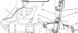
Scheme of operation of the hydraulic system of the T-25 tractor
Operating principle of T-25 hydraulics
The main pressure in the system is generated by an oil gear pump, which supplies oil to the distributor under high pressure and takes it back to the tank.
The dependent position of the distributor spool forces oil to flow up or down into the hydraulic cylinder cavity. The oil drains from the distributor back into the expansion tank.
Purpose and structure
The hydraulics of the T-25 tractor is a structure whose main task is to lower and raise equipment mounted on it to control trailing mechanisms, hydraulic devices, implements, etc. The structure of this system is represented by an oil tank and an oil pump, power cylinders, oil lines and a distributor – a special device that supplies and discharges oily liquid into and out of the tank.
It is customary to use diesel oil as a working lubricant. This raw material completely fills the tank, which is located at the back of the equipment. When oil enters the hydraulic lift from the distribution tank, it must be cleaned. Filters are installed for this purpose. When the filter compartments become clogged, oil fluid flows around the surface of the safety valve, which opens at that moment. The working fluid level is periodically checked with a special device - a dipstick. This instrument is marked with minimum and maximum level indications.
Operating principle
The working pressure in the hydraulic system of the equipment is generated through the stable operation of oil gear pumping equipment. The task of this element is to supply oil to the distributor and take it in the opposite direction. In this case, the oily liquid enters and exits the hydraulic cylinder, bypassing the spool. After the liquid enters the distributor, it is again drained into the expansion tank.
Possible breakdowns and ways to eliminate them
For stable operation of the hydraulics of the T-25 tractor, it is necessary to periodically carry out scheduled diagnostics to timely identify faults that can lead to serious problems in the future. The main failures of the system include:
- slow rise or its complete absence;
- the handles do not return back to the standard position in automatic mode.
The main signs that indicate not the first malfunction are:
- Shutdown of pumping equipment. To eliminate this, the engine is started, after which the lever moves towards the connecting body.
- There is no oil or a minimal amount.
- There are contaminants (dust, debris, sand) on the working surface of the bypass valve. To remove them, you need to remove the valve and clean its conical surface and edges. After which the parts are washed in diesel fuel, lubricated with oil and installed back.
- The distributor shank does not work or moves slowly. For its smooth operation, it is necessary to rinse and clean the valve thoroughly until it moves freely.
- The pump does not produce the required pressure. The sealing cuffs need to be replaced.
- The union nuts are in a loose position. You will need to tighten the parts until they stop, freeing them from the crosspieces if necessary.
The second breakdown can be caused by cold oil, low operating pressure, or clogged automatic device filter. If such problems occur, the pumping equipment should be replaced or comprehensively serviced, the oily liquid should be heated to the optimum temperature of 20°C and the filter device should be washed.
Hydraulics of the T-40 tractor
The hydraulic system of the T-40 tractor consists of two main components:
- power steering system,
- separate-aggregate hanging system.
The first system is responsible for reducing the force applied to the steering wheel, and the second allows you to control semi-mounted and mounted units that can perform specific functions. Repair prices for T-40 tractors are an order of magnitude lower than T-25 or T-16 due to the availability and prevalence of this model.
Technically, the T-40 hydraulic system is made of the following main components and assemblies:
- hydraulic tank with filter,
- gear pump,
- flow division valve,
- hydraulic distributor,
- remote and main hydraulic cylinders,
- power steering,
- pipelines and hoses,
- couplings,
- locking devices.
The operation of the hydraulic system is as follows:
- The gear pump forces the oil coming from the hydraulic tank to the flow sharing valve.
- 2 flows come out of the valve - to the power steering and to the aggregate system.
- in the aggregate system, the oil flow is received by a hydraulic distributor, which either drains the oil back into the hydraulic tank through the oil drain line, or directs the oil to the following components: the main hydraulic cylinder, mounted hydraulic drives connected to the tractor.
- The hydraulic drives are equipped with breakaway and locking couplings to prevent oil loss when the remote unit is unintentionally disconnected from the tractor or when additional remote units are routinely disconnected.
Pumps.
The hydraulic pump supplies fluid to the system components. The pressure in the system will develop in response to loads. Pumps have a power density of about ten times that of an electric motor. The pumps are designed to be driven by an electric motor or mechanical drive, which is connected through transmissions, belts, or a flexible flexible coupling to reduce severe vibration.
Common types of hydraulic pumps include applications: Gear Pump - A gear pump is cheap, durable, and simple. This is less efficient simply because this bias constant is suitable for pressures that are below 3000 psi. Vane Pump - Vane pumps are cheap, simple, and reliable. They are good for systems with low flow at low pressure outlet.
Hydraulics of the T-25 tractor
The hydraulic system of the T-25 tractor consists of a main hydraulic system and a rear linkage (a mechanism for hanging agricultural implements).
Let us list the main components of the tractor hydraulic system:
- oil tank,
- gear oil pump,
- hydraulic distributor,
- locking couplings,
- power cylinders (maybe several),
- connecting hoses and channels.
The operation of the hydraulic system of the T-25 tractor is as follows:
- From the tank, oil is pumped by a gear pump into the hydraulic distributor,
- From the hydraulic distributor, oil under pressure flows to the power hydraulic cylinder,
- excess oil flows back to the distributor through another oil line, from where it is drained through the filter into the hydraulic tank,
- If the filter is clogged, a safety valve is activated, allowing oil to be discharged into the tank bypassing the filter element.
Hoses and tubes.
Hydraulic hoses vary in pressure, temperature, and fluid compatibility. The rubber shell is surrounded by many layers of fabric wire and rubber. The outer shell of the hose is designed to resist abrasion. The bend radius of a hydraulic hose is designed very carefully, since failure of the hose can be dangerous, violation of the minimum bend radius of the hose can also lead to failure.
Hydraulic cylinder of the T-25 tractor.
Hydraulic tubes are strong and thick-walled and are used for high pressure systems, although some prefer hoses. The tubes are connected to each other by welding or using couplings and various fittings. Hydraulic tubes are preferred over hoses whenever possible as they are more durable and weigh much less. Hydraulic tubes usually have union nuts at the ends for connection to hydraulic equipment. They can also be welded or with floating couplings and seal fittings.
Pipes for hydraulic systems are usually coated with an anti-corrosion coating or painted, since the temperature and oil in which they operate, as well as moisture, do not reduce corrosion.
Hydraulics of the T-16 tractor
The hydraulic system of the T-16 self-propelled chassis (tractor) consists of the following main parts:
- oil tank equipped with a filter,
- oil pump,
- two remote hydraulic cylinders,
- connecting fittings.
The oil pump receives torque from an independent power take-off shaft. The main work is performed by the distributor, which is equipped with two spool valves (according to the number of controlled hydraulic cylinders), which can have 4 positions: “Lifting”, “Lowering”, “Floating” and “Neutral”.
Electric power steering of the T-25 tractor. Here is a classic representative of the T-25 tractor family. This tractor is T-25 with minor changes. Actually the changes are as follows; tie rods all cost a standard 700 watt generator. 50A. The power mode of the generator with the installed electric amplifier (EUR) is about 25A. When you turn on the electric lighting of the headlights and turn indicators, an additional 20A is added. A total of 45A. But if this happens when you turn on everything that can be turned on from the tractor’s electrical equipment, which in reality practically never happens. The standard generator is sufficient to power the electric power steering. What about the alternator belt, the service life of the belt with the electric booster installed has not been checked.
Additionally, electric power steering (EPS) has been added. The electric booster starts only when the engine is running, so as not to drain the battery. The change consists literally in installing instead of a classic steering column, installing a steering column with electric power steering from an opel combo car. The steering column switches and the ignition switch are also connected; the front axle itself is not jacked up anywhere. The steering wheel on the tractor is installed with an airbag, which is important when the tractor overturns.
The classic steering is inconvenient; it is difficult to turn the steering wheel in place. Let's move on to the real-time test. We start the tractor with the electric power steering (EPS) installed, the steering wheel turns in place (which is not recommended) without effort by turning one hand, which gives a pleasant pleasure and turns the tractor in a limited space. The paddle shifters are located under the new steering column in a convenient position. The advantages of such switches over toggle switches when driving in populated areas are simply unimaginable.
The electric power steering works smoothly when hitting any obstacle, the steering wheel does not knock you out of your hands. When you hit a slab, the steering wheel is released from your hands and the steering wheel slightly rocks in both directions. When driving into a furrow, nothing happens on the steering wheel, the tractor moves straight without any deviations. When driving along a furrow, the electronic unit and the electric amplifier itself were a little warm. This means that the rut is not scary for him. The number of turns on the steering wheel has not changed, which is approximately one and a half turns per side, i.e. as was the case with classic steering, the gear ratios did not change.
The electric amplifier is installed on a standard pipe, with a homemade boot installed on it. When installing the electric booster, nothing was cut or changed in the design of the tractor; everything was installed in its original place. The instrument panel has not been changed. The only thing that is there is electric power steering (EUR) with a mirror arrangement of the motor (right-hand drive cars) and the hydraulic distributor lever on the tractor (it is removed in the photo) is covered by a motor, you will only have to install this lever modified.
Let's summarize the operation of the electric amplifier.
The electric booster has the right to live; on tractors such as the T-25 it is quite a suitable option. There will never be any oil leaks if you suddenly have to disassemble something. You will have to unscrew a few wires, not several hydraulic hoses (when installing a hydraulic steering system) that then ooze oil. At the same time, the electric power steering (EPS) is 2-3 times cheaper than the hydraulic power steering system. Also, the electric booster does not require oil, there is no need to monitor the oil level, there is no need for an oil tank or a hydraulic pump. There is no need to change steering rods, which reduces reliability. In general, all the advantages of electric power steering for the T-25 tractor.
Electric power steering of the T-25 tractor
Tractor T-25
Related posts:
- 10 reasons to buy a T-25 tractor
- Tractor T30a-80 “Vladimerets”
- Which car oil is better
- How to start a diesel tractor engine in cold weather. Problems and...
- Do you need a license for a mini tractor?
- Mini tractor made from Agro walk-behind tractor
