What is a fuel injection pump bypass valve
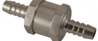
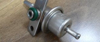
The injection pump bypass valve (reducing valve) is a high-pressure fuel pump assembly of diesel engine power supply systems, an adjustable valve (hydraulic throttle) for draining excess fuel and maintaining the required fuel pressure in the pump.
The bypass valve performs several functions:
- Draining excess fuel from the pump;
- Removing air trapped in the fuel system;
- Maintaining constant fuel pressure inside the pump (in the channels of the pump sections of multi-section high-pressure fuel pumps and in the housing of the distribution high-pressure fuel pumps).
A pressure reducing valve is an automatic hydraulic throttle - a device that creates resistance to fluid flow and has the ability to change the intensity of this flow depending on the hydraulic pressure. In a certain pressure range, the bypass valve is closed or creates high resistance to fluid flow; when a certain threshold pressure is exceeded, the valve opens and dumps excess fuel from the pump, preventing further pressure build-up.
The bypass valve is part of the low pressure section of the injection pump; it operates automatically and only needs to be adjusted to set the response threshold.
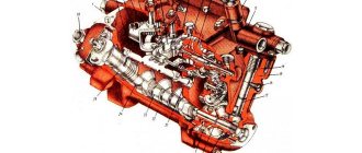
High pressure fuel pump (HFP) KamAZ
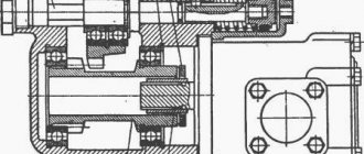
A high-pressure fuel pump (HPF) of a plunger type is designed to supply strictly metered portions of fuel under high pressure (depending on the engine mode) to the injectors at certain times.
There are eight sections in the pump housing 1, each of which consists of a housing 17, a plunger sleeve 16, a plunger 11, a rotary sleeve 8, a discharge valve 19, pressed through a sealing gasket 18 to the plunger sleeve by a fitting 20.
Rice. Diagram of the KamAZ high pressure fuel pump: 1 - housing; 2 — pusher roller; 3 and 31 - roller axis; 4 — roller bushing; 5 — pusher heel; 6 - cracker; 7 — pusher spring plate; 8 — rotary sleeve; 9 — pusher spring; 10, 34, 43, 45, 51 and 55 - washers; 11 - plunger; 12 and 13 - sealing rings; 14—locating pin; 15 — right rail; 16 — plunger bushing; 17 — section body; 18 — discharge valve gasket; 19 — discharge valve; 20 - fitting; 21 — section housing flange; 22 — fuel priming pump; 23 — spring plug, 24, 27 and 48 — gaskets; 25 — rod bushing; 26 — low pressure pump housing; 28 — pusher spring; 29 — pusher; 30 - locking screw; 32 — pusher roller; 33 and 52—nuts; 35 — low pressure pump drive eccentric; 36 and 50 - keys; 37 — flange of the regulator drive gear; 38 — holder of the regulator drive gear; 39 — drive gear of the regulator; 40 - thrust bushing; 41 and 49 — bearing caps; 42 — bearing; 44 - cam shaft; 46 - sealing ring; 47 — cuff with a spring; 53 — fuel injection advance clutch; 54 — rack plug; 56 - bypass valve; 57 — rack bushing
The plunger performs a reciprocating movement under the action of the cam of the shaft 44 and the spring 9. The crayon 6 prevents the pusher from turning in the body.
The cam shaft rotates in roller bearings 42 installed in covers attached to the pump housing. Axial movement of the cam shaft is eliminated by selecting adjusting shims 48.
To increase the fuel supply, turn the plunger using a rotating sleeve, which is connected to the rack 15 of the pump through the axis of the driver. The rack moves in guide bushings 57 along a channel that is closed by plug 54. On the opposite side of the pump there is an adjusting screw for fuel supply by the pump. This screw is usually capped and sealed.
Fuel is supplied to the pump through a special fitting, to which a low pressure pipe is bolted. Further, through the channels in the housing it flows to the discharge sections.
The pump is lubricated by circulation, under pressure from the general engine lubrication system.
ustroistvo-avtomobilya.ru
Types, design and principle of operation of the injection pump bypass valve
First of all, it should be noted that today there are several types of valves that provide fuel bypass to the injection pump:
- Bypass (reducing) valve in multi-section pumps;
- Bypass (reducing) valve for regulating pressure inside the housing (at the inlet to the pump section of the fuel priming pump) in a distribution-type injection pump;
- Bypass throttling valve in distribution type pumps.
Each of the valves has its own design features and occupies a specific place in the high-pressure fuel pump.
Bypass valve in multi-section fuel injection pumps. This valve is installed in the front wall of the pump housing; it is connected to the fuel supply channels from the fuel priming pump to the discharge sections. Structurally, the valve is very simple: its basis is a body, inside of which there is a spring-loaded shut-off element in the form of a ball or disk. The housing can be of two types:
- Bolt. The valve is made in the form of a bolt, inside of which there is a shut-off element, and two or more holes are made on the walls to drain fuel into the return line. The bolt is screwed into the pump body; it holds the connecting nipple, to which the return line is connected;
- Union. The valve is made in the form of a fitting, inside of which there is a shut-off element. The fitting is screwed into the pump housing, and the return line is connected to the external thread.
This type of bypass valve works as follows. At low pressure in the supply line, the valve is closed due to spring force - fuel is supplied to the discharge sections. When the engine operating mode changes, the operation of the injection pump and the fuel priming pump also changes; at some point, the fuel pressure in the supply line increases, which can complicate the operation of the injection sections. When the threshold pressure is exceeded (which lies at the level of 58-80 kPa), the spring force is overcome and the valve opens - excess fuel is discharged into the tank through the return line. When the pressure drops, the valve closes again.
It should be noted that in multi-section pumps, the pressure reducing valve is mainly responsible for removing excess fuel, and air is removed from the system by a nozzle valve installed on the fine fuel filter.
Bypass valve of distribution injection pumps. This valve performs the same functions as the bypass valve of multi-section pumps. It is installed immediately after the fuel priming pump and discharges excess fuel when the pressure rises. The valve can be made in the form of a bolt or fitting, or it can be built directly into the pump housing.
Throttling valve for bypass of distribution injection pumps. This unit combines two parts - a fuel drain nozzle and the bypass valve itself. Distribution-type pumps have a drain jet - a small-diameter hole through which fuel is constantly drained into the return line. The jet circulates fuel through the pump, due to which the parts of the unit are cooled and air is removed from it. In some pumps, there is no nozzle as such; it is combined with a bypass throttling valve, which at low pressure always allows a certain amount of fuel to pass through, and when the pressure rises, it opens and dumps excess fuel into the return line.
How to Check the Injection Pump Check Valve – Driver Tips and Reviews
Troubleshooting: fuel system check valve
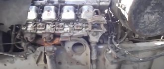
Fuel systems of automobile engines are a rather complex device, which is contraindicated to approach without knowledge of certain basic concepts. Knowledge of hardware and minimal experience are the main components that will help overcome any malfunction. You won't even be able to disassemble the wheel by force. Training is needed. And the fuel system is a complex set of devices that seem elementary only at first glance.
The photo shows a car fuel system, the repair of which should only be done by a specialist
Even the usual power system of an old VAZ 2101 can perform such a trick that modern technologically advanced engines have never dreamed of, not to mention diesel engines of recent years, where there are two electronic sensors for every centimeter of the fuel line. Such a trivial thing as a check valve can cause confusion even in an experienced mechanic, but if the average car enthusiast starts talking about a check valve, then it’s worth looking into it in more detail.
Fuel system check valve
Any check valve in any hydraulic system serves to ensure that fluid flows along the line in only one direction. This may be necessary in many cases, but when applied to a fuel system, a check valve prevents unused fuel from draining from the fuel line into the tank. For various reasons, but that's the gist. This applies to both gasoline engines with carburetors, injection engines, and diesel engine power systems.
Video about the operation of a check valve
Structurally, most often the check valve is designed extremely simply - it is a ball valve with a precisely calibrated seat made of soft metal. The valve allows fuel to pass unhindered in one direction, but at the same time fuel cannot flow back into the tank, closing the valve with its own pressure. A simple device, nothing complicated, but sometimes its malfunction or simple absence leads to serious problems. People often confuse a pressure relief valve and a check valve, but these are completely different things. In diesel and injection engines, where pressure is required for the operation of the power system, the pressure reducing valve is responsible for stable pressure, however, it works in tandem with a check valve. It’s logical to solve all problems as they arise, so that’s what we’ll do.
Where is the check valve located?
Man tga. Repair. Injection pump check valve.
Adjusting the pressure of the booster pump on LT Bosch VE.
Check valve for injection pump BOSCH VE
We're starting a review.
You need to know the enemy by sight, so let's start by looking for a check valve in car power systems. The valve can be installed in the fuel pump housing of injection engines, on the fuel rail, or simply in the fuel line between the gas tank and the fuel injectors. On diesel engines, it is installed between the low-pressure hand pump and the injection pump so that the pressure at the inlet to the high-pressure pump is always stable. This system is installed on all KAMAZ 740, Tatra, MAN and Renault Magnum engines. In diesel engines with a fuel preheating system, a check valve is necessarily installed in front of the heating system, as in Magirus trucks, the same KAMAZ of the Arctic version, and many others.
The check valve for injection engines may be located on the fuel frame
In domestically produced passenger cars with injectors, the 16-valve VAZ 2110, 2114, the check valve is installed in the fuel pump and on the fuel rail, similar to the diesel system. In old carburetor cars, VAZ 2108, 2109, classic rear-wheel drive models, the role of a check valve is played by the fuel pump itself, which is installed on the cylinder block and does not allow fuel to flow back into the tank, thanks to the sealed outlet valve of the fuel pump. When the valve loses its tightness, the gasoline goes completely into the tank, and the engine can only be started with manual pumping.
Prudent owners independently installed return valves to make starting the engine easier. On old models of the Opel Cadet, Mazda 323, when starting was difficult, it was enough to buy and install a check valve into the power system closer to the carburetor or mono-injector, and the fuel stopped flowing through the working line into the tank, and the start became normal even at sub-zero temperatures.
What to expect from a non-working check valve
Nothing good. At the very least it is a difficult start. Airing of the diesel power system is a rather problematic breakdown on the road. Injection power systems also do not like air in the system. Troubles begin when we turn off the engine, and the fuel, which must wait for the next start (working pressure must be maintained in the system), goes into the tank along the working line, and air takes its place. Now, in order to start the engine, it is necessary to normalize the pressure in the system and supply fuel to the injectors. To do this, you need to turn the engine with the starter for 40-50 seconds, so starting with half a turn is out of the question.
Strange situations also arise when the check valve is confused with the pressure regulator, which is installed on the fuel rail in most injection engines - 2110, 2114, Kia Sportage 3.
Airing the diesel power system is an extremely complex breakdown on the road
Its job is to equalize the pressure in the fuel rail section, otherwise the injector simply will not receive fuel at the required pressure and will not be able to supply it to the combustion chamber. At the moment when we turn off the ignition, the regulator stops supplying fuel to the injectors, the locking mechanism is activated, thus cutting off part of the fuel line from the fuel pump with a check valve to the fuel rail. And now only the check valve is responsible for the presence of fuel in the system. And it’s easy to check who is to blame in this situation. If the pressure in the fuel rail is normal, and in most cars it should be within 2-3 atm, then the check valve is to blame.
As you can see, one tiny valve can do such things. This once again confirms that there are no small things in the car’s design and there cannot be, and every breakdown is eliminated first with the head, and only then with the hands.
5net.ru
Correct selection and replacement of the injection pump bypass valve
Reducing valves have an extremely simple design, but they are constantly subjected to high loads and quite often fail. Valve malfunction is manifested by deterioration of engine performance - it loses throttle response and in some modes there is a noticeable deterioration in its performance. In these cases, it is necessary to dismantle and check the valve, and, if it is faulty, replace it.
To replace, it is necessary to select a bypass valve of the same type and model that is installed on the injection pump by the manufacturer - only in this case there is a guarantee that the valve has the necessary characteristics and will ensure normal operation of the pump. Many valves allow adjustment of the pressure at which fuel is bypassed - this adjustment must be made in strict accordance with the instructions for maintenance and repair of the car/tractor. As a rule, adjustment comes down to changing the number of washers placed under the valve head, although there are exceptions - it all depends on the specific type of device.
With the correct selection, replacement and adjustment of the pressure reducing valve, the fuel pump will operate effectively in all modes, ensuring normal operating characteristics of the power unit.
The KamAZ injection pump is a mechanism designed to supply fuel fluid to the cylindrical mechanisms of the engine.
Check valve for KAMAZ pump
Man tga. Repair. Injection pump check valve.
How to Test a Fuel Check Valve
KAMAZ EURO-2 stalls while driving
Check valve for injection pump BOSCH VE
Kamaz troit stalls
CHECK VALVE
Body lift limit valve. Principle of operation. Repair. Service.
Pump KAMAZ China 1
Installing a check valve on a centrifugal fuel pump
Fuel check valve. Parcel from China No. 9
Also see:
- KAMAZ starter torque
- What happens if you turn off the return line on a KAMAZ
- KAMAZ manipulator boom 9 tons
- KAMAZ visor mounting bracket
- Shell Rimula for KAMAZ
- Hand brake valve KAMAZ 65115
- Replacing the KAMAZ abs sensor
- Gearbox malfunctions on KAMAZ
- Internal dimensions of KAMAZ 5320
- KAMAZ 4310 engine video
- KAMAZ trucks with a barrel
- Distribution valve of the KAMAZ brake system
- How to make KAMAZ more powerful
- How to engage first gear on a KAMAZ
- What is a KAMAZ contactor?
Home » Popular » Check valve for KAMAZ pump
kamaz136.ru
Design and principle of operation
The fuel injection pump device includes such mechanisms as:
- pump compartment housing;
- high pressure fuel pump bearing cover housing;
- inflation hose;
- plunger pair and plunger pusher;
- spring elements;
- mode selection regulator and coarse and fine filters;
- fitting for the fuel drain and injection system;
- fuel injection regulator;
- pressure reducing valve;
- an electromagnetic valve, which is necessary to shut off the fuel supply;
- rack, nozzle and coupling half.
The operating principle of the injection pump is as follows:
- Movement is set from the crankshaft mechanism using a mechanical transmission.
- The rotation of the cam shaft begins. This rotation provokes displacement of the pusher elements.
- The pushers begin to compress special springs.
- The springs cause the plunger to start working and lift it.
- The plunger closes the intake valve and displaces fuel fluid.
- The fuel begins to be sprayed using nozzles.
- The plunger lowers and opens the intake mechanism.
Where is the check valve located?
The check valve is located on the fuel rail between the fuel tank and the injectors.
Pressure relief valve - diagram and device
Figure No. 2 shows a brief diagram of the operation and design of the mechanical emergency fuel dump valve. These valves are mechanical (direct-acting), less common are electro-mechanical valves (indirect-acting). Mechanical safety valves, such as our example, include:
- Housing with external thread for installation in the fuel rail.
- Drain channel for fuel return.
- Plunger with a conical part.
- Return spring.
Source
Malfunctions and repairs
You can repair KamAZ fuel injection pump yourself if you have the necessary tools and equipment.
Main fuel injection pump malfunctions and reasons for their occurrence:
- Water in the fuel mechanism. This breakdown may indicate a malfunction of the fuel filter element, diluted fuel, or a leak in the fuel drives.
- Reduced and uneven supply of working fluid. In this case, it is recommended to check the plunger for damage, and also inspect the discharge valves and rack clamps. The capacity of the injectors should be checked.
- The diesel fuel is running out. The cause of this breakdown may be a leak in the fuel drive. The damaged element should be replaced.
- The drive is tearing. It is recommended to inspect the crankshaft, as well as the main components of the power unit for damage and foreign bodies.
- Delay of the working fluid injection system. Such a malfunction can be caused by damage to the plane of the adjusting bolt of the pusher element, the roller axis and failures in the rotation speed of the cam shaft.
Price and reviews
Injection pump purchase and rental price:
- purchase - from 17,500 rubles;
- This vehicle part cannot be rented.
Vladimir, 39 years old, Magnitogorsk: “I’ve been working at KamAZ-53215 for the second year now. Recently I started having problems with the high pressure fuel pump. A Euro-3 version was installed, and the fuel injection pump had to be replaced.”
Vitaly, 41 years old, Vladivostok: After 4 years of operation of the KamAZ, fuel fluid began to leak. The cause of the breakdown was a broken seal of the fuel drive and pump.
The repair was done quickly, because... all spare parts are easy to find.
Mikhail, 53 years old, Krasnodar: “The truck has an injection pump installed according to Euro-4 standards. The problems started after 2 years of operation. All failures were associated with uneven supply of working fluid. I entrusted the repair to the specialists at the service center.”
Symptoms of malfunction of fuel injection pump KAMAZ 740, fuel injection pump KAMAZ 4310
Malfunctions of fuel pumps and regulators manifest themselves in a violation of adjustment due to wear of parts, which results in the occurrence of extraneous noise, overheating and fuel leakage.
The main reason for the malfunction of the fuel pump is wear of its parts, weakening of the tightness in the fits, increased gaps in the moving joints, violation of the location of the parts, and deposits on the surface of the parts in the form of dirt and carbon deposits.
The consequence of pump malfunctions can be a decrease in the supply of fuel in the required quantity and uneven supply. Failure to properly supply fuel is usually caused by wear of plunger pairs, pump discharge valves, plunger drivers, rack clamps, rack teeth and bushing gears, and clogging of injectors. Such malfunctions lead to a decrease in engine power and efficiency.
Uneven supply of fuel to the engine cylinders will lead not only to unstable operation at low speeds, but also to interruptions in the operation of individual cylinders, which will be accompanied by vibration of the engine block.
Fuel injection pump malfunctions include uneven start of injection and delay in injection timing of a multi-section pump, which occurs due to wear of the pusher adjusting bolt, roller axis, pusher and roller housing, ball bearings, as well as wear of the cam shaft.
Wear of plunger pairs and injection valves significantly affects the change in the fuel injection advance angle.
- The KAMAZ engine does not start or starts poorly;
- Uneven operation of the KAMAZ engine;
- During operation, noises and knocking noises from the KAMAZ engine occur.
Fuel system check valve: purpose, location, problems
The fuel supply system ensures fuel purification and its uniform distribution throughout the engine cylinders in dosed portions and at strictly defined times.
The engines use a split-type fuel supply system, consisting of a type 337 fuel injection pump with a speed controller, a fuel priming pump, injectors, coarse and fine filters, a pre-start pump, high and low pressure fuel pipes, a solenoid valve and EFU flare spark plugs.
The fuel supply system diagram is shown in Figure 1.
A fuel coarse filter and a fuel pre-priming pump must be installed in the fuel supply system of the facility where the engine is used.
Fuel from the tank is supplied through the coarse filter and the pre-start pump 18 by the fuel priming pump into the fine filter 16.
From the racing filter through the low-pressure fuel pipe 14, the fuel enters the injection pump 21, which, in accordance with the operating order of the cylinders, distributes the fuel through the high-pressure pipes 1-8 to the injectors 10. The injectors inject fuel into the combustion chambers.
Excess fuel, and along with it the air that has entered the system, is discharged into the fuel tank through the injection pump bypass valve 24 through tube 12 and the fine filter nozzle valve 23.
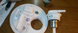
The nozzle (see Fig. 2) is a closed type, with a five-nozzle sprayer and hydraulic control for lifting the needle mod. 273-31 for engine mod. 740.11-240. Maud. 273-21 with sprayer JSC "YAZDA" or mod. 273-51 with sprayer for engines mod. 740.13-260 and 740.14-300.
All parts of the nozzle are assembled in body 6. A spacer 3 and nozzle body 1, inside of which there is a needle 12, are attached to the lower end of the nozzle body with a nut 2.
The body and the atomizer needle form a precision pair. The sprayer has five spray holes.
Spacer 3 and body 1 are fixed relative to body 6 by pins 4.
Spring 11 rests at one end against rod 5, which transmits force to the spray needle, and at the other end against a set of adjusting washers 9, 10.
Fuel is supplied to the injector under high pressure through fitting 8 with a slot filter 13 built into it, then through the channels of housing 6, spacer 3 and sprayer body 1 into the cavity between the sprayer body and needle 12 and, lifting it, is injected into the cylinder.
The fuel that has leaked through the gap between the needle and the nozzle body is discharged through the channels in the nozzle body and drained into the tank through drainage pipes 9 and 11 (see Fig. Engine fuel supply system).
The main reasons why the KAMAZ engine does not start:
- There is no fuel in the fuel tank;
- Presence of air in the fuel system;
- Clogged or contaminated fuel lines of the KAMAZ power supply system;
- The fuel has thickened due to low temperatures;
- Malfunctions of the high pressure fuel pump (injection pump malfunctions)
- Clogged fuel filters.
To determine the malfunction of the power system, you should follow the chain from less expensive and costly faults to more costly ones, taking into account the flow chart for repairing the power system.
Common Rail Fuel Rail Pressure Relief Valve
In this article we will look at the device, design, installation location and operating principle of the pressure relief valve for the fuel system of Common Rail diesel engines. This valve has many names and is often called not entirely correctly on the Internet. Let's look at the most common names and decide what is true and what is not. In Bosch terminology it is simply called: pressure regulator valve . Based on its design and purpose, the correct names will also be: fuel pressure relief or emergency relief valve, safety valve and fuel pressure limiting valve in the fuel rail. And names such as fuel rail pressure reducing valve or check valve will not be entirely correct. Reducing valves provide constant (reduced) outlet pressure and this valve cannot possibly meet this characteristic. You can read more about pressure reducing valves on Wikipedia. According to the principle of operation, this valve is a safety valve. According to the classification of the EAEU foreign economic activity product nomenclature, this valve belongs to the category “Safety or unloading valves”, foreign economic activity code 8481401000 .
Valve purpose
The common rail fuel rail pressure relief valve functions as a safety valve. In cases where the set pressure is exceeded, the valve limits the pressure in the Common Rail accumulator by opening the drain channel. The maximum fuel pressure in the rail, briefly allowed by this valve, most often varies in the range of 1500 - 2300 bar and depends on the manufacturer and the specific model of the fuel system.
Valve installation location
The pressure relief valve is installed (screwed) directly into the fuel rail/rail. In Figure 1, this valve is indicated on the right under number 5. A pressure relief valve is installed on the right side under number 5, and an electric fuel pressure sensor is installed on the left side under number 8. The pressure relief valve is always connected to the fuel return line.
Valve operating principle
The valve operation algorithm is quite simple. In normal mode and operating pressure in the fuel rail (accumulator), the valve is in the closed position - the built-in spring presses and holds the plunger in the seat, and fuel does not drain from the battery into the return line. As soon as the pressure in the fuel rail exceeds the set value, the plunger is pressed out under the force of fuel pressure, overcoming the resistance of the valve return spring, and fuel under pressure through the resulting gap enters the internal cavity of the plunger and then into the return line - as a result, the fuel goes back into the tank . Next, the fuel pressure in the fuel rail is normalized and the valve closes.
The KAMAZ 740 engine does not develop full power
- Replace the air filter;
- Adjust the fuel supply angle;
- Clean the injectors, adjust the injectors;
- Repair the injection pump;
- Check the operation of the KAMAZ injection pump.
Uneven operation of the KAMAZ 740, KAMAZ 4310 can be caused by loss of functionality of individual injectors, a malfunction of the high-pressure fuel pump or its regulator. Damaged injectors must be replaced, and the injection pump, as a more expensive part, is checked on a fuel stand and repaired if necessary.
Check valve on the Bosch KAMAZ pump
Check valve for injection pump BOSCH VE
KAMAZ EURO-2 stalls while driving
How to Test a Fuel Check Valve
Injection pump Bosch Kamaz Euro 2
Man tga. Repair. Injection pump check valve.
Kamaz troit stalls
Checking a faulty and serviceable Bosch VP30 injection pump valve on the engine and on the stand
REPAIR OF DIESEL ENGINE FUEL PICKUP PUMP (TPN, TNND)
modification of the Mitsubishi Pajero injection pump return valve (Mitsubishi Pajero), with a 4m40 engine for Kamaz
Fuel check valve
Also see:
- Purpose of the KAMAZ 740 engine oil pump
- Box KAMAZ 141
- KAMAZ 5320 agricultural technical specifications
- Video of KAMAZ assembly at the factory
- All KAMAZ 5460 models
- The better KAMAZ MAZ
- Steel for KAMAZ cabs
- KAMAZ pike new
- Gas system for KAMAZ
- KAMAZ 5 tonic model
- KAMAZ 5440 dump truck
- Tech KAMAZ 4310
- KAMAZ 6520 front spring size
- Fuel line diagram for KAMAZ
- Dump trailer KAMAZ 65115
Home » Selections » Check valve on the Bosch KAMAZ pump
kamaz-parts.ru