Currently, many owners of home workshops equip them with modern tools and equipment, which, being highly efficient and easy to use, significantly facilitates work and increases its productivity. However, at the same time, quite technically simple devices that can be made with your own hands in a home workshop are still in demand. One of them is a reduction gearbox.
What is a reduction gearbox?
It is a special type of mechanism that serves as a transmission link between devices in which the active parts perform rotational motion. It is often used to transmit and convert torque from the unit that produces it to the device that uses the mechanical energy supplied to it. Unlike other types, a reduction gearbox provides a reduction in the number of revolutions and an increase in torque.
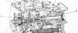
A reduction gearbox consists of a housing, gears, transmission chains, a worm mechanism, and shafts, with the help of which torque is transmitted and converted.
Toothed gears are located on the shafts in a rigid coupling, and worm gears are attached. They ensure the transfer of motion to each other, during which its transformation is carried out.
There are different types of reduction gearboxes:
In addition, they are:
Preliminary preparation
Before you begin creating this device, you must have general knowledge of mechanics, be able to use repair tools and equipment, and know the operating principle and structure of this unit.
In addition, you need to initially determine:
- the type of future gearbox and its version;
- the gear ratio that will need to be converted and determined at the output;
- indicators of dynamic loads that will affect the working parts of the device;
- weight and dimensions of the future device;
- installation angle;
- temperature limits that will occur in the device during its operation;
- switching cycle – full or variable;
- intensity of operation.
Wheel reducer maintenance
To increase the reliability of the unit and extend the period of its safe operation, it is necessary to carry out its technical inspection and appropriate maintenance at certain intervals, using special monitoring and measuring equipment. Before starting repair work, you must first disconnect the gearbox from the clutch housing, under which, however, like under the front axle, movable stands are installed. A fixed type stand is placed under the gearbox. Next, you should turn off the hydraulic system and disconnect the tractor frame, roll it out and disconnect the half-frame from the clutch housing.
After disassembly is completed, you can proceed to diagnosing the unit, first of all paying attention to the following points:
- Indicators of oil level in the hydraulic tank;
- Is the engine operating at full power?
- What condition is the chassis in?
- Is there an oil leak?
- Is there pressure in the drain line of the hydraulic motor and at its inlet;
- What is the condition of the fastening joints?
- Are the roller bearings in good condition?
- Does the gear clutch system on the upper and lower bevel pairs need to be replaced?
If, during the inspection of the wheel gearbox, a significant decrease in the oil level in the upper bevel pair is detected, then this is a sure sign that there is a leak in the system. It is imperative to identify the causes of its occurrence and eliminate the malfunction as quickly as possible. It is quite possible that this may even require partial disassembly of this unit, although, in fact, this is the only way to fix the problem.
More details about the components
The assembly process is not as complicated as the selection or production of spare parts necessary for such a gearbox.
- Device body. In industry it is produced by casting. The necessary holes are made using high-precision equipment, since it is necessary to achieve the mutually correct arrangement of the shafts and the alignment of the stars. When producing it, it is necessary to make the top cover removable. This will facilitate and simplify the process of servicing it during operation;
- Shafts and axles of the gearbox. They support gears and are used if they need to be equipped with this device. Installation is carried out by pressing onto splines or keys. For their manufacture, it is better to use durable steel measuring from 10 to 45 mm, which is easy to machine;
- Bearings. They are used as supports for shafts and resist loads and provide the possibility of rotational movement. Its reliability, durability and performance depend on the correct selection of these gearbox elements. If you are installing spur gears, then it will be sufficient to install conventional single or double row ball bearings. If a helical bearing or worm gear will be installed, then a roller or angular thrust ball bearing will be the best option. It is better to buy new ones than to use them from disassembly;
- Gears. They provide a change in the rotation speed of the shafts and, naturally, a reduction in the gear ratio. For their production, special metal-cutting equipment is used, which home workshops are not equipped with. The dimensions and characteristics of other parts included in this unit, as well as the distance between the axles and shafts, depend on the size of the gears. When installing, it is important to correctly set the gap between them. I-20 oil is perfect for lubricating gears. It is filled to the level of the bottom of the gears. Other parts of the device are lubricated by spraying lubricant onto them. You can take it from disassembly or buy new ones;
- Oil seals. They prevent oil from leaking out of the device body. They are installed at the exit points of the shafts on bearings under the covers. Are bought;
- Safety coupling. It is designed to prevent destruction of the device when excessive loads occur. Buyable;
- Bearing caps. They can be different - deaf and through. Designed to facilitate maintenance and installation of bearings. You can grind them yourself or find them at a disassembly site.
Reasons for unit failure
The main reasons for premature wear or failure are the use of low-quality (or incorrectly selected) oil or its untimely replacement, excessive loads of special equipment, leading to a weakening of the bottom connection of the coupling flanges and the input shaft. At an air temperature of + 25 degrees, the lubricant temperature should not exceed + 60 degrees, cylindrical wheels should be immersed in oil to the height of the teeth, conical wheels - the entire length of the teeth.
The oil is considered used when the permissible acidity level is exceeded, the viscosity changes by more than 25%, the water content exceeds 2%, and the presence of mechanical particle impurities exceeds 0.5%.
Rolling bearings, as an important component of the on-board unit, fail when low-quality lubrication is used, and gears fail when the contacts attached to the machine platform are loosened.
Symptoms of a problem
The main sign indicating a malfunction of the mechanism is extraneous noise, vibration or increased sound resonance during operation of the excavator. The second point indicating a problem in the operation of the system is the appearance of metal shavings on the cover of the device housing, oil seeping through the seals, and knocking in the gearbox. Loss of smoothness when changing speed and when turning is an indirect sign of a malfunction. If one or more warning factors are detected, it is necessary to carry out a diagnosis, after which the nature of the problem will be accurately determined and appropriate measures taken.
Repair method
In order to accurately determine the specifics of the malfunction, the unit must be dismantled, disassembled, and cleaned of grease. Next, the functionality of each part is checked, defective gears and shafts are replaced, after which the mechanism is assembled, debugged, and tested under different operating modes and loads.
Preventive inspection and scheduled preventive maintenance are the only reliable measures to ensure the normal functioning of special equipment (mini excavators, loaders, cranes). A professional approach to machine maintenance will significantly reduce operating costs, avoid equipment downtime and forced expensive repairs.
Final drive failure is one of the most common problems faced by operators of excavators, tractors and other types of heavy equipment. The specialists of our company are well aware of the design features of machines of different models and brands. Over the years of work, we have identified and systematized breakdowns of various types, which allows us to accurately determine the type of fault even by external signs. It is important to immediately contact specialists after the first signs of problems appear, since broken teeth of one gear quickly destroy all links of the transmission chain.
We use the latest diagnostic and repair equipment, have a site for post-repair testing, and have our own warehouse with original spare parts. We will repair or replace a gearbox with a hydraulic motor, select oil and lubricants, gears, shafts for different models of special equipment. Call 8 to coordinate a time for service station diagnostics, or leave a request on the website. The manager will contact you within a few minutes.
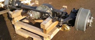
Final drive device
The design of the final drive is so simple that you can assemble it yourself. The basis of the mechanism is a gear that fits onto the splines of a standard drive. The second, driven gear rotates the wheel. To ensure that the direction of rotation does not change, intermediate (parasitic) gears are installed.
Typically the driven gear has more teeth than the drive gear. This allows you to increase the gear ratio and, if desired, equip the car with larger diameter tires.
The same principle applies to heavy tractor gearboxes such as T 170 or truck gearboxes, which are equipped with KamAZ or MAZ commercial vehicles. The only difference is that for tracked tractors and other equipment, the torque is transmitted not to the wheel hub, but to the track sprocket.
If necessary, repairs to the final drive can be done with your own hands. In most cases, to eliminate noise and vibration, it is enough to replace auxiliary elements: oil seals, floating seals, bearings, etc.
Peculiarities
Technical specifications
- Torque. Simply put, this is the force with which a body fixed on a certain axis is capable of rotating. A synonym for this parameter that is not entirely correct from a mechanical point of view is the term “torque.” Torque in cars ultimately determines the speed of rotation of the wheels.
- Angular velocity. This is the speed with which a certain material point rotates around a certain center. In relation to automotive technology, the value determines the power loss due to the movement of the transmitting device itself. The higher the angular speed, the lower the intensity of wheel rotation.
- The magnitude of the gear ratio. This parameter represents the relationship between the angular velocities or torques of the individual shafts that make up the machine’s transmission system. For running gearboxes this characteristic is the main one.
Since the point of a travel gearbox is to provide maximum useful work, in general this element increases torque and reduces angular speed. However, in some and quite rare cases, the system provides the opposite result. Such devices are called reverse gearboxes or, less commonly, multipliers. They reduce torque and increase angular velocity. Such devices are not used in transmissions of excavators and other special equipment.
Principle of operation
There are electrical and mechanical options. The second type of travel gearbox is most often installed in automobile transport. This design consists of two or three gears of different sizes, of which the smaller one is the driver and the larger one is the driven one. As they rotate, they touch teeth and transfer energy to the wheels.
Configuration
Our catalog contains about 50 models of Komatsu final drives for excavators and other special equipment:
- Complete final drives. They are a complete mechanism with all the structural parts necessary for normal functioning. All that remains is to insert them into an excavator or other special equipment, and you can work on it.
- Gearboxes are assembled without separate parts. The only difference is that the kit does not include a hydraulic motor. This type of motor simplifies the operation of the entire structure and makes it more efficient, but even without it the system functions properly. The hydraulic motor can be purchased in addition.
- Specialized gearboxes. To equip some types of special equipment, mechanisms of a special design may be required. There are also turntables (simple and assembled), slewing bearings and Komatsu final drives.
- Spare parts for gearboxes. To replace used Komatsu brand parts, we have shafts, gears, washers, carriers, pistons - more than 400 products in total.
We supply most samples of Komatsu final drives to order. The most popular samples are always in stock. These are eight models, one of which is equipped with a hydraulic motor.
Design
- Cylindrical. They compare favorably with others by their high level of efficiency and significantly lower energy consumption. Devices of this type can withstand heavy loads for a long time, hardly heat up during operation and do not have a self-braking effect.
- Planetary. Another name is differential. Among the advantages are compact dimensions, reduced noise level during operation, and high gear ratio.
- Worm-shaped. In designs of this type, two gears, usual for classical analogues, are replaced by a screw (worm) and a gear. These parts form a worm gear, the advantages of which are compact size, smooth running and high efficiency. The only downside is self-braking.
- Conical. The shafts are angled so that a cone is formed. This feature allows you to transfer force directly from the engine to the working element. However, due to the peculiar geometric configuration, the efficiency is lower than that of other devices.
- Combined. They are a combination of several options that combine two or more pure types of transmission. The most popular types are worm-cylindrical and conical-cylindrical elements. Combined systems have two main advantages: true overload protection and affordable cost.