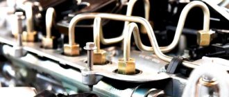
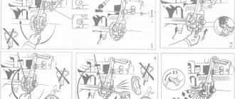
The Kamaz has difficulty starting, especially when it has been left overnight or some time has passed. When you start the engine, it starts to spin up and takes a long time to catch. This means there is an air leak somewhere, in the low pressure fuel system. The main reason for this phenomenon is that fuel flows back through the hoses into the tank. Why is this happening? Yes, because they do not hold the valves on the injection pump pump and fine fuel filters. Debris or hair can get into the valves and the valve will not hold pressure. There may also be air leaks at the connections of hoses and pipes where there are copper washers.
KAMAZ 740
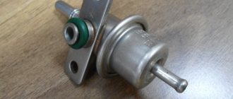
Common Rail Fuel Rail Pressure Relief Valve
In this article we will look at the device, design, installation location and operating principle of the pressure relief valve for the fuel system of Common Rail diesel engines. This valve has many names and is often called not entirely correctly on the Internet. Let's look at the most common names and decide what is true and what is not. In Bosch terminology it is simply called: pressure regulator valve . Based on its design and purpose, the correct names will also be: fuel pressure relief or emergency relief valve, safety valve and fuel pressure limiting valve in the fuel rail. And names such as fuel rail pressure reducing valve or check valve will not be entirely correct. Reducing valves provide constant (reduced) outlet pressure and this valve cannot possibly meet this characteristic. You can read more about pressure reducing valves on Wikipedia. According to the principle of operation, this valve is a safety valve. According to the classification of the EAEU foreign economic activity product nomenclature, this valve belongs to the category “Safety or unloading valves”, foreign economic activity code 8481401000 .
Valve purpose
The common rail fuel rail pressure relief valve functions as a safety valve. In cases where the set pressure is exceeded, the valve limits the pressure in the Common Rail accumulator by opening the drain channel. The maximum fuel pressure in the rail, briefly allowed by this valve, most often varies in the range of 1500 - 2300 bar and depends on the manufacturer and the specific model of the fuel system.
Valve installation location
The pressure relief valve is installed (screwed) directly into the fuel rail/rail. In Figure 1, this valve is indicated on the right under number 5. A pressure relief valve is installed on the right side under number 5, and an electric fuel pressure sensor is installed on the left side under number 8. The pressure relief valve is always connected to the fuel return line.
Valve operating principle
The valve operation algorithm is quite simple. In normal mode and operating pressure in the fuel rail (accumulator), the valve is in the closed position - the built-in spring presses and holds the plunger in the seat, and fuel does not drain from the battery into the return line. As soon as the pressure in the fuel rail exceeds the set value, the plunger is pressed out under the force of fuel pressure, overcoming the resistance of the valve return spring, and fuel under pressure through the resulting gap enters the internal cavity of the plunger and then into the return line - as a result, the fuel goes back into the tank . Next, the fuel pressure in the fuel rail is normalized and the valve closes.
Design
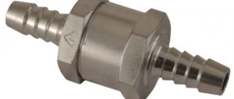
Any check valve (OC) is nothing more than an element that ensures the movement of fuel in one direction.
It can block the flow of unused fuel back into the fuel tank. Its design, as a rule, implies the presence of a calibrated saddle made of soft metal. The valve allows gasoline or diesel fuel to pass in one direction, but when the engine stops, the valve automatically closes and the movement of liquid stops.
Fuel system valve and pipe
Despite the simplicity of the design of the bypass valve, its malfunction or its banal absence in the system can lead to great difficulties. For example, the normal functioning of the motor is impossible, and starting it becomes more difficult.
There is no need to confuse the OK with a pressure reducing valve. The latter is responsible for pressure stability, although it operates in conjunction with a check valve.
Read more about pressure reducing valve. It is responsible for equalizing the pressure in the section of the fuel rail where the fuel liquid enters the injectors. If it were not for this valve, the injectors would receive fuel under different pressures or without it, as a result of which they would not be able to transfer gasoline further into the chamber.
Pressure reducing valve or pressure regulator
The regulator stops supplying fuel to the injectors when the engine stops and the ignition is turned off. The shut-off mechanism simply operates, cutting off part of the fuel line. Gasoline remains only in the area between the fuel pump and the ramp, if OK. If not, there will be no fuel in the system; it will leak back into the tank.
Pressure relief valve - diagram and device
Figure No. 2 shows a brief diagram of the operation and design of the mechanical emergency fuel dump valve. These valves are mechanical (direct-acting), less common are electro-mechanical valves (indirect-acting). Mechanical safety valves, such as our example, include:
- Housing with external thread for installation in the fuel rail.
- Drain channel for fuel return.
- Plunger with a conical part.
- Return spring.
Source
Fuel system common rail KAMAZ
The Common Rail (CR) fuel supply system allows for a wider range of fuel injection requirements, namely:
- increased injection pressure;
- variable injection start point;
- providing pre- and post-injection;
- regulation of injection pressure depending on the operating conditions of the KamAZ engine and the vehicle.
The Common Rail fuel supply system contains:
- electronic control unit;
- sensors (see Fig. Installation of sensors on an engine with a Common Rail fuel supply system):
- fuel pressure sensor in the high pressure fuel accumulator (“Rail”);
- camshaft position sensor;
- fuel temperature and pressure sensor;
- oil temperature and pressure sensor;
- coolant temperature sensor;
- charge air temperature and pressure sensor;
- crankshaft position sensor;
- an injector with a high-speed solenoid valve that regulates the fuel injection process in each cylinder;
- high pressure fuel pump (HPF) with a fuel flow regulator and a fuel priming pump.
- auxiliary brake system button. On vehicles with KAMAZ engines with a Common Rail fuel supply system, the auxiliary braking system is activated when driving at a speed of at least 30 km/h.
- cruise control/speed limit switch;
- engine diagnostic mode switch;
- engine diagnostic warning lamp;
- fuel pedal;
- brake pedal sensor;
- parking brake sensor;
- engine emergency stop valve;
- clutch pedal sensor.
Bosch injection pump check valve for KAMAZ
KAMAZ EURO-2 stalls while driving
Check valve for injection pump BOSCH VE
Man tga. Repair. Injection pump check valve.
How to Test a Fuel Check Valve
Kamaz troit stalls
Checking a faulty and serviceable Bosch VP30 injection pump valve on the engine and on the stand
Injection pump Bosch Kamaz Euro 2
KamAZ injection pump drive Part 2.
Injection pump return valve Euro 2 VG2600080213
modification of the Mitsubishi Pajero injection pump return valve (Mitsubishi Pajero), with a 4m40 engine for Kamaz
Also see:
- Locker for KAMAZ 4308
- Body parameters of KAMAZ 53212
- Convert KAMAZ gearbox to MAZ
- KAMAZ lift hydraulic cylinder
- How to remove the rev limiter on a KAMAZ
- KAMAZ in the mud is cool
- KAMAZ odometer winder
- How to align brake pads on a KAMAZ video
- Electrical diagram of KAMAZ 65117 with cummins engine
- Remove the boiler from KAMAZ
- Lubrication of KAMAZ chassis
- Stocking air filter KAMAZ
- Bearing 306 KAMAZ
- KAMAZ accident at a crossing
- Specification KAMAZ 55102
Home » New items » Bosch injection pump check valve for KAMAZ
kamaz136.ru
Injector repair kit.
Already in the mode of cranking the crankshaft with the starter, the injection pump creates a starting pressure of 350–400 bar. At minimum idle speed - up to 500-600 bar, and at maximum load - up to 1300-1500 bar. There are pumps with pressure up to 2000 bar. Its value is set by a regulator located on the fuel injection pump housing or on the ramp and subordinate to the electronic engine control unit. When issuing commands, the ECU relies on signals from the rail pressure sensor.
Fuel is supplied through high-pressure pipes to the injectors, which open under the influence of an electrical signal. There are two design options - electromagnetic or with a piezoelectric element. The first one was not particularly fast at first, which forced the designers to look for an alternative. In a piezo injector, voltage is applied to a piezo crystal, which instantly expands. The spool compresses the spring, the injector needle opens the way for fuel - and it is injected into the combustion chamber. However, designers continue to improve electromagnetic devices - both options work successfully on modern engines.
Fuel supply system
FUEL SUPPLY SYSTEM The FUEL SUPPLY SYSTEM ensures fuel filtration and its uniform distribution throughout the engine cylinders in measured portions at strictly defined moments.
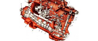
Figure 34 — Fuel supply system with V-shaped injection pump
1…4, 9…12 - high pressure fuel lines; 5 - nozzle; 6 - injection pump; 7 — fuel pump; 8 — outlet pipe of the fuel priming pump; 13 — electromagnetic valve; 14 - valve; 15 - FTOT; 16 — fuel supply pipe to the injection pump; 17 — EFU fuel tube; 18 — bypass valve; 19 — EFU valve; 20 — fuel drain pipe for right-hand injectors; 21 — fuel pipe from the solenoid valve to the EFU spark plugs; 22 - tee; 23 — EFU spark plug; 24 — fuel drainage pipe for left-hand injectors; 25 — filling neck with mesh filter; 26 — fuel tank; 27 — fuel intake pipe with strainer; 28 — fuel pre-filter; 29 — manual fuel pump; 30 — actuator position sensor; 31 - tee; 32 — reservoir of the PZD system.
The engines use split-type fuel supply systems, consisting of a fuel tank, low- and high-pressure fuel lines, a fine fuel filter (FFP), a coarse fuel filter (FGOT), fuel priming and pre-priming pumps, and a high-pressure fuel pump (HPF) , electronic control system (ECS), pedal module, injectors, solenoid valve and pin spark plugs of the electric torch device (EFD).
The fuel tank, coarse fuel filter, fuel pre-priming pump, electronic control unit and pedal module are installed on the product on which the engine is used, all other elements of the power system are installed directly on the engine. A description of the design and maintenance requirements for units installed on the product are given in the product manual.
Figure 35 — Fuel supply system with in-line injection pump “BOSH”:
1…8 - high pressure fuel lines; 9 — fuel drainage pipe of the left head injectors; 10 - nozzle; 11 — fuel drain pipe for right-hand injectors; 12 — fuel outlet pipe from the injection pump; 13 — fuel outlet pipe of the fuel priming pump; 14 — fuel pipe supplying the injection pump; 15 — electromagnetic valve EFU; 16 - FTOT; 17 — EFU spark plug; 18 — fuel pump; 19 — fuel pipe to the solenoid valve; 20 — fuel pipe from the solenoid valve to the EFU spark plugs; 21 - injection pump; 22, 33 — tee; 23 - valve; 24 — fuel injection pump bypass valve; 25 — retractor solenoid of the stop valve; 26 — fuel tank; 27 — filling neck with mesh filter; 28 — fuel intake pipe with strainer; 29 — fuel pre-filter; 30 — manual fuel pump; 31 — electronic speed controller of the fuel injection pump; 32 — reservoir of the PZD system.
The diagram of the engine power supply system with a V-shaped injection pump is shown in Figure 34.
Fuel from the fuel tank 26 through the pre-cleaning filter 28 and the manual fuel pump 29 is supplied by the fuel priming pump 7 through the fuel pipe 8 to the fine filter 15. From the fine filter through the low-pressure fuel pipe 16, the fuel enters the injection pump 6, which, in accordance with the procedure cylinder operation, distributes fuel through high-pressure fuel lines 1...4, 9...12 to injectors 5. The injectors inject fuel into the combustion chambers. Excess fuel, and along with it the air that has entered the system, is discharged into the fuel tank through bypass valve 18 and valve 14.
The diagram of the engine power supply system with an in-line injection pump is shown in Figure 35. The given diagrams are similar and differ in the units included in them and the location of the fuel lines.
NOZZLES manufactured by "YAZDA" (Figure 36a) and "AZPI" (Figure 36b) are of a closed design, with six spray holes and hydraulically controlled lifting of the spray needle. All parts of the nozzle are assembled in housing 9. The nozzle body 1, inside of which there is a needle 2, is pressed to the lower end of the nozzle body with a nut 3 through a spacer 4. The body and the nozzle needle form a precision pair. The angular fixation of the nozzle body relative to the spacer and the spacer relative to the nozzle body is carried out with pins. Spring 6 exerts pressure on the upper end of the spray needle through rod 5. The required force of this spring is provided by a set of adjusting washers 7 installed between the spring and the end of the internal cavity of the nozzle body. The end of the nut 3 of the nozzle is sealed against gas breakthrough with a corrugated copper gasket. O-ring 8 protects the cavity between the nozzle and the cylinder head from dust and liquids.
Figure 36 - Injectors:
1- spray body; 2 — spray needle; 3 — sprayer nut; 4 — spacer; 5 — nozzle rod; 6 — nozzle spring; 7 — adjusting washers; 8 - sealing ring; 9 — nozzle body; 10 - slot filter; 11- nozzle fitting a - “YAZDA”, b - “AZPI”:
Fuel is supplied to the injector under high pressure, passes through the slot filter 10, then through the channels of the housing 9, spacer 4 and sprayer body 1 enters the cavity between the sprayer body and needle 2. The fuel flows under high pressure from the injection pump sections to the injectors, overcoming the pressure the force of the injector spring lifts the nozzle needle and is injected into the combustion chamber through the spray holes.
Fuel that has leaked through the gap between the needle and the nozzle body is discharged through channels in the nozzle body and drained into the fuel tank through the injector drain tubes.
Each injector 1 (Figure 37) is installed in the cylinder head 2, fixed by a cast bracket 3, which is secured by a nut 5 with a spherical washer 4. The tightening torque of the nut 5 is 35...40 Nm (3.6...4.1 kgf-m) .
ATTENTION!
Checking and adjusting nozzles, as well as replacing nozzles, must be carried out in a specialized workshop by a qualified specialist.
It is strictly prohibited to install injector models not listed in Table 1 of this manual, due to the possibility of engine failure!
Figure 37 - Installing the fuel injector:
1 - nozzle; 2 - cylinder head; 3 — nozzle mounting bracket; 4 — spherical washer; 5 - nut; 6 — hairpin; 7 — bracket support; 8 - sealing ring.
HIGH PRESSURE FUEL PUMPS are designed to supply strictly dosed portions of fuel under high pressure to the engine cylinders at certain moments. In this case, fuel is supplied to the engine cylinders at strictly defined angles of rotation of the engine crankshaft.
KAMAZ engines use:
— V-shaped injection pump mod. 337-23 produced by JSC YaZDA with an electronic engine control system
— in-line injection pump mod. P7100 produced by f. "BOSH" (Germany) with mechanical or electronic regulators.
Figure 38 - V-shaped injection pump:
1 — fuel injection pump housing; 2 - pusher; 3 - cracker; 4 — pusher spring; 5 - rotary sleeve; 6 - plunger; 7- rack; 8 — fuel injection pump section housing; 9 — plunger bushing; 10 — discharge valve body; 11 — discharge valve; 12 — fitting; 13 — fuel priming pump; 14- IM connector; 15- upper regulator cover; 16 — rack lever; 17 — MI position sensor; 18 — actuator (AM); 19 — bypass valve; 20 — rack plug; 21 - bearing; 22 — adjusting shims; 23 - cam shaft; 24 — eccentric drive of the fuel pump; 25 — rear regulator cover; 26 — return spring IM; 27 - fuel temperature sensor.
The injection pump is located in the camber of the engine cylinder block. Its drive is carried out from the engine crankshaft through a set of gears using a drive shaft, driving and driven coupling halves with elastic plates that compensate for the misalignment of the drive parts and the fuel injection pump cam shaft.
A fuel priming pump is combined with a high-pressure fuel pump in one unit.
The V-shaped injection pump used on engines is shown in Figure 38.
In the bore of the lower part of the housing there is a cam shaft 23 with tapered roller bearings 21 pressed onto it. The cam shaft is secured against axial movement by two covers. Adjusting shims 22 are installed under the bearing caps, which adjust the tension in the bearings, which should be 0.05 ... 0.10 mm.
Pushers 2 are installed in the body bores, consisting of a pusher body, a roller, a bushing and an axis, which is fixed relative to the pusher body with a pin. The pusher assembly is secured against rotation in the fuel injection pump housing using a special lock 3.
Eight removable assembled sections are installed in the body bores. Each section consists of a section body 8, a rotary sleeve 5, a sleeve 9 with a plunger 6 and a discharge valve 11, pressed by a fitting 12 to the plunger sleeve.
The plunger 6 is driven from the cam shaft by means of a pusher. Spring 4 through the plate constantly presses the pusher roller to the cam, which ensures reciprocating movement of the plunger. Plunger diameter 12 mm.
The plunger pair serves to create fuel pressure at the injector and change the amount of fuel supplied to the engine combustion chamber per cycle. Fuel dosing is carried out by simultaneously changing both the beginning and the end of the fuel injection cycle.
The plunger sleeve has two windows located at the same level, which simultaneously serve for filling and cutting off fuel. When the plunger is in the lower position, fuel flows through both windows into the cavity above the plunger. When moving upward, at the moment the windows are blocked by the upper edge of the plunger, the active stroke of the plunger begins, during which fuel is forced out into the discharge pipeline.
To change the start of injection depending on the load, a specially shaped control edge is made at the upper end of the plunger. When the screw edges of the plunger begin to open the windows, the active stroke ends, fuel begins to flow into the shut-off cavity, the pressure in the above-plunger cavity drops sharply and fuel injection stops.
To change the amount of injected fuel, the plunger is rotated around its axis using a rotary sleeve, which is connected to the fuel injection pump rack.
So, with the help of the control edge, the start of the fuel supply is changed, and with the help of the cut-off edges, the cut-off moment is changed. In this case, not only the angles of the beginning and end of the feed change, but also the amount of injected fuel
The operating principle of in-line pumps is similar.
The installation of an in-line pump with a mechanical regulator on the engine and its connection with the motor systems is shown in Figure 39. The installation of a pump with an electronic regulator is similar, but there are no regulator and stop levers, as well as bolts limiting their movement.
ATTENTION!
Inspection, adjustment and repair of fuel injection pumps may only be carried out in specialized workshops of service centers by qualified personnel.
Check and maintain V-shaped injection pumps once every two years (see Table 11). Maintenance of fuel injection pump f. "BOSH" is not carried out if the operating requirements are met.
In order to avoid deterioration in the quality of the working process in the engine, increasing the toxicity and smoke of exhaust gases, as well as engine failure, it is strictly prohibited to install fuel injection pump models on engines not listed in Table 1 of this manual.
Figure 39 — Installation and external connections of a BOSCH in-line injection pump with a mechanical regulator:
1 — fuel priming pump; 2 — minimum speed limit bolt; 3 — regulator lever; 4 — bolt for limiting maximum speed; 5 - stop lever.
FINE FUEL CLEANING FILTER (Figure 40) is designed for final cleaning of fuel from small particles before entering the injection pump. The filter is installed at the highest point of the fuel supply system to collect and remove air into the tank along with part of the fuel through a valve that is installed on the bypass from the filter.
ATTENTION!
When replacing filter elements, you must strictly follow the rules for servicing the fuel supply system. Do not allow contaminants to enter the power system and use filter elements only of the following models: 740.1117040-01, 740.1117040-02, 740.1117040-04.
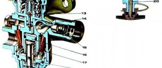
Fine fuel filter VALVE 13 is shown in Figure 40. The valve is designed to remove air accumulating in the upper part of the fine fuel filter, as well as to protect the filter elements from rupture. When the pressure in cavity “B” of the fuel supply reaches 25…80 kPa (0.25…0.80 kgf/cm2), ball 15 moves and fuel flows from cavity “B” to cavity “A” through valve nozzle 16. At a pressure of 200…240 kPa (2.0…2.4 kgf/cm2), the valve is fully opened and fuel is bypassed into the fuel tank through cavity “A”. During normal engine operation, the air that accumulates in the upper part of the FCTF, together with part of the fuel circulating in the low-pressure line, is pumped through the valve into the fuel tank. Fuel consumption is limited by nozzle 16. When the filter elements are clogged to critical values, the pressure in cavity B increases, which leads to significant fuel consumption through the nozzle. As a result, the engine loses power and stops.
Figure 40 — Fine fuel filter:
1 - body; 2 - bolt; 3 - sealing washer; 4- plug; 5, 6- gaskets; 7 - filter element; 8 — cap; 9- spring; 10 - drain plug; 11 — rod; 12 - nut; 13 - valve body; 14 — valve spring; 15 - ball; 16 - jet; A - fuel outlet cavity; B - fuel supply cavity.
FUEL SUPPLY PUMP 7 (Figure 34) or 18 (Figure 35) piston type, designed to supply fuel from the tank through pre- and fine filters to the injection pump plunger pairs.
The pump is installed on the fuel injection pump. The pump operation diagram is shown in Figure 41. The body of the fuel priming pump contains: a piston, a piston spring, a pusher, inlet and discharge valves with springs. The reciprocating movement of the piston 1 is carried out under the action of a pusher 9 located on one side of the piston and a spring 4 on the other side.
The fuel priming pump operates only when eccentric 8 rotates, i.e. when the injection pump cam shaft rotates.
When piston 1 moves upward under the action of pusher 9, the fuel, overcoming the force of spring 6, opens valve 5 and enters cavity “A” from cavity “B” (under the piston). Valve 2 is closed.
When the pusher 9 is lowered, the piston 1 moves downward under the action of the spring 4. A vacuum is created in cavity “B” and inlet valve 2, compressing spring 3, passes fuel from the fuel supply line “G” into cavity “B”. At the same time, the fuel located in the discharge cavity “A” is forced into the fuel outlet pipe “B”, while valve 5 closes under the action of spring 6, preventing fuel from flowing from cavity “A” to cavity “B”.
Figure 41 — Scheme of operation of the fuel priming pump:
1 - piston; 2 — inlet valve; 3, 6 — valve springs; 4 — piston spring; 5 - discharge valve; 7- pusher spring; 8 - eccentric; 9 — pusher; A - injection cavity of the fuel priming pump; B - suction cavity of the fuel priming pump; B — fuel outlet pipe (to FTOT); G - fuel supply line (from the fuel pre-filter).
FILTER FOR PRELIMINARY (COARSE) FUEL CLEANING
In the fuel systems of KAMAZ engines, in order to increase their reliability, coarse (preliminary) fuel filters must be used with a degree of purification from particles of mechanical impurities up to 30 microns in size of at least 95% and water at least 93%. The PreLine 270 filter, shown in Figure 42, meets these requirements.
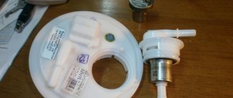
The fuel pre-filter consists of a housing 5, on which are installed: a manual fuel pump 3 of the membrane type, a replaceable filter element (filter cartridge) 8 with a water collection cup 9, an electric fuel heater 6, which may not be installed when operating in tropical climates, then a plug is installed instead.
Unpurified fuel from the tank is supplied through fuel pipes to the inlet channel 1 of the fuel pre-treatment filter, then to the filter cartridge, where water is separated and purified from mechanical impurities and solid particles larger than 30 microns in size. Mechanical impurities, solid particles and water are retained by the filter element of the replaceable filter cartridge and accumulate in the drainage cup. The purified fuel enters the cavity of the exhaust channel 7 and then through the fuel pipes into the fuel priming pump.
Before starting the engine after a long stop and after changing the filter cartridge, air is removed from the cavities of the fuel pre-cleaner. To do this, loosen the air bleed screw 4 and pump the fuel with a hand pump 3 until fuel comes out of the air bleed screw hole without air, after which tighten the screw.
During operation, it is necessary to drain the sludge daily by turning screw 10 located at the bottom of the drainage cup.
It is recommended to change the filter cartridge (order number: 66 604 58 190) after one maintenance service (32...33 thousand km of vehicle mileage) or more often if there is a drop in engine power due to the use of low-quality (contaminated) fuel. The replacement procedure is presented on the body of each filter cartridge in the form of drawings and inscriptions.
Figure 42 — Fuel pre-filter PreLine 270 f. “MANN+HUMMEL”: 1 — inlet channel; 2 — membrane cover of the manual fuel pump (TPP); 3 — manual TPN; 4 — air bleed screw; 5 — body; 6 — electric heater; 7, 11 — exhaust channel; 8 — replaceable filter element; 9 — drainage glass; 10 - water drain screw.
When operating in countries with cold climates, the PreLine 270 filter is equipped with a built-in electric fuel heater 6 with a power of 350 W, which prevents paraffin formation at low ambient temperatures. The heater automatically turns on at a fuel temperature of +5°C.
An alternative version of the PreLine 270 fuel pre-cleaner (Germany), used on KAMAZ engines, is the RACOR SK 1969 (USA) fuel pre-cleaner, which has a similar design and similar technical characteristics. The filter features a manual fuel pump design, a 300 W electric heater power and a replaceable filter cartridge (order no.: 66 604 58 190). For work in countries with a tropical climate, the RACOR SK 1967 filter is used (without an electric fuel heater).
FUEL PIPES are divided into low pressure fuel lines - 0.4...2.0 MPa (4...20 kgf/cm) and high pressure - more than 30 MPa (300 kgf/cm).
Low-pressure fuel lines for engines are made of steel pipe with a cross-section of 10x1 mm with soldered tips, and high-pressure fuel lines are made of steel pipes with an internal diameter of 2 mm and an outer diameter of 7 mm with nuts and conical tips. To avoid damage from vibration, the fuel lines are secured with brackets to the intake manifolds.
The injection pump drive is shown in Figure 43. It consists of a fuel injection pump drive shaft 8 with packages of front 4 and rear 6 compensating plates, a driven coupling half 2, a driven coupling half flange 3, a centering flange 5, a driving coupling half 10 and centering bushings 13. Each package of compensating plates consists of 6 plates, each 0.5 mm thick, made of 65G steel.
FUEL SUPPLY SYSTEM MAINTENANCE
During engine operation and especially in its initial period, it is necessary to regularly check the tightening torque of nut 5 (Figure 37) securing the injector brackets and bolt 11 (Figure 43) of the drive coupling half of the injection pump drive.
Regularly drain sediment from fine and pre-filter fuel filters. The procedure for servicing the fuel pre-cleaning filter is given in the filter description. To drain water from the fine fuel filter, unscrew drain plugs 10 two or three turns (Figure 40). Drain the sludge until clean fuel appears.
It is recommended to change the filter elements of the fine fuel filter every 20,000 km of the product or 560 hours of engine operation, for which:
— unscrew the drain plugs two or three turns and drain the fuel from the filter caps into a container, then screw in the plugs;
- unscrew the bolts securing the filter caps, remove the caps and remove the dirty filter elements;
- wash the caps with diesel fuel;
-install a new filter element with sealing gaskets into each cap, install the caps with filter elements and tighten the bolts;
— bleed the system with a pre-fuel pump;
- Start the engine and make sure the filter is tight.
Eliminate fuel leakage by tightening the cap mounting bolts.
Inspection and maintenance of fuel injection pumps should be carried out at specialized and certified service centers, KAMAZ OJSC and.
The fuel injection start pressure of the injectors is adjusted on the bench by installing adjusting washers under the spring with the nut, nozzle, spacer and rod removed. As the total thickness of the shims increases (increased spring compression), the injection start pressure increases. A change in the thickness of the washers by 0.05 mm leads to a change in the injection start pressure by 0.30...0.35 MPa (3.0...3.5 kgf/cm2).
The number of installed washers should be no more than three.
Injection start pressure - according to the requirements of Table 1.
The beginning and end of fuel injection must be clear. The sprayer must not leak. The injection should be accompanied by a characteristic sound. Replacement of any one part (atomizer body or needle) is not allowed, since they form a precision pair.
After maintenance and repair, V-shaped and in-line injection pumps are installed on the engine in the following sequence:
1 Assemble the injection pump with the drive shaft according to Figure 43, depending on the engine configuration, in this case it is necessary to align the installation mark on the flange of the driven coupling half with the pointer on the injection pump housing. The permissible shift of the installation mark towards increasing the fuel injection advance angle is no more than 2 mm.
2 Fill the injection pump (check the level) with engine oil used on the engine to the level of the drain hole.
3 Install the retainer into the flywheel groove. In this case, the mark on the part pos. 2 should be located at the top, and key 12 should be located in a horizontal plane on the side of the eighth cylinder. Install the drive coupling half onto the shaft of the driven gear of the injection pump drive without tightening the coupling bolt.
4 Install the injection pump with drive onto the engine. Tighten the bolts securing the injection pump to the cylinder block using a cross method in two steps. Tightening torques are given in Appendix A.
The fuel injection pump with drive in the camber of the cylinder block must be secured without distortions.
5 Secure the package of rear plates of the injection pump drive with bolts 10, having previously installed the centering bushings 13 in them.
6 Tighten the coupling bolt 11 last. To do this, it is necessary to loosen it so that the drive coupling half can move freely along the shaft and take an optimal position, eliminating axial stress and deformation (bending) of the front and rear plates. After this, tighten the coupling half mounting bolt.
7 After completing the installation and adjustment, install the flywheel lock handle into the shallow groove on the lock body.
8 Tighten the nuts of the high pressure fuel lines
Figure 43 — Installation of the injection pump drive on engines:
1 — fuel injection pump housing; 2 — driven coupling half; 3 — flange of the driven coupling half; 4, 6 — packages of compensating plates; 5 — centering flange; 7.9 — fastening bolts; 8 — drive shaft; 10 — driving coupling half; 11 — bolt of the drive coupling half; 12 - key; 13 — centering sleeve; 14 - bearing 306 in the crankcase of the units. S - permissible shift of the installation mark in the direction of increasing the fuel injection advance angle of no more than 2 mm.
Check the installation and adjustment of the fuel injection advance angle using a momentoscope in the following order:
1 Disconnect the high pressure pipe from the eighth section of the injection pump.
2 Install a momentoscope on the fitting of the eighth section.
3 For engines with a V-shaped injection pump with an electronic regulator, using special diagnostic equipment and the computer, set the rack position corresponding to 100% movement (controlled by the rack position sensor).
For engines with an in-line injection pump with an electronic regulator, using special diagnostic equipment and the computer, set the voltage of the electrical signal of the injection pump rack position to 4.7 V.
For engines with an in-line injection pump with a mechanical regulator, move the regulator control drive lever 3 to the middle position (Figure 39).
4 Fill the engine fuel system with fuel using a bench fuel pump.
5 Rotating the engine crankshaft, fill the glass tube of the momentoscope with fuel (ATTENTION! Rotate the crankshaft only by hand).
6 Rotating the engine crankshaft, align the installation mark (mark) of the driven coupling half flange with the pointer on the injection pump housing (Figure 43).
7 Rotate the engine crankshaft half a turn against the direction of rotation (clockwise when viewed from the flywheel).
8 Move the flywheel lock into the deep groove and slowly turn the engine crankshaft in the direction of rotation until the fuel begins to move in the glass tube of the momentoscope or until the lock enters the flywheel groove.
If, at the moment the fuel begins to move in the glass tube of the momentoscope:
— the retainer has entered the groove of the engine flywheel;
— the installation mark of the driven coupling half flange and the pointer on the fuel injection pump body coincide (the mark may not coincide with the pointer by no more than 2 mm in the direction of fuel injection advance);
— the head of the coupling bolt 11 of the drive coupling half is located as shown in Figure 43, then the fuel injection advance angle is set correctly, move the lock into a shallow groove.
If, at the moment the fuel begins to move in the glass tube of the momentoscope, the groove of the engine flywheel has not reached the latch, loosen the bolts securing the driven coupling half and slowly turn the crankshaft in the direction of rotation until the latch fits into the groove of the flywheel, tighten the bolts securing the driven half coupling, move the latch into the shallow groove and check the accuracy of setting the fuel injection advance angle.
If the latch has entered the groove of the engine flywheel, and the fuel in the glass tube of the torque scope has not moved, it is necessary to move the latch into a shallow groove and slowly turn the crankshaft in the direction of rotation until the fuel begins to move in the glass tube of the momentoscope, loosen the bolts securing the driven coupling half, and turn the crankshaft against the direction of rotation 4... 10° further than the lock, move the lock into a deep groove and slowly turn the crankshaft in the direction of rotation until the lock enters the groove of the flywheel, tighten the bolts securing the driven coupling half, move the lock into a shallow groove and check the accuracy of setting the fuel injection advance angle .
9 Check the accuracy of setting the fuel injection advance angle, for which:
— turn the crankshaft 1.5 turns in the direction of rotation;
— move the flywheel lock into the deep groove;
- slowly turning the crankshaft as it rotates, carefully monitor the fuel level - the flywheel lock should enter the groove of the engine flywheel at the moment the fuel begins to move in the glass tube of the momentoscope. In this case, the installation mark of the driven coupling half flange and the pointer on the fuel injection pump housing must coincide (the mark may not coincide with the pointer by no more than 2 mm in the direction of advancing fuel injection);
— Move the flywheel lock into a shallow groove.
Setting the fuel injection advance angle using a momentoscope is a priority.
In the absence of a momentoscope, it is possible to check the installation and adjust the fuel injection advance angle according to the marks. To do this, after first turning off the fuel supply and braking the product, perform the following operations:
1 Check the accuracy of setting the fuel injection advance angle, for which:
— rotate the crankshaft until the installation mark of the driven coupling half flange aligns with the indicator on the injection pump housing (Figure 43);
— turn the crankshaft half a turn against the direction of rotation (clockwise, when viewed from the flywheel);
— move the flywheel lock into the deep groove and slowly turn the crankshaft in the direction of rotation until the lock enters the flywheel groove.
If at this moment:
— the installation mark of the driven coupling half flange and the pointer on the fuel injection pump body coincide (the mark may not coincide with the pointer by no more than 2 mm in the direction of fuel injection advance);
— the head of the coupling bolt 11 of the drive coupling half is located as shown in Figure 43, then the fuel injection advance angle is set correctly, move the lock into a shallow groove.
2 If there is a mismatch (taking into account a tolerance of 2 mm) between the installation mark of the flange of the driven coupling half and the pointer on the injection pump housing at the moment when the latch enters the groove of the flywheel, it is necessary to adjust the fuel injection advance angle, for which:
— loosen the bolts securing the driven coupling half flange;
— slowly turn the flange of the driven coupling half until the installation mark aligns with the pointer on the injection pump housing;
— tighten the bolts securing the driven coupling half flange;
— move the flywheel lock into a shallow groove;
— check the accuracy of setting the fuel injection advance angle according to point 1.
Check the tightness of the injection pump drive bolts with a torque wrench.
Stand for testing injectors and high pressure pumps.
If the timing drive is in order, we proceed to checking the fuel supply. The electric booster pump comes into operation with the turn of the key. When this pump wears out or is damaged, the power it consumes changes; the ECU records this as a malfunction and records its code in the system memory. But you shouldn’t rely completely on electronics, so we connect the pressure gauge to the low pressure line. (For ease of control, the mechanical booster pump has a fitting.) If the pressure here is normal, we move on to the injection pump.
Let's check the fuel pressure in the rail while cranking the crankshaft with the starter. This part of the system is equipped with a fuel pressure sensor, so we will use its services. We connect the scanner to the diagnostic connector and find the desired parameter. If it is below normal, we look for where the fault is hidden. The culprits may be injectors, solenoid valves (regulators) and the fuel injection pump itself.
Diagram of the common rail diesel power system:
740.70-1104000 Installation of fuel lines - KamAZ-65111 (Euro 4):
4 4 4 4 4 6 6 6 6 6 6 6 8 10 12 14 16 16 18 20 22 24 26 28 28 28 30 32 34 36 40 42 44 48 50 52 54 56 56 58 62 64 66 66 68 68 72 72 74 76 82 84 86 86 88 88 88 88 88 88 88 90 92 94 94 96 98 100 100 100 102 104 106 108 108 108 108 108 108 110 112 114 116 120 122 124 126 128 128 130
List of components from 740.70-1104000 Installation of fuel lines on KamAZ-65111 (Euro 4)
Parts diagrams are for reference purposes only! We do not sell all spare parts from 740.70-1104000 Installation of fuel lines for KamAZ-65111 (Euro 4) presented in this list. If there is a link “Show prices” in the right column, these spare parts from “740.70-1104000 Installation of fuel lines” are on sale. Availability in warehouses for details and prices, see the product card. If there is no “Show cost” link in the right column, we do not sell such parts and do not accept orders for them.
| № | Part code | Name | Quantity per model, pcs. | Show all prices | |
| 4 | 740-70-1104232 | Fitting assembly | 3 | Show prices | |
| Retail | — + | ||||
| 6 | 740-70-1104234 | Fitting assembly | 5 | Show prices | |
| Retail | — + | ||||
| — + |
| — + |
| — + |
| — + |
| — + |
| — + |
| — + |
| — + |
| — + |
| — + |
WE REPAIR
Restoring the pump's functionality can only be done by a specialized workshop with qualified personnel and diagnostic equipment. The cost of repairs is from 7 thousand rubles, then it depends on the complexity. In case of some damage, it is wiser to buy a new injection pump. The usual price, about 30 thousand rubles, will shock the tight-fisted diesel operator, which is why repaired or restored products are in use.
A CR diesel with high mileage is often impossible to start due to a malfunction of at least one of the injectors. Fuel leakage through its valve does not allow the pressure in the rail to rise to starting values. There is a special diagnostic kit to check the pressure at start-up. It includes a control pressure gauge, a pressure sensor, connection tubes, plugs instead of actuators and backflow measuring containers.
A cutaway view of a high-pressure fuel injection pump with a plunger section shut-off valve.
It is reasonable to replace worn out injectors as a set. The price range is very wide: depending on the model and manufacturer, they cost from 8 thousand to 25 thousand rubles. a piece. The characteristics of each new injector must be recorded in the memory of the engine control unit, because no two injectors have the same performance. Different ones not only have a bad effect on the uniformity of engine operation and its dynamic loads, but also worsen the characteristics of the car. Although each ECU has dynamic adaptation (constant adjustment of the cyclic fuel supply for smooth engine operation), you need to remember that it cannot replace the coding if, for example, you forgot to write it down.
The problem of difficult starting of a diesel engine is one of the most common. And the owner is sometimes dissatisfied, for example, with reduced engine power or exhaust smoke. These problems are the most complex, because they require an assessment of the accuracy of measuring air flow or supercharging operation, the efficiency of recirculation, the exhaust gas system, including the diesel particulate filter (DPF) and the converter. However, these technologies are now well mastered by diagnostic masters.
Source