Symptoms of malfunction of fuel injection pump KAMAZ 740, fuel injection pump KAMAZ 4310
Malfunctions of fuel pumps and regulators manifest themselves in a violation of adjustment due to wear of parts, which results in the occurrence of extraneous noise, overheating and fuel leakage.
The main reason for the malfunction of the fuel pump is wear of its parts, weakening of the tightness in the fits, increased gaps in the moving joints, violation of the location of the parts, and deposits on the surface of the parts in the form of dirt and carbon deposits.
The consequence of pump malfunctions can be a decrease in the supply of fuel in the required quantity and uneven supply. Failure to properly supply fuel is usually caused by wear of plunger pairs, pump discharge valves, plunger drivers, rack clamps, rack teeth and bushing gears, and clogging of injectors. Such malfunctions lead to a decrease in engine power and efficiency.
Uneven supply of fuel to the engine cylinders will lead not only to unstable operation at low speeds, but also to interruptions in the operation of individual cylinders, which will be accompanied by vibration of the engine block.
Fuel injection pump malfunctions include uneven start of injection and delay in injection timing of a multi-section pump, which occurs due to wear of the pusher adjusting bolt, roller axis, pusher and roller housing, ball bearings, as well as wear of the cam shaft.
Wear of plunger pairs and injection valves significantly affects the change in the fuel injection advance angle.
- The KAMAZ engine does not start or starts poorly;
- Uneven operation of the KAMAZ engine;
- During operation, noises and knocks from the KAMAZ engine occur.
Fuel injection pump of diesel engine D-245 - design and adjustments
On the D-245 engine of the ZIL-5301 Bychok, GAZ-3309, MAZ-4370 Zubrenok cars, fuel injection pumps-773 are installed. The high-pressure fuel pump is a block design consisting of four pump sections in one housing, having a cam drive of plungers and spool-type dosing of cyclic fuel supply.
TNVD-773 is designed to supply metered portions of fuel under high pressure into the combustion chambers of diesel cylinders at certain points in time. The fuel pump camshaft is driven from the diesel crankshaft through distribution gears.
The relative position of the fuel pump drive gear and the drive coupling half is fixed by tightening the nuts installed on the coupling half studs. The tightening torque of the nuts is 35…50 Nm.
The D-245 high-pressure fuel pump is combined into one unit with an all-mode regulator and a piston-type fuel priming pump.
The regulator has a fuel supply corrector, an automatic fuel enricher (at starting speeds) and a pneumatic smoke limiter (boost corrector). The booster pump is installed on the fuel injection pump housing D-245 and is driven by the cam shaft eccentric.
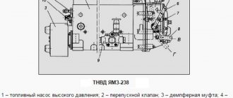
The working parts of the pump are lubricated with flowing oil coming from the diesel lubrication system. The oil is drained from the pump housing into the diesel crankcase. The newly installed pump on a diesel engine must be filled with oil in the amount of 200…250 cm3. Fill oil through the oil drain hole pos. 30 (Fig. 1).
Fig. 1 – Fuel pump TNVD 773 diesel D-245
1 - fuel pump section; 2 — plate; 3 – flange; 4 – key; 5 – drive coupling half; 6 – nut for fastening the coupling half; 7 – cam shaft; 8 – fuel pump housing; 9 – fuel priming pump; 10 – supporting bracket; 11 – starting feed adjustment bolt; 12 – stop lever; 13 – regulator body; 14 – regulator cover; 15 – inspection hatch cover; 16 – minimum rotation speed adjustment bolt; 17 – bolt for adjusting the maximum rotation speed; 18 – nut securing the fuel pump sections; 19 – bypass valve; 20 – fuel supply fitting; 21– oil line; 22 – fuel outlet fitting from the booster pump to the fine fuel filter; 23 – bolt securing the fuel supply fitting to the booster pump; 24 – boost corrector; 25 – bolt of the air supply fitting; 26 – control lever; 27 – screw plug for adjusting the nominal fuel supply; 28 – air bleed plug; 29 – stop electromagnet; 30 – oil drain hole.
Maintenance of the high pressure fuel pump TNVD diesel engines D-245
During operation of the high-pressure fuel pump 773, when the main parts wear out, its adjustment parameters are violated. Injection pump lubricant D-245 is centralized from the diesel lubrication system through a special oil line. The required oil level in the pump crankcase is set automatically.
To reduce wear of precision parts, it is not allowed to operate the injection pump without a filter element or with a clogged fine fuel filter. It is also not allowed to work with fuels that have a high water content.
If necessary, and also every 120 thousand km, it is necessary to remove the pump and check it on a stand for compliance with the adjustment parameters, as well as the setting angle of advance of fuel injection on a diesel engine. If necessary, make appropriate adjustments.
Adjustment and control of fuel injection pump 773 for the setting angle of fuel injection advance on the D-245 engine
In case of difficulty starting a diesel engine, smoky exhaust, as well as when replacing or installing a fuel pump after checking it at a stand every 120 thousand km or repairing a diesel engine, be sure to check the installation timing of the fuel injection on the diesel engine.
The setting angle of fuel injection advance, degrees of crankshaft rotation for the high-pressure fuel pump TNVD 773.1111005-20.05 - 2.5±0.5
Check the installation angle of fuel injection advance for fuel injection pump 773 of the D-245 engine in the following sequence: - set the piston of the first cylinder on the compression stroke 40-50 before TDC; — set the regulator control lever to the position corresponding to the maximum fuel supply; — disconnect the high-pressure tube from the fitting of the first section of the injection pump and instead connect a control device, which is a piece of high-pressure tube 100...120 mm long with a pressure nut at one end and the other end bent to the side by 150...170° in accordance with the figure 24; — fill the fuel pump with fuel, remove air from the low-pressure system and create excess pressure with a manual pump until a continuous stream of fuel appears from the control device tube; - slowly rotating the crankshaft of the D-245 diesel engine of the ZIL-5301 Bychok, GAZ-3309, MAZ-4370 gear clockwise and maintaining excess pressure in the pump head (with a bleeder pump), monitor the flow of fuel from the control device. — at the moment the fuel flow stops (up to 1 drop per 10 seconds is allowed), stop rotating the crankshaft; — in accordance with Figure 2, unscrew the retainer from the threaded hole of the rear sheet and insert it with the back side into the same hole until it stops in the flywheel, while the retainer must coincide with the hole in the flywheel (this means that the piston of the first cylinder is installed in the position corresponding to the installation fuel injection advance angle.
Fig. 2 — Installation of the clamp in the hole in the rear sheet and flywheel of the D-245 diesel engine
If the latch does not coincide with the hole in the flywheel, adjust the injection pump 773, for which do the following: - remove the hatch cover in accordance with Figure 3; — align the lock with the hole in the flywheel, turning the crankshaft in one direction or another; — loosen the nuts securing the fuel pump drive gear by 1...1.5 turns; — using a wrench, turn the fuel pump shaft counterclockwise by the nut until the pins stop against the edge of the groove of the fuel pump drive gear; — create excess pressure in the head of the fuel pump until a continuous stream of fuel appears from the tube of the control device; — turning the pump shaft clockwise and maintaining excess pressure, monitor the flow of fuel from the control device; — at the moment the fuel flow stops, stop rotating the shaft and fix it by tightening the nuts securing the drive coupling half to the drive gear.
Recheck the timing of the start of fuel supply. Disconnect the control device and reinstall the high pressure pipe and manhole cover.
Screw the fastener into the hole in the back sheet.
Fig. 3 — Drive of the fuel injection pump of the D-245 engine
1 – hatch cover; 2 – nut; 3 – hairpin; 4 – special nut; 5 – drive coupling half; 6 – fuel pump drive gear
Checking diesel injectors D-245 for injection start pressure and fuel atomization quality
Fig. 4 – D-245 engine injector
1 – nozzle body; 2 – adjusting washer; 3 – spring; 4 – nozzle rod; 5 – spacer; 5 – sprayer nut; 7 – sprayer; 8 – sealing ring.
Check the injectors every 120 thousand km. Remove the injectors from the diesel engine and check them on a stand. The injector of the fuel pump TNVD 773 is considered to be in working order if it sprays fuel in the form of a mist from all five holes of the nozzle, without separately flying drops, continuous streams or thickenings.
The beginning and end of the injection must be clear; the appearance of drops on the toe of the nozzle is not allowed. Check the spray quality at a frequency of 60-80 injections per minute.
If necessary, adjust the nozzles by changing the total thickness of the adjusting washers 2 (Fig. 4): increasing the total thickness of the adjusting washers (increasing spring compression) increases the pressure, decreasing it decreases it. A change in the thickness of the washers by 0.1 mm leads to a change in the pressure at which the nozzle needle begins to rise by 1.3... 1.5 MPa.
Injection start pressure values for injectors: 455.1112010-50 – 24.5 MPa; 172.1112010-11.01 – 25.0…26.2 MPa. Install the injectors on diesel. Tighten the injector mounting bracket bolts evenly in 2-3 steps. The final tightening torque is 20…25 Nm.
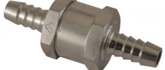
Bosch injection pump check valve for KAMAZ
KAMAZ EURO-2 stalls while driving
Check valve for injection pump BOSCH VE
Man tga. Repair. Injection pump check valve.
How to Test a Fuel Check Valve
Checking a faulty and serviceable Bosch VP30 injection pump valve on the engine and on the stand
KamAZ injection pump drive Part 2.
Injection pump return valve Euro 2 VG2600080213
modification of the Mitsubishi Pajero injection pump return valve (Mitsubishi Pajero), with a 4m40 engine for Kamaz
- Locker for KAMAZ 4308
- Body parameters of KAMAZ 53212
- Convert KAMAZ gearbox to MAZ
- KAMAZ lift hydraulic cylinder
- How to remove the rev limiter on a KAMAZ
- KAMAZ in the mud is cool
- KAMAZ odometer winder
- How to align brake pads on a KAMAZ video
- Electrical diagram of KAMAZ 65117 with cummins engine
- Remove the boiler from KAMAZ
- Lubrication of KAMAZ chassis
- Stocking air filter KAMAZ
- Bearing 306 KAMAZ
- KAMAZ accident at a crossing
- Specification KAMAZ 55102
The KAMAZ 740 engine does not develop full power
- Replace the air filter;
- Adjust the fuel supply angle;
- Clean the injectors, adjust the injectors;
- Repair the injection pump;
- Check the operation of the KAMAZ injection pump.
Uneven operation of the KAMAZ 740, KAMAZ 4310 can be caused by loss of functionality of individual injectors, a malfunction of the high-pressure fuel pump or its regulator. Damaged injectors must be replaced, and the injection pump, as a more expensive part, is checked on a fuel stand and repaired if necessary.
How to check the system for air leaks
There are two outlets on the KAMAZ fuel tank: fuel supply and return. So, you need to connect the air pumping hose from the receiver to the fuel supply and apply compressed air pressure to the low pressure fuel system, and turn off the return line. All connections, hoses, bolts with washers, they will show at the pressure where the air is leaking, fuel will flow from there. We eliminate all these shortcomings so that the system is airtight.
Kamaz tank intake
Check valve for Bosch KAMAZ fuel pump
KAMAZ EURO-2 stalls while driving
Check valve for injection pump BOSCH VE
How to Test a Fuel Check Valve
Man tga. Repair. Injection pump check valve.
The procedure for connecting tubes to the injection pump
Checking injectors and check valve.
Checking a faulty and serviceable Bosch VP30 injection pump valve on the engine and on the stand
Injection pump pumping 100% RESULT
- Wiring diagram KAMAZ 54115 color
- Installation of seats on KAMAZ
- KAMAZ hit by two trains
- Double-disc clutch of a KAMAZ vehicle
- Features of operation of KAMAZ 53501
- ABS device of a KAMAZ vehicle
- Shock absorption group for KAMAZ
- Is it possible to install a turbine on a simple KAMAZ?
- KAMAZ canvas canopy
- KAMAZ piston cylinders
- Oil pump KAMAZ 6520 characteristics
- KAMAZ engine overhaul
- Oil in the KAMAZ brake system
- Drives oil out of the KAMAZ tank
- Remake KAMAZ muffler
Injection pump repair
Troubleshooting methods for a high-pressure fuel pump depend on the type of device, as well as the cause of the breakdown. We list the most common repair measures.
Replacing the plunger pair with your own hands
Before performing an independent check (without using a special stand), you must have handyman tools and a new plunger pair on hand, as well as have experience in performing repair work. We will describe the description of checking the condition of the high-pressure fuel pump using the example of a common Bosch injection pump.
It is necessary to understand that dismantling the pump depends on the specific model and even the car engine, so the procedure will be described in general terms. So, to replace a plunger pair (the most common type of repair) you need to:
- remove the terminals from the car battery;
- disconnect all wires and hoses suitable for it from the high-pressure pump;
- dismantle parts that prevent its removal from the car;
- unscrew the fasteners and dismantle the pump;
- carefully disassemble the pump, it is important not to lose small parts, and also remember the disassembly sequence (you can photograph this process step by step on your phone);
- unscrew and remove the plunger from the pump;
- clean all pump parts from dirt (you can use special carb cleaners or similar cleaners for this);
- check the rollers, bearings and racks on the pump; they should not show significant wear;
- remove the valves and the so-called “silencer” from the old plunger pair, and then install them on the new pair;
- Carry out installation work in reverse order.
Installation of injection pump, injectors, high and low pressure pipes D-245
The injection pump mating plate must be clean;
nicks and other damage to the slab are not allowed. The fuel pump gasket must not show any visible damage.
When installing the fuel pump, you must align the marks of the fuel pump drive gear and the splined flange.
The splined flange of the fuel pump gear must fit freely, without jamming, onto the splines of the fuel pump shaft bushing.
The fuel pump gear flange mounting bolts must be tightened to a torque of 18…25 Nm.
When installing the fuel pump, be sure to check the fuel injection advance angle. This is done in the following sequence:
- set the regulator control lever to the position corresponding to the maximum fuel supply.
- Disconnect the high-pressure tube from the fitting of the first section and connect the momentoscope instead (Fig. 1).
- Turn the diesel crankshaft clockwise with a wrench until fuel free of air bubbles appears from the glass tube of the momentoscope.
- remove some of the fuel from the glass tube by shaking it.
- Turn the crankshaft counterclockwise 30...40°.
- Slowly rotating the diesel crankshaft clockwise, monitor the fuel level in the tube; at the moment the fuel begins to rise, stop rotating the crankshaft.
- remove the hatch cover;
- Unscrew bolts 1, 2 and 3 (Fig. 3) and loosen bolt 3 by ½…1 turn (do not unscrew the bolt);
- align the locking rod 2 (see Fig. 2) with the hole in the flywheel, turning the diesel crankshaft in one direction or the other; Using a wrench, turn the fuel pump shaft and splined flange by the nut until the fuel begins to rise in glass tube 1 (see Fig. 1) of the momentoscope;
- install bolts 1,2 and 3 (see Fig. 3) into matching holes, trying to position them as evenly as possible around the circumference;
5. tighten bolt 3 first, then bolts 1 and 2;
- Reinstall the high-pressure tube and remove the locking rod from the hole in the flywheel;
- Replace the hatch cover.
The alignment of the splines of the fuel pump bushing and the splined flange when installed on a diesel engine is ensured by turning the diesel crankshaft or the pump camshaft. Diesel engines must be equipped with injectors of the same group.
The sealing gaskets on the side adjacent to the injectors must be lubricated with solid oil US-1 GOST 33-51.
The injector mounting bolts must be tightened to a torque of 20…25 Nm.
High pressure pipes must be secured at a distance of 10...15 mm from the union nuts with clamps with gaskets.
Low pressure fuel pipes should be purged with compressed air before installation on a diesel engine.