Winch ZIL
On off-road trucks (ZIL-157, KrAZ-214, Ural-375, etc.) a winch is installed. with the help of which difficult road sections are overcome. evacuate stuck cars, lift and tighten loads.
Winch ZIL
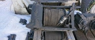
The winch is a drum on which a cable is wound. The drum is mounted on a shaft with a worm wheel that is engaged with the worm. The worm pair is located in the crankcase and is driven from the power take-off using a cardan transmission. The power take-off usually has two working gears for pulling the load and one for unwinding the cable.
Most winches are equipped with an automatic band brake. When the winch drum suddenly rotates under load in the opposite direction, i.e. When the car's clutch is disengaged, the brake band tightens and creates significant resistance to the rotation of the brake drum. The stopping of the drum is facilitated by the self-braking action of the worm pair of the winch.
Winch disassembled
The winches of GAZ-66 vehicles develop a traction force of 3500 kg, ZIL-4500-5000 kg, Ural-375 - 7000 kg, KrAZ-214B-8000 kg. The working length of the winch cable is 55-65 m.
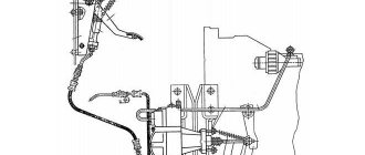
Power take-off
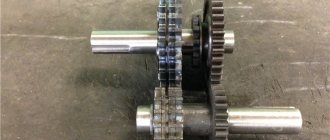
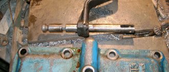
Installed on the gearbox, there is a hatch on the right side for installation. PTO with reverse, turns in both directions. The PTO consists of a gearbox housing, a gear block, a main shaft, a gear axis, a shift fork, 2 ball bearings, and a flange. The PTO gear rotates from the rear speed of the gearbox. When installing the PTO, the shafts should rotate freely without snagging the gears, turning them by hand. The shaft is adjusted by a set of paper shims under the bearing cap. The maintenance of the PTO gearbox is the same as that of the gearbox.
power take-off box
Maintenance and repair
Maintenance and repair of the ZIL-131 should only be carried out with the engine turned off and at a special site.
Reasons why repair work is required:
- The engine gets very hot and the muffler fires.
- Resource exhaustion, which causes the crankshaft, cylinder block, transmission and other main components of the car to fail.
- Burnout of the piston device.
- The presence of damage and cracks on the engine housing, gearbox and cylinder block.
- Short circuit or open circuit.
Maintenance involves replacing the oil fluid, external inspection of units and replacing consumables.
Why it won't start and what to do
The power unit may not start due to a lack of fuel in the system, a stuck air throttle valve, or clogged jets.
In order to repair the engine, you must:
- Blow out the fuel lines.
- Check the functionality of the needle valve located on the carburetor.
- Inspect the fuel pump for defects and damage.
- Blow out cylindrical elements.
- Crank the engine using an electric starter with the throttle valves fully open.
- Check the operation of the air damper.
- Wash the jets with acetone and blow through with air.
Carburetor adjustment
With a properly adjusted carburetor, the throttles and choke valves will open and close in response to the position of the brake pedal.
Carburetor adjustment takes place in several stages. First, the manual and foot drive of the throttles are adjusted, only after that they move on to setting the air damper.
The foot-type drive is adjusted using a threaded fork, and the manual drive is adjusted using a clamp that is installed on the end of the drive cable.
At low engine idle speeds, vacuum from the intake manifold is transmitted through the opening of the idle system, after which the working fluid enters the lubrication system.
How to set the ignition
In order to set the ignition on a ZIL, you must perform the following steps:
- Set the piston mechanism of cylinder number 1 to the top dead center position.
- Rotate the crankshaft until the hole on the crankshaft pulley aligns with the top dead center mark.
- Position the groove on the distributor drive shaft.
- Insert the drive into the slot of the block.
- Rotate the crankshaft to the installation angle.
- Remove the mounting bolt from the plate.
- Turn on the ignition.
- Rotate the switchgear housing into the drive socket.
- Check that the wires on all cylinders are installed correctly.
Clutch adjustment
Clutch adjustment is carried out in several stages. The first step is to adjust the free play of the clutch pedal. To do this you need:
- Measure the stroke from the center of the plate to the mechanism.
- Lower the pedal all the way.
- Connect the lever to the top eye of the pusher using an eccentric pin.
- Tighten the castle nut.
At the second stage, it is necessary to debug the clutch stroke. Its free play should not exceed 4 mm. Adjustment is carried out using a spherical nut.
At the last stage, you need to adjust the full stroke of the hydraulic power steering pusher.
Winch block (polyplast)
Each car with a winch is equipped with a polyplast block. Using this block you can double the power of the winch, since it divides the force in half. When operating a vehicle, the winch cable must always be tightly wound around the drum.
The winch is engaged in the same way as the gearbox. Depress the clutch and engage the PTO in the desired direction and release the clutch. In some cases, it is possible to unwind the cable while the vehicle is moving.
polyplast block
Important when operating the winch
- Do not pull the cable to the very end; the remainder of the cable should be 4 turns of the drum. The working length of the cable is 65 m and the total length is 70 m.
- The oil temperature in the crankcase should not exceed 130 degrees.
- The cable tension should not be more than 45 kN. In other cases, use a pulley block.
- Turn on the PTO transfer case and use your hands to pull the cable tight.
winch diagram zil
Prohibited when using
- It is prohibited to engage reverse gear when the winch is operating.
- When the winch load is heavy, speed gears cannot be engaged.
- Do not tow another vehicle with a winch.
- When the winch is operating, it is prohibited to stand near the cable or align the cable in the winch drum.
- If the winch overheats in the gearbox gears, it is necessary to stop work and find the cause of the overheating.
worm gear
Spare parts for Ural, Kraz, MAZ, Kamaz trucks. Engine parts YaMZ-236, YaMZ-238
__________________________________________________________________________
__________________________________________________________________________
Winch ZIL-131
___________________________________________________________________________
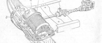
A winch is installed on the ZIL-131 vehicle, intended for self-pulling the vehicle when overcoming difficult sections of the road, as well as for providing assistance to other vehicles stuck along the way. The winch (Fig. 91) is installed at the front of the car, bolted to the front buffer and to the front frame cross member. The front buffer is bolted to special removable side member extensions.
The winch is driven by a cardan shaft from a power take-off mounted on the gearbox. The gear ratio of the winch gearbox is 31. The maximum traction force of the winch is 50 kN (5000 kgf). Under heavy loads, the safety pin installed in the front fork and the end of the propeller shaft is cut off and protects the winch cable from breaking. The total length of the winch is 72 m. The working length of the cable is 65 m. Drum 12 of the winch rotates freely on the shaft. To prevent oil leakage from the gearbox, a cover with an oil seal is installed on the drum shaft between the winch gearbox 11 and drum 12.
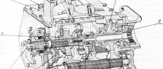
Fig.91. Car winch ZIL-131 The drum is connected to the shaft using a sliding coupling 3, which has end cams. The drum engagement clutch moves on the shaft on two keys. When the coupling moves, its end cams engage with the drum end cams and rotate with it as one unit. Fork 4 for drum activation is installed on the winch traverse. The power fork is equipped with a brake shoe, hingedly mounted in the traverse ears on the axis. When the clutch is disengaged, the brake shoe, under the action of a pressure bolt with a spring, rests against the end of the drum flange, slows down its rotation and prevents the cable from unwinding itself when unwinding manually. The brake is adjusted by tensioning or loosening the spring of the thrust bolt using a nut with a lock nut, and if necessary (when the spring force is not enough) by moving this bolt by screwing in or unscrewing the threaded bushing. The spring pressure is adjusted correctly if the cable unwinds under hand force without unwinding. There is a depression in the drum flange into which the end of the cable is placed and secured with a bracket. The ZIL-131 winch cable is steel, non-unwinding, with a metal core. At the free end of the cable there is a hook connected to the cable through a thimble. The drum shaft rotates on three bronze bearings, two of which are installed in the gearbox housing and one in the traverse. The cross member and gearbox housing are bolted to the cross members. The drum shaft bearing is lubricated through oiler 1 placed in the traverse, and the drum rotation surface on the shaft is lubricated through two oilers 13 located at the ends of the drum. The drum shaft bearings installed in the gearbox housing are lubricated by oil flowing from the gearbox worm wheel and from the walls of the crankcase cover. The winch gearbox (Fig. 92) consists of a globoidal single-throw steel worm, a worm wheel with a bronze rim, a split housing, a drum shaft, an automatic brake, bearings and their covers. The worm wheel 3 of the gearbox is installed on the shaft 7 of the winch drum on two keys and secured against axial movements with a pin. The movement of the drum shaft with the worm wheel in the axial direction is carried out by changing the thickness of the set of gaskets under the washer 4 installed between the right end of the gearbox housing and the end of the recess in the cover 6. The washer 4 is attached to the end of the shaft with bolts. The upper half of the gearbox housing has an inspection hatch closed by a cover 13. The worm 25 is installed in the gearbox housing 15 on two tapered roller bearings. The bearings are closed with covers 16 and 26. A cuff 21 is pressed into the cover 16. The bearing covers are attached to the gearbox housing with bolts. Fig.92. Winch gearbox ZIL-131 At the rear end of the worm shaft there is a drum 17 for the automatic brake of the winch gearbox and a flange 18 for fastening the propeller shaft. The brake drum is mounted on a key, and the flange is on splines, and they are secured against axial movements with a nut.
The brake drum is covered with a cover. A felt cuff 19 is installed in the cover, preventing dirt from getting into the brake. An O-ring 23 made of copper or paronite is installed between the end of the inner ring of the bearing and the end of the brake drum hub. The drum is braked by brake band 9 with a friction lining. One end of the brake band is rigidly fixed in the wall of the bearing cover, and the other is movable in the hole of the cover using a spring, which tightens the band in the direction opposite to the rotation of the worm shaft when winding the winch cable. The tape, under the influence of friction, compresses the spring, which leads to a weakening of the pressure of the tape on the drum, i.e., to a decrease in braking. Due to the rigid fastening of the opposite end of the tape during reverse rotation under the influence of friction, the tape self-tightens, causing the worm to slow down. At a low rotation speed of the worm shaft, the braking force created by the automatic brake is insignificant and does not prevent the cable from unwinding. In the event of shearing as a result of overload of the safety pin, when the winch drum begins to rotate in the opposite direction at an increased speed, the braking effect becomes significant and serves as an addition to the self-braking action of the worm gear, which prevents rapid rotation of the winch drum and unwinding of the cable. The brake band tension is adjusted by nut 11. When the nut is rotated clockwise, the spring pressure increases. The brake must be adjusted so that when the cable is unwinding, the brake drum does not heat up excessively. The winch cable guides are bolted to the lower flanges of the front buffer and the rear cross member of the ZIL-131 winch. At the front, between the guides, there is a guide roller for the winch cable and a rod that keeps the cable from falling out. The roller rotates on an axis secured with nuts in the guides. Lubricate the roller bearings through an oiler installed at the left end of the roller axis. The cardan shaft is tubular and has two hinges. The front fork is mounted on the cylindrical end of the shaft and secured with a safety ring. The rear fork (sliding) is mounted on the splined end of the shaft. The universal joint crosspieces are installed in the forks on needle bearings. The bearings are held in the fork holes by snap rings. The winch block (pulley block), which is used if it is necessary to increase the traction force of the winch or change the direction of traction, and the cable for attaching the winch block are included in the accessory kit of each vehicle equipped with a winch. When the vehicle is moving, the winch cable must be completely tightly wound around the drum, and the winch drum must be engaged (connected to the shaft with a coupling). Disconnecting the drum from the shaft is only allowed when manually unwinding the cable. To turn on the winch, you must press the clutch pedal all the way, engage the desired gear in the power take-off and release the clutch pedal. Unwind the free cable manually, without engaging the gear, but turning off the drum clutch. In some cases, you can engage the gear to unwind the cable. To self-extract a ZIL-131 vehicle, you need to unwind the cable, hook it to some reliable object (tree, stump, pole, etc.), engage the gear for winding the cable in the power take-off box and pull it out at a speed of rotation of the winch drum shaft of 14 -16 rpm When self-pulling on wet turf roads, it is allowed to engage the drive axles in first gear of the gearbox. When winching another vehicle, place the gearshift lever in neutral and brake the vehicle. After pulling is complete, stop the winch by disengaging the clutch and place the power take-off lever in the neutral position. To loosen the cable, you need to put the power take-off lever in the position corresponding to the unwinding of the cable. To secure the winch cable to the riding position, you need to hook the winch cable hook to the rear tow hook, engage the power take-off gear to reel in the cable, and smoothly pull it. After this, you need to put the power take-off lever in the neutral position. If a block is used to increase the traction force during self-pulling, the block must be secured to an object selected as a support, and the winch cable hook to one of the front towing hooks of the vehicle. If the block is used to change the direction of the traction force when pulling out another machine, it is fixed on an object that serves as a support, and the hook of the cable is hooked onto the towing hook of the machine being pulled out. If a block is used to increase the traction force when pulling out another machine, it is secured to the hook of the machine being pulled out, and the hook of the cable to an object that serves as a support using a cable for securing the block.
_________________________________________________________________________
_________________________________________________________________________
_________________________________________________________________________
- Cardan shafts and power take-off Ural-4320
- Transmission gearbox Ural-4320
- Bridges Ural-4320
- Transfer case Ural-4320
- Steering Ural-4320
- Truck cranes and cranes based on trucks
_________________________________________________________________________
_________________________________________________________________________
- Cylinder block and cylinder head YaMZ-236 HE2, YaMZ-236 BE2
- Checking and adjusting YaMZ-236
- Power system and lubrication system YaMZ-236
- Driven and driven clutch discs YaMZ-236, 238
- Cooling and lubrication systems YaMZ-238
- Fuel injection pump YaMZ-238
_________________________________________________________________________
- Kamaz diesel engine
- Repair and adjustment of Kamaz power steering
- Kamaz-152 gearbox with divider
- Gearbox parts for Kamaz-5320 gearbox
- Kamaz transfer case and driveshafts
- Kamaz gearbox repair
- Clutch KamAZ-5320
- Construction of Kamaz-4310 drive axles
- Power steering MAZ-5551, 5549, 5335, 5336, 5337
- Front axle and steering rods MAZ-5551, 5549, 5335, 5336, 5337
- Clutch adjustment MAZ-5551, 5549, 5335, 5336, 5337
- Adjustment and repair of gearboxes MAZ-5551, 5549, 5335, 5336, 5337
- Repair and maintenance of the rear axle MAZ-5551, 5549, 5335, 5336, 5337
- Front axle parts and steering rods MAZ-5516, 5440
- Steering Maz-5516, 5440
- Details of driving axles Maz-5516, 5440
- Clutch device ZIL-130
- Repair of ZIL-130 gearbox
- Repair of rear axle ZIL-130
- Basic parts of the ZIL-130 engine
- Transfer case and power take-off ZIL-131
- Drive axles ZIL-131
- Steering ZIL-131
- Maintenance of ZIL-645 engine parts
How to silence Zil?
How to turn off the engine zil bull
- Disengage the clutch.
- Place the gear shift lever in neutral position.
- Engage the clutch, sharply press the fuel control pedal and immediately release it, thereby increasing the engine speed.
Interesting materials:
Is it possible to take Ergoferon after meals? Can Omez be taken after meals? Is it possible to sit in a cafe with your own food? Can dry cat food be mixed with regular food? Is it possible to create a new Apple ID if I have an old one? Is it possible to find out whether a person has you on Viber or not? Is it possible to bring your own food to KFS? Is it possible to go to New Holland with your own food? Is it possible to eat dumplings while on a diet? Is it possible to get pregnant if you have problems with the thyroid gland?
Installation of winch - ZIL-131:
131-4206011 131-4501010-B 201496-P8 304910-P 1 2 2 3 4 5 6 7 8 9 10 11 12 13 14 15 16 17 18 19 20 20 21 22 23 24 25 26 27 2 8 29 30 31 32 33 34 35 36 37 38
List of components for Installing a winch on ZIL-131
Parts diagrams are for reference purposes only! We do not sell all spare parts for installing a winch on the ZIL-131 presented in this list. If there is a “Show prices” link in the right column, these parts from “Winch Installation” are on sale. Availability in warehouses for details and prices, see the product card. If there is no “Show cost” link in the right column, we do not sell such parts and do not accept orders for them.
| № | Part code | Name | Part Information | Show all prices |