Device
The device of this vehicle includes such elements as:
- Power unit. It has a gasoline engine equipped with a carburetor and two falling flow chambers. Inside the motor there is a pump element and an economizer, as well as a mechanism for forced idle. The unit is made in accordance with the international environmental standard Euro-0.
- Brake system.
- Electrical equipment, including sound and light alarms, headlights, low and high beams.
- A pneumatic system that makes the car ride smoother.
- Transmission. A manual transmission is installed here. Gear shifting is carried out using a special control lever.
- Clutch mechanism, wheels and tires.
- Front and rear driving axle.
Brake system
There are 2 independent braking systems installed here: one acts on all wheel mechanisms, and the second only on the transmission. The brake system of the ZIL-130 modification was taken as a sample.
The brakes, equipped with a pneumatic drive, are equipped with an air compressor, as well as pistons, a two-cylinder cooling system for the working fluid. Such braking devices are located on the right side of the body inside the car and are driven by a belt-type transmission, which is supplied from the pulley of the water pump element.
All cylindrical mechanisms of the system are made of cast iron and mounted on the crankcase. The piston part is connected to the upper head of the connecting rod using a floating pin.
When the brake pedal is released, the access of the compressed air flow to the chambers is stopped, due to which the vehicle continues to move.
Electrical equipment
The type of system of electrical devices and mechanisms of this vehicle is single-wire. The negatively charged terminals of the current sources are connected to the ground of the ZIL. The rated voltage in the system is 12 V. Low voltage wires of the PGVA type and high voltage wires of the PVV type are used inside the mechanism.
In order to check the serviceability of the insulating coating of the electrical circuit, it is necessary to conduct an external inspection of the electrical equipment. If an open circuit is detected, it is recommended to insulate the exposed low pressure wire with special tape. If the high voltage wire fails, it is necessary to replace it with a new one in accordance with the electrical diagram given in the vehicle repair manual. High voltage wires cannot be repaired.
Pneumatic system
The ZIL pneumatic system includes the following elements:
- compressor with plugs;
- tube leading from the windshield wiper;
- brake chamber;
- tee tube;
- union;
- tap elbow;
- dispensing type crosspiece;
- mounting bracket;
- pressure level regulator in the system;
- bracket;
- hoses;
- clamp;
- safety valve.
Before driving, it is recommended to measure the pressure level in the pneumatic system. It must be at least 4.5 kg/cm². If the indicator exceeds 7.4 kg/cm², it means the pressure regulator or unloading device is damaged.
When you press the brake pedal sharply, the pressure in the cylinders should decrease, and in the brake chambers it should become equal to the pressure in the cylinder. If this does not happen, it is recommended to disassemble the mechanism and conduct an external inspection of the parts for wear.
Disassembly and assembly of a combined brake valve.
To disassemble the tap, unscrew the cover together with cover 2 (see Fig. 12-22) and disconnect the tap drive rod 1 from lever 3, then remove the cover. To remove the lever housing, unscrew the bolts securing the lever housing to the valve body 8. If necessary, remove the roller with cam 25 and the axle with small lever 29 from the lever body by pressing it out of the lever body.
To remove the large lever 3 from the rod 7, it is necessary to press out its axis and remove it together with the rod 1.
brake valve
Fig. 12-22. Combined brake valve with single-circuit brake actuator:
1 — brake valve drive rod; 2 — protective cover; 3 - large lever; 4 — stop of the large lever; 5 — spring of the equalizing section that controls the trailer brakes; 6 — rod guide bushing; 7 — rod; 8 — body; 9 - membrane; 10 and 17 — exhaust valve seats; 11 O-ring; 12 and 18 — exhaust valves; 13 — adjusting shims; 14 and 19 — intake valves; 15 — intake valve seat; 16 - cover; 18 - cover; 20 – membrane of the brake signal switch; 21 — contact connecting plate; 22 — contact spring; 23 - clamps of the brake signal switch; 24 - moving contact; 25 — switch body; 26 — channel for supplying compressed air to the brake signal switch membrane; 27 — balancing spring of the section that controls the trailer brakes; 28 — balancing spring cup; 29 — small lever; 30 - lock nut; 31 — rod stroke limiter; 32 — shaft of the manual drive lever; 33 — lever connected to the parking brake drive; 34 — stop of the manual drive lever. The arrows indicate the direction of air movement: A - in the line of the trailer; B - to the brake chambers of the tractor; C - from an air cylinder; D - into the environment.
Specifications
Technical characteristics of ZIL-4331:
| Maximum load capacity | 6000 kg |
| Engine displacement | 6 l |
| Diameter of cylindrical elements | 100 mm |
| Piston stroke | 95 mm |
| Power unit power | 150 hp |
| Number of crankshaft revolutions | 3200 per minute |
| Compression ratio | 7,1 |
| Gearbox ratio | 6,45 |
| Maximum torque | 402 Nm |
| Wheelbase | 5000 mm |
| Fuel tank volume | 170 l |
| Cooling system capacity | 27 l |
| Ground clearance distance | 330 mm |
| Tire size | 9.00R20 |
| Engine weight | 93 kg |
| Overall dimensions of transport | 6370*2422*2810 mm |
| Average fuel consumption of ZIL-4331 per 100 km | 36 l |
Description of the truck engine: it is equipped with 6 cylinders and 2 valves, the type of fuel used is diesel. Engine model: YaMZ-236.
Weight parameters:
- curb weight - 11700 kg;
- transport weight - 4820 kg.
Modifications
There are several modifications of ZIL-4331:
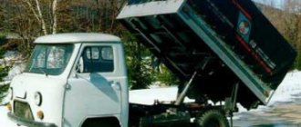
- dump truck;
- tractor;
- onboard;
- with a manipulator;
- firefighter.
Dump truck
The dump truck is equipped with a ZIL-645 engine and a lowered compressor, which is lowered under the hood. This type of transport has a high level of maneuverability, so it can be used even in off-road conditions.
Performance characteristics of this modification:
| Dimensions | Length - 6370 mm Width - 2500 mm Length - 2655 mm |
| Track | Front wheels - 1930 mm Rear wheels - 1850 mm |
| Clearance | 330 mm |
| Full mass | 4820 kg |
| Maximum lifting weight | 6000 kg |
| Fuel tank volume | 165 l |
| Engine power | 185 horsepower |
| Maximum torque | 377 Nm |
| Maximum transport speed | 95 km/h |
| Transmission | Mechanical, 9 steps |
| Engine displacement | 8.74 l |
| Number of cylinders | 8 |
| Number of valves | 16 |
| Average diesel consumption | 30 l per 100 km |
| International environmental standard | Euro 2 |
| Number of seats in the cabin | 3 |
| Wheel formula | 4*4 |
Tractor
The ZIL-442100 truck tractor is used for transporting various cargoes on any type of road surface. A ZIL-645 diesel engine is installed here.
Technical indicators and model parameters:
| Total number of wheels | 4 |
| Number of driving wheels | 2 |
| Curb weight | 5025 kg |
| Pressure exerted on the front axle | 29250 kgf |
| Rear Cart Load | 21000 kgf |
| Load on the fifth wheel coupling | 6200 kgf |
| Full mass | 11450 kg |
| Road train | 23500 kg |
| Permissible towbar weight | 18175 kg |
| External turning radius | 6900 mm |
| Highest speed | 85 km/h |
| Average diesel fuel consumption per 100 km | 24.4 l |
| Fuel tank volume | 170 l |
| Number of cylindrical parts | 8 |
| Compression ratio | 18,5 |
| Power | 185 hp |
| Torque | 510 Nm |
Onboard
The ZIL-433180 onboard vehicle is used as part of a road train for transporting various types of cargo. This model is distinguished by a non-standard hood mask and radiator lining made of plastic.
The power unit has 8 cylinders, which are arranged in a V-shape. The motor is equipped with a liquid cooling system.
Technical indicators and modification characteristics:
| Wheel formula of the car | 4*2 |
| Maximum weight of transported cargo | 8000 kg |
| Curb weight | 6200 kg |
| Front wheel load | 3170 kgf |
| Rear axle load | 3030 kgf |
| Total weight | 14500 kg |
| Road train | 26000 kg |
| Overall dimensions of the cargo platform | Length - 4692 mm Width - 2326 mm Height - 575 mm |
| External turning radius | 8000 mm |
| Speed | Up to 90 km/h |
| Fuel tank volume | 170 l |
| Engine displacement | 7.12 l |
| Compression ratio | 17 |
| Power unit power | 178 hp |
| Torque | 708 Nm |
| Engine speed | 3200 rpm |
| Driven disk diameter | 380 mm |
With manipulator
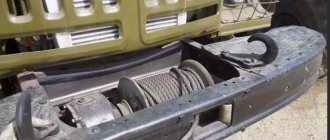
ZIL with a manipulator is used for lifting loads, as well as for performing installation work. The crane installation is equipped with a front-type winch. The maximum weight of the load lifted by the installation is 3500 kg.
Technical data:
| Maximum load capacity | 3500 kg |
| Engine displacement | 17 l |
| Diameter of cylindrical elements | 114 mm |
| Piston stroke | 113 mm |
| Power unit power | 175 hp |
| Number of crankshaft revolutions | 3200 per minute |
| Compression ratio | 16,5 |
| Gearbox ratio | 7 |
| Maximum torque | 702 Nm |
| Wheelbase | 3350 mm |
| Fuel tank volume | 170 l |
| Cooling system capacity | 50 l |
| Ground clearance distance | 330 mm |
| Tire size | 9.00R20 |
| Engine weight | 85 kg |
| Overall dimensions of transport | 7040*2500*2480 mm |
| Average fuel consumption | 37 l |
Firefighter
The fire truck is equipped with an AC-3.2-40 tank. The volume of the water tank of this equipment is 3200 l, and the foam tank is 200 l. At a system pressure of 10 bar, the hose capacity is 3000 l per minute. The jet supply range is 70 m.
Transport parameters and indicators:
| Total number of wheels | 4 |
| Number of driving wheels | 2 |
| Curb weight | 5525 kg |
| Pressure exerted on the front axle | 29250 kgf |
| Rear Cart Load | 21000 kgf |
| Load on the fifth wheel coupling | 6200 kgf |
| Full mass | 13450 kg |
| Ground clearance | 265 mm |
| External turning radius | 6900 mm |
| Highest speed | 90 km/h |
| Average diesel fuel consumption per 100 km | 34.4 l |
| Fuel tank volume | 260 l |
| Number of cylindrical parts | 8 |
| Compression ratio | 18,5 |
| Power | 245 hp |
| Torque | 710 Nm |
Spare parts for Ural, Kraz, MAZ, Kamaz trucks. Engine parts YaMZ-236, YaMZ-238
__________________________________________________________________________
__________________________________________________________________________
Brakes and steering of ZIL-4331 cars
___________________________________________________________________________
Pneumatic drive of brakes of a ZIL-4331 car. The pneumatic drives of brake systems with multi-circuit drives of cars ZIL-4331, 433360, 431410, etc.) have a lot in common in the purposes and design of autonomous circuits, in the pneumatic drive and the devices used.
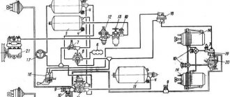
Rice. 2. Diagram of the pneumatic drive of the brake systems of the ZIL-4331 car 1 - compressor; 2 — brake chambers of the front wheels; 3—control valves; 4 — pressure limitation valve; 5 — pneumoelectric sensors for turning on the brake signal; 6 — auxiliary brake system valve; 7 — air distributor; 8 — emergency parking system release valve; 9, 11 — air cylinders of the service brake system; 10 — condensation air cylinder; 12 — taps for draining condensate; 13 — pneumoelectric sensors for pressure drop in brake systems; 14 - triple safety valve; 15 — parking brake valve; 16 — pneumatic cylinders for driving the auxiliary brake system mechanisms; 17 — two-pointer pressure gauge of the service brake system; 18 — two-section valve of the service brake system; 19 — double safety valve; 20 — pressure regulator; 21 — fuse against condensate freezing; 22 — air cylinder of the parking brake system with a sensor for its activation; 23 — air cylinder of the auxiliary brake system; 24 — control valve for the brake system of a trailer (semi-trailer) with a single-wire drive; 25 — control valve for the brake system of a trailer (semi-trailer) with a two-wire drive; 26—single safety valve; 27— accelerator valve; 28 — brake chambers of the rear wheels; 29 — quick release valve; 30 — brake force regulator; 31 — two-line bypass valves; 32, 33 - connecting heads The diagram of the pneumatic drive of the brakes of the ZIL-4331 car is shown in Fig. 2. Compressed air from compressor 1 through the pressure regulator 20, the condensate freeze guard 21, the condensation air cylinder 10 is supplied to the block of protective valves (double 19 and triple 14), which distribute the air, filling the air cylinders of the first four independent circuits: - brake drive front wheels (contour /); — rear wheel brake drive (circuit //); drive of the parking and spare brake systems, as well as the combined drive of the brakes of a trailer or semi-trailer (circuit ///); — auxiliary brake drive and power supply to other pneumatic devices, including vehicle transmission units (circuit IV). Along with this, there is a V drive circuit for the emergency brake release system, which does not have its own air cylinder.
All air cylinders have valves 12 for draining condensate, and all circuits have built-in pneumatic-electric sensors 13 for compressed air pressure drop. A two-pointer pressure gauge 17 is connected to the air cylinders of the two first circuits of the drive mechanisms of the ZIL-4331 service brake system. To check the operation of the brake systems, valves 3 control outlets are installed at various points of the pneumatic drive, to which portable pressure gauges are connected. Circuit I includes an air cylinder 11, a pressure drop sensor 13, a lower section of the brake valve 18, a pressure limiting valve 4, brake chambers 2 of the front wheels and a control valve 3. Circuit II includes an air cylinder 9, a pressure drop sensor 13, an upper section of a valve 18, a brake force regulator 30 with an elastic element, a control valve 3 and brake chambers 28 of the ZIL-4331 rear wheels. Circuit III includes an air cylinder 22, a pressure drop sensor 13, a manually operated parking brake valve 15, an accelerator valve 27, two dual-line bypass valves 31, a quick brake release valve 29, a control valve 3, spring energy accumulators located in the brake chambers 28 rear wheels. This circuit also includes: a single safety valve 26, trailer (semi-trailer) brake control valves 25 and 24, respectively, with a two-wire and a single-wire drive, two automatic connection heads 32, one connection head 33 (type A) and a brake signal sensor 5 that provides light signal when any ZIL-4331 brake system is operating. Circuit IV includes an air cylinder 23, a pressure drop sensor 13, a push-button valve 6 for turning on the auxiliary brake, two pneumatic cylinders 16, a brake signal sensor 5, a control valve 3 and an air distribution box 7, which is designed to supply compressed air to the clutch pneumatic booster, switch gears in the divider, pneumatic windshield wipers and other consumers of compressed air. Circuit V includes a push-button pneumatic valve 8 for emergency release of the parking brake, a dual-line bypass valve 31, a triple safety valve 14 and brake chamber energy accumulators 28. Steering control of ZIL-4331 vehicles The main condition for trouble-free and durable operation of the ZIL-4331 steering control is keeping it clean hydraulic system.
For power steering, only clean filtered oil is used, which is poured through a funnel with a double mesh and a filler filter installed in the pump reservoir. The use of contaminated oil causes rapid wear of the pump and hydraulic booster. The power steering system is filled at the manufacturer with all-season oil for hydraulic systems of R-brand vehicles (TU 38-1011792-71). This oil has a low pour point and contains anti-wear, antioxidant and other additives that improve its quality. When operating the ZIL-4331 power steering system filled with oil P, it is only added to the pump reservoir if necessary. An oil change is performed only when repairing power steering system units. In the absence of oil P, it is permissible to add oils recommended by the manufacturer as substitutes. However, the durability of the pump and steering mechanism is reduced. When adding substitute oil, the oil is changed 2 times a year (in autumn and spring). Rules for adding and changing oil, as well as brands of substitute oils, are given in the “Steering Maintenance” section. If the hydraulic booster fails due to damage to the ZIL-4331 power steering pump or the hydraulic booster itself, or destruction of the pump drive hose or belt, you can only use the steering mechanism for a short time, until the malfunction is eliminated. Long-term operation of a vehicle with inoperative power steering leads to rapid wear of the steering mechanism or its breakdown, since this overloads the thrust ball bearings, steering screw and other parts of the ball nut assembly. The wear of the driveshaft and steering column also accelerates. For the same reason, it is not allowed to tow a car for a long time with the engine not running without hanging its front axle. It is prohibited to stop the engine until the vehicle comes to a complete stop, and also to move with the engine not running on descents or coasting along a horizontal section of the road. In these cases, the ZIL-4331 power steering pump stops working and the force on the steering wheel and on the steering mechanism parts increases sharply. When maneuvering and getting out of deep ruts when driving on bad country roads, it is forbidden to hold the steering wheel turned all the way in one direction or another for a long time.
In this case, the pump operates on the safety valve, which causes rapid heating of the oil and can lead to pump failure. To continue driving in the event of failure of the power steering hoses of the ZIL-4331, connect the discharge hole of the pump to the return pipe on the pump reservoir, close the discharge and return holes of the steering mechanism with wooden plugs or in another way that provides protection against the ingress of dirt or foreign bodies, and add oil. With such movement, the engine must operate at the lowest possible crankshaft speed; monitor the temperature of the oil in the pump reservoir and if it gets too hot, stop the car so that the oil cools down.
_________________________________________________________________________
_________________________________________________________________________
_________________________________________________________________________
- Cardan shafts and power take-off Ural-4320
- Transmission gearbox Ural-4320
- Bridges Ural-4320
- Transfer case Ural-4320
- Steering Ural-4320
- Truck cranes and cranes based on trucks
_________________________________________________________________________
_________________________________________________________________________
- Cylinder block and cylinder head YaMZ-236 HE2, YaMZ-236 BE2
- Checking and adjusting YaMZ-236
- Power system and lubrication system YaMZ-236
- Driven and driven clutch discs YaMZ-236, 238
- Cooling and lubrication systems YaMZ-238
- Fuel injection pump YaMZ-238
_________________________________________________________________________
- Kamaz diesel engine
- Repair and adjustment of Kamaz power steering
- Kamaz-152 gearbox with divider
- Gearbox parts for Kamaz-5320 gearbox
- Kamaz transfer case and driveshafts
- Kamaz gearbox repair
- Clutch KamAZ-5320
- Construction of Kamaz-4310 drive axles
- Power steering MAZ-5551, 5549, 5335, 5336, 5337
- Front axle and steering rods MAZ-5551, 5549, 5335, 5336, 5337
- Clutch adjustment MAZ-5551, 5549, 5335, 5336, 5337
- Adjustment and repair of gearboxes MAZ-5551, 5549, 5335, 5336, 5337
- Repair and maintenance of the rear axle MAZ-5551, 5549, 5335, 5336, 5337
- Front axle parts and steering rods MAZ-5516, 5440
- Steering Maz-5516, 5440
- Details of driving axles Maz-5516, 5440
- Clutch device ZIL-130
- Repair of ZIL-130 gearbox
- Repair of rear axle ZIL-130
- Basic parts of the ZIL-130 engine
- Transfer case and power take-off ZIL-131
- Drive axles ZIL-131
- Steering ZIL-131
- Maintenance of ZIL-645 engine parts
Manual
The instruction manual includes several sections:
- General information about the car.
- Instructions on how to start a cold engine using an electric torch device.
- Basic rules that must be followed when starting and driving vehicles.
- The main malfunctions of the power unit and how to eliminate them.
- Recommendations for carrying out repair work.
- Possible breakdowns of the brake system.
- The process of assembling and installing a high pressure fuel pump.
- Assembly and installation of a diesel boost corrector.
- The structure of the main components of the car.
- Adjusting the clutch and replacing fine filters.
- Maintenance frequency.
- Rules for storing and transporting ZIL.
Checking and adjusting the combined brake valve.
Each repaired and assembled brake valve is tested on a pneumatic installation made according to the diagram shown in Fig. 12-24. The air pressure in tank 3 must be equal to 0.7 MPa (7.0 kgf/cm) and maintained for the entire test period. Air should be supplied to the inlet valves of the faucet.
brake valve drive
Fig. 12-23. Brake valve drive for vehicles with single-circuit drive:
1— thrust of the foot drive of the crane; 2- cover; 3- lever; 4 and 5 - adjusting screws; 6 - rod for manual drive of the trailer crane; 7 and 11 — locknuts; 8 and 12 forks; 9 and 13 - fingers; 10 - handbrake drive lever; 14- intermediate lever; 15 — pedal thrust; 16 — brake pedal; 17 – cabin floor; 18— tension spring
test scheme
Rice. 1 2-24. Diagram of the installation for testing a combined vehicle brake valve: 1 - brake valve under test; 2, 5 and 7 - pressure gauges; 3 - air tank with a capacity of 20...25 p; 4— pass-through valve; 6 and 8 - air tank with a capacity of 1 liter; 9 - three-way valves; 10 — control lamp; 11 - current source; 12 fuse 5 A; 1 – from the air source
Plug one hole each in the upper and lower covers of the brake valve, and connect the second to reservoirs 6 and 8, respectively. Supply an electric current of 12 V from the current source 11 to the brake signal switch, and turn on a test lamp [0 of such power, so that the power is 5A, and the fuses are 12. The brake valve and brake signal switch can be checked for leaks and operability on a pneumatic installation; the valve can also be adjusted.
In the brake valve, the free stroke of the lever 3 (see Fig. 12-22) of the valve, the free stroke of the lever 32 of the manual drive, the working stroke of the rod 7 of the trailer section, the stroke of the inlet valves 14 and 19 of the trailer and car sections, as well as the air pressure in trailer crane sections.
faucet adjustment
Rice. 1 2—25. Adjusting the valve stroke of the combined brake valve of the ZIL-431410 car with a single-circuit brake drive:
a - valve stroke; b - frozen method, valve stroke values
The free play of lever 3 (see Fig. 12-22) of the tap and lever 33 of the manual drive of the tap, which does not cause movement of the tap membrane, must be within 1...2 mm, which is determined by rocking the levers.
Adjust the free play of levers 3 and 33 using adjusting bolts 4 and 34 with the locknuts loosened, which must be tightened after adjustment.
The working stroke of the rod 7 of the crane section for a trailer should be 3... 5 mm. The rod stroke is adjusted with bolt 31 and secured with a lock nut.
The air pressure in the trailer valve section should be within 0.52...0.57 MPa (5.2...5.7 kgf/st), and when braking the pressure should drop to zero.
The working stroke of the inlet valves 14 and 19 of the crane section for a car trailer should be 2.5...3.0 mm (Fig. 12-25, a) there is a deviation of the valve stroke from the recommended value, it is necessary to make adjustments using shims 13 (see Fig. 12-22), located under the valve seat 15. By decreasing or increasing their number, set the normal valve stroke.
The working stroke of the intake valve can be measured using a measuring ruler or a depth gauge, as shown in Fig. 12-25 b
To check the tightness and functionality of the brake valve, it is necessary to close the pass-through valve 4
single brake valve
(Fig. 12-26) Single brake valve of a 3IL-431410 car with a single-circuit brake drive:
1 — brake valve drive rod; 2 — protective cover; 3 - cover; 4 - storing lever; 5 - balancing spring; 6 — balancing spring cup; 7 — body; 8 — exhaust valve seat; 9 - membrane; 10 — membrane return spring; 11 — exhaust valve; 12 — valve return spring; 13 — brake valve cover; 14 — inlet valve; 15 shims; 16 — intake valve seat; 17 — membrane of the brake signal switch; 18 — contact connecting plate; 19 — terminals; 20 - moving contact of the switch; 21 - contact spring; 22 — switch housing; 23 — channel for supplying compressed air to the membrane of the brake signal switch; 24 — exhaust window valve. The arrows indicate the direction of air movement: A - to the brake chambers of the car; B - from the air cylinder; C – into the environment
Fig. 12-24, sharply press lever 3 (see Fig. 12-22) of the brake valve. In this case, the reading of pressure gauge 7 (see Fig. 12-24) should increase from zero to the reading of pressure gauge 2, and the pressure on pressure gauge 5 should drop from 0.52...0‚57 MPa (5.2...5‚7 kgf/cm2) to zero.
The increase in pressure on pressure gauge 7 and the drop in pressure on pressure gauge 5 should occur sharply. In this position, you must monitor the readings of pressure gauges 5 and 7 for one minute. Air leakage is unacceptable.
When the lever is sharply lowered, the pressure on pressure gauge 7 should sharply drop to zero, and the pressure on pressure gauge 5 should rise sharply from zero to 0.52...0.57 MPa (5.2;.5‚7'kgf/cm2). Perform this test at least three times.
If there is a deviation from the specified pressure. then it is necessary to make the adjustment by rotating the rod guide 6 (see Fig. 12-22) with the lock nut 30 loosened, which then must be tightened. The adjustment is made with the lever housing removed.
When a load is smoothly applied and removed to the brake valve lever, changes in the readings of pressure gauges 5 and 7 (see Fig. 12-24) must occur smoothly, that is, each intermediate position of the lever must correspond to intermediate readings of the pressure gauges.
When holding the lever in intermediate positions, there should be no change in the readings of pressure gauges 5 and 7. When turning on the lever for the manual drive of the brake valve, the pressure on pressure gauge 5 should drop from 0.52...0.57 MPa (5.2...5‚7 kgf/cm2) to zero, and the pressure on pressure gauge 7 should not change, that is, it should be equal to zero.
Checking the moment when the brake signal switch is turned on should be done from a DC network. In this case, the current should be equal to 5 A with a voltage of 12 V.
To determine the moment of inclusion in the electrical circuit, lamp 10 must be turned on, which must turn on at an air pressure in the range of 0.2...0‚8 MPa (2.0...8.0 kgf/cm2), which is determined by pressure gauge 7. Turning off the brake signal should be within the same limits. During testing, the air pressure should be increased and decreased smoothly in order to be able to detect the moment the brake signal warning lamp turns on and off.
For final adjustment of the pneumatic drive of the brake valves on the car, see section. "Service brakes."
Tuning
Tuning involves carrying out a number of works to improve transport characteristics and increase the level of comfort while driving.
For example, you can make the driver's cabin more comfortable. To do this, you will need to install sound insulation to reduce the level of audibility in the cabin during work. You can install a pneumatic seat that can be adjusted in height, making the driver less tired.
For a smoother ride of the vehicle off-road, it is recommended to install an air suspension or replace the shock absorbers. Thanks to this, the driver will practically not feel any unevenness in the road.