Work 7. Headers of combine harvesters
Goal: to study the general structure of combine harvester headers, windrow headers, and acquire practical skills in adjusting components and mechanisms.
The content of the work:
1. Reinforce knowledge of the general structure of reapers.
2. Master the adjustments of components and mechanisms of the headers.
3. To study the design features of the design and operation of windrowers mounted on self-propelled combines: ZhVN-6A, ZhVS-6, ZhVR-10, ZhRB-4.2.
Workplace equipment.
Complete headers for the Yenisei-1200 and Don-1500B combines. Set of posters. A set of tools and accessories supplied with the combine; ruler 1 m; cord 5 m; calibration key for determining the degree of compression of springs or transmission torque on safety clutches; spring dynamometer up to 500 N.
Preparing for work.
Before mastering the adjustments of components and mechanisms, repeat the material on the general structure of the reaping part of combine harvesters. When preparing the headers for work, check the completeness and serviceability of all components and mechanisms, as well as the reliability of their fastening. Setting up for work includes, first of all, adjusting the cutting device, reel, auger and feeder conveyor.
General information
Agrotechnical requirements for grain crops as an object of harvesting.
Grain harvesting machines provide high-quality harvesting only if their working parts are selected and adjusted in accordance with the properties of the crop being harvested, and the plants are adapted for machine harvesting. The suitability of a particular crop for machine harvesting is determined by the physical and mechanical properties and biological characteristics of the plants themselves, as well as their condition during the harvesting period. The operation of grain harvesting machines is influenced by the structure of plant organs, the length of stems and standing density, lodging, strength, humidity, size and weight of seeds, the mass ratio of grain to non-grain part, ripeness phase, and weediness of crops.
When mowing low-growing and lodged plants, it is necessary to reduce the cutting height, which is often associated with technical difficulties. Tall plants overload the working parts of the harvesting machine. In both cases, large yield losses are observed. The acceptable length of plants for cereal grains should be no more than 1...1.1 m and no less than 0.55...0.6 m. The coefficient of variation in plant length is no more than 15%. The introduction of short-stemmed varieties (0.6...0.8 m) into production will reduce lodging of grains and increase the productivity of combines.
The lodging of grains is determined by dividing the difference between the average length of straightened stems and their standing height (the distance from the surface of the field to the middle of the ear) by the length of the stems. The permissible lodging of long-stemmed breads is up to 55%, for short-stemmed ones - up to 20%. Plants with strong stems are prone to lodging less than those with weak stems. Weak stems are more crushed by the working bodies, which leads to overload of cleaning. Therefore, varieties with strong stems are preferable for mechanized harvesting.
The productivity of the combine and the quality of the harvest depend on the ratio of the masses of grain, straw and chaff. When harvesting high-straw grains, productivity decreases, and losses from under-threshed and free (whole) grain in the straw increase, and when harvesting low-straw grains, productivity increases, but grain crushing increases. The ratio of grain mass to straw mass should be no less than 1:1.2 and no more than 1:0.5. Cereal seeds ripen unevenly. Ear grains first ripen in the middle part, then in the upper and lower parts of the ear. Uneven ripening leads to wide fluctuations in weight, humidity, seed size, strength of grain-to-ear bond, and makes threshing difficult.
The work spent on threshing (isolating) individual grains from the ear varies widely, its maximum value exceeds the minimum by 10...20 times. Fluctuations in this indicator are greater at the beginning of harvesting and less at the end. If the connection between the grain and the ear is weak, the grains are separated from the ear even with a weak impact, for example, when the ears collide under the influence of the wind. This property of plants makes it difficult to choose the timing of the start of harvesting, the operation and adjustment of machines, and increases losses. Therefore, during mechanized harvesting, varieties are needed with the simultaneous formation and uniform ripening of all plant grains. The resistance of grain to mechanical damage is determined by the strength of the grain, as well as by the method of threshing. Existing shock threshing methods lead to significant damage to grain. There are macrodamages (crushed, crushed, hulled grain) and microdamages (whole grain with a knocked out or damaged embryo, dents and cracks in the endosperm, damaged shell, internal bruises, etc.)
Microdamage is especially great, often reaching up to 50%, which reduces the commercial quality of grain and the field germination of seeds. Therefore, when developing new varieties, it is necessary to sharply increase the grain’s resistance to mechanical damage.
It has been established that the crushability of grains depends on the mass, size and moisture content of the seeds, the number and speed of impacts, and the material of the working parts. Large seeds are more damaged than small ones. With repeated impact, the number of damaged seeds increases in proportion to the number and speed of impacts. These data indicate that it is necessary to reduce the speed and number of impacts during threshing, transporting and cleaning grain, and also to select optimal modes of the working parts of machines.
The standard humidity of grain and other parts of plants is a relative humidity of 14....15%, exceeding which leads to the appearance of free water, self-heating and spoilage of the grain. During the harvesting period, grain moisture content usually exceeds the standard level, and in some grains it ranges from 11 to 50%. When harvesting grain with high humidity, losses from under-threshing increase and part of the grain comes out with straw, and when harvesting dry grain mass, grain crushing, straw grinding, and grain loss from chaff increase. When the grain moisture content is 17...22%, the most favorable conditions for high-quality harvesting are created.
Clogging of crops negatively affects the operation of grain harvesting equipment. In the presence of green weeds, grain losses and moisture content increase. Weediness is assessed by the number of weeds in the cut grain mass. Clogging in the cutting area up to 5% does not affect the operation of grain harvesting equipment. When the contamination is 5...26%, grain losses increase, but harvesting is possible at a reduced speed and subject to operating conditions. If the weediness of crops exceeds 26%, then high-quality work of harvesting machines is impossible. Therefore, the fight against weeds in crops is the most important reserve for increasing productivity and the efficiency of using grain harvesting machines.
Agrotechnical requirements for the operation of grain harvesting machines
Single-phase method (direct combining):
uniformly ripening, low-growing, sparse crops with a stem density of at least 300 plants per 1 m2 are harvested. Harvesting begins at the beginning of full ripeness, grain moisture content is no more than 20...25%. The purity of grain in the bunker must be at least 95%. Behind the combine header, up to 1% losses are allowed for upright grains and 1.5% for laid ones. The total losses of grain due to under-threshing and with straw should be no more than 1.5% when harvesting grain and no more than 2% when harvesting rice. Crushing should not exceed 1% for seed grains, 2% for food grains, 3% for leguminous and cereal crops.
Two-phase method (separate combining):
remove clogged, laid down, crumbling, unevenly ripening crops; mow into a windrow at the onset of the waxy ripeness phase, thresh at full ripeness; grain moisture content is not more than 35...40%; windrows are laid at a constant speed of movement of the combine; maximum grain losses behind the header when harvesting upright loaves 0.5%, loaves 1.5%; grain losses behind the pick-up no more than 1.5%. The purity of grain in the bunker must be at least 96%.
Mistakes during cleaning in one way or another are not allowed.
The combine header
(Figure 7.1) is designed for cutting (for direct combining) or picking (for separate harvesting) and feeding the grain mass into the combine thresher.
The reaping part of the combine consists of a header body and an feeder chamber, which is hinged on the combine thresher. The header body is suspended on the feeder at three points. In the lower part of the body there are copying shoes, which serve as the front support of the header when harvesting crops while copying the field topography.
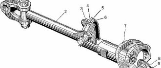
Cutting apparatus
designed for cutting the stems of the harvested crop using the direct method of harvesting and consists of a finger beam and a movable knife that performs a reciprocating movement under the action of the swinging washer mechanism in the Don 1500B, VECTOR, KZS-950 combines (Figure 7.2) or crank mechanism in the SK-5 Niva, Yenisei-1200, SK-6 Kolos combines (Figure 7.3).
Check the technical condition and adjust the cutting device.
Check shims and presser feet, cutter pins and knife guide. Check the fastening of all fingers to the corner of the beam. When lightly struck by a hammer, loose fingers make a rattling sound. Tighten the nuts on the bolts securing these fingers. Check the position of the toes and toe liners, which should be in the same plane.
When tensioning the cord between the outer fingers, the toes of the fingers should not deviate up and down by more than 3 mm, and the working surfaces of the liners should not deviate by 0.5 mm. Straighten bent fingers with light blows of a hammer. The location of the working surfaces of the finger liners in the same plane is checked with a ruler, placing it alternately on the liners of any three fingers. Inspect the back and head of the knife, the condition of the segments and rivets. Deflections in the back of the knife and incorrect position of the segments should be eliminated by straightening the back on the slab, and poorly secured segments should be re-riveted.
Check the cheeks, spring and bolt of the connecting link of the ball heads of the knife and rocker arm. The knife rocker is installed in the conical grooves of the bracket so that the connecting cheeks in the extreme and middle positions have equal deviations forward and backward relative to the knife.
When the cutterbar is adjusted correctly, the center lines of the segment 5
(Figure 7.3) and finger
7
(along the entire length of the knife) must coincide in the extreme positions of the knife (deviation is allowed no more than 5 mm).
This is achieved by adjusting the length of the connecting rod 12
with a corresponding rearrangement of the connecting rod cheeks
9
along the grooved spacers
13
.
With the correct position of the fingers, presser feet and guide, the knife should move easily with little hand effort. Check the position of the knife segments relative to the shear plate. They must be adjacent to the plates or have a gap of no more than 0.8 mm in the front and 0.3...1.5 mm in the rear (Figure 7.4). Adjust the gaps using shims, bending the presser feet, replacing or turning the friction plate over to the other side. The gap between the presser foot and the segment should not exceed 0.5 mm.
Adjustment of dividers.
For harvesting short-stemmed and non-logged grain crops with stems up to 1 m high, removable socks are used. Long-stemmed and lolled grains are harvested with reapers equipped with dividers with adjustable stem outlets and clamping rod dividers. Before starting work, the central body with internal and external stem outlets is installed so that long and tangled stems do not hang on the sides of the header and are not pulled out of the soil.
Excessive stem retraction causes loss of cut ears. Insufficient lifting of the stems and expansion of the conical part of the sidewall lead to tangled grain mass hanging on it. The position of the central housing of the divider is adjusted with a special bolt, and the offset of the stem branches is changed: the outer –
a rod and a telescopic tube, internal –
a rod
Reel
Designed for supplying the stems of the harvested crop to the cutting device and auger.
There are two types of reel: slatted and universal. Slatted is used for mowing upright grains. The universal reel captures both upright and downed stems equally well, which is why it has become more widespread. The reel is driven by a double-circuit chain transmission connected to a variator. 21
is installed on the reel shaft 5 (Figure 7.1) , designed to transmit a torque of 600
Nm
.
Reel variator.
The stroke of the movable disk is adjusted by loosening the nuts on the studs, moving the plunger all the way to the bottom of the hydraulic cylinder and evenly tightening the nuts on the studs until the gap between the disks is 25±1 mm.
In this position, bend the tabs of the lock washers onto the crosspiece. Tension the variator belt by turning the lower pulley in the oval holes so that the belt deflection at a force of 40 N
exceeds 8...10 mm.
Reel adjustment.
One of the main conditions for harvesting without losses is the correct adjustment of the reel.
To do this, set the optimal reel rotation speed and move it using hydraulic cylinders back and forth or up and down relative to the cutting device. When moving the reel back and forth, the rake angle changes automatically from -15° to +300. The reel rotation speed is set depending on the speed of the combine or windrower. The peripheral speed of the reel bar VOKR
1.2…1.8 times
greater than the speed of the machine
VMASH VOKR / VMASH = 1.2…1.8.
At a unit speed of up to 5 km/h, this ratio is taken to be 1.5...1.8, at a speed above 5 km/h - 1.2...1.5. If the ratio of the peripheral speed of the reel and the speed of movement of the unit is incorrectly selected, the reel bars do not lead the stems well to the cutting device or throw the cut stems over the wind shield, knocking out the grains from the ears. The reel rotation speed is adjusted while the combine is moving using a variator within the range from 15 to 49 min -1.
The position of the reel in height and reach is selected depending on the height and condition of the stalk of the crops being harvested. The height of the reel is set so that its slats act on the stems above the center of gravity of the cut plants, but below the ears. When the stem is impacted below its center of gravity, the plant will fall over the bar and fall to the ground in front of the header.
When harvesting upright crops with high, dense stems (over 800 mm), the reel is installed so that its rake fingers 2
touched the stems above their middle (Figure 7.5), but below the ears, i.e. approximately at distances
A > 0.5L
. Horizontally, the reel shaft is shifted back to the knife, while the rakes deviate forward from the vertical at an angle of 15°. The cutting height H = 100 mm is set by moving the header support shoes.
When harvesting erect crops with normal stems (400...800 mm long), the reel is shifted forward 40 mm from the rearmost position and adjusted in height so that the rake fingers act on the cut stems in the middle of their length ( A = 0.5L
).
The rake fingers will be in a vertical position. The adjustable cutting height is 100 mm, and on rocky soils it is 145 mm. In any position of the reel, the gap between the rake fingers and the cutting device must be at least 25 mm. It is installed by screwing in or out screws 20 (Figure 7.1) on the hydraulic cylinder rod 6
. At the same time, ensure that the reel rakes are positioned parallel to the cutting device.
When harvesting low-stem crops, the reel is lowered and moved towards the cutting device, while the rakes are tilted back from the vertical at an angle of +150. The cutting height is set to 50 mm.
Loafed loaves are removed against the direction of loafing of the loaves or at an angle to it. To do this, the reel is pulled forward as far as possible and lowered down until the fingers touch the field surface. At the same time, the rakes deviate from the vertical back at an angle of 150 or 300. The cutting height is set to 50 mm, and in fields littered with stones - 100 or 145 mm.
Header auger
designed to move the mown stems to the middle of the header and feed them to the feeder chamber. For this purpose, the screw has spirals of the right and left directions, welded to a cylindrical casing. In the central part of the auger there is an eccentric finger mechanism, which captures the stems fed by the auger spirals on both sides, as well as those cut in the middle zone, and delivers them to the floating conveyor (in the Niva, Yenisei, Kolos combines) or to beater spacers (in Don combines). The auger is installed in the header body so that a gap is formed between the spirals and the body casing in the lower part, the size of which, depending on the operating conditions of the combine, can be changed within 6...35 mm.
For a more uniform supply of mass across the width of the inclined chamber, the auger spirals partially enter the area of the finger mechanism.
The pin mechanism is made in the form of a crankshaft of a collapsible design, the ends of which are secured in ball bearings installed in the casing disks. Due to the fact that the axis of this shaft is shifted forward relative to the axis of rotation of the auger (by 68 mm), the fingers on the front side of the auger protrude from the casing (by 136 mm for Niva, Yenisei, Kolos combines and by 150 mm for combines “Don”), and on the back side they are buried in the eyes of the casing.
Therefore, the auger's finger mechanism actively grabs the cut stems in the front part of the auger, and as it moves towards the feed chamber, the fingers throw off the stems, sinking into the eyes of the casing. The zone of maximum protrusion of the fingers from the auger casing and, consequently, the degree of activity of grabbing the stems by the finger mechanism is regulated by turning the crankshaft using lever 16 (Figure 7.6).
There is a safety friction clutch on the left side of the auger 11
.
The gap between the pins 4
of the auger and the bottom of the header is set by turning the lever
16
.
By turning the lever clockwise, the gap is reduced, and counterclockwise, it is increased. When harvesting short-stemmed crops, set the minimum gap between the auger fingers and the bottom of the header - 6 mm, and the reflector visors are brought as close as possible to the auger spiral. For harvesting high-yield grains and areas with a large grain mass, as well as when selecting windrows, the gap is set to at least 20 mm, increasing it if the cut grain mass accumulates in front of the auger and the threshing apparatus of the combine operates without overload.
The optimal gap between the auger spirals and the bottom of the header for average harvesting conditions is 10...15 mm, it is adjustable with bolts 9
and
17
auger suspension (Figure 7.6).
Adjusting the header auger.
Install the auger so that the gap between the auger spirals and the bottom of the header and between the auger spirals and the visors of the reflectors of the header body is 10 mm.
Check the gap at the ends of the auger 10...15 cm from the left and right sidewalls of the header. After this, tighten the nuts on the bolts securing the plates to the sides of the header. The auger can be moved in the vertical direction (plane) by 30 mm. Set the safety clutch to transmit a torque of 300 Nm, compressing or loosening the springs on the coupling bolts. Check the torque with a special calibration wrench, and if it is not there, install a lever between the spring bolts and hang a 30 kg load on it at a distance of 1 m from the auger shaft. Evenly unscrewing the nuts on the coupling bolts, loosen the tension of the coupling springs until the lever with the suspended load begins to slowly lower. Then tighten the nuts, compressing the springs so that the clutch does not slip.
Adjust the finger mechanism so that the grain mass is evenly fed to the floating feeder conveyor and does not accumulate in the center of the header. After making all adjustments to the header auger, put on the drive chain, tensioning it by moving the tension sprocket, tighten the sprocket mounting nuts, and secure the chain drive guard housing to the header auger.
Feeder chamber of the Don - 1500B combine
consists of a housing
3
, upper drive and lower driven shafts and a chain-slat conveyor
4
(Figure 7.7).
The body has hooks 2
and coupling screws
15
for mounting the feeder chamber with a spacer.
An intermediate beater is installed in the spacer, which ensures the supply of grain mass from the header auger to the feeder conveyor. The beater is driven by a chain drive from the transmission shaft of the feeder chamber through a friction-type safety clutch. The beater is equipped with an electronic indicator that transmits information about the rotation speed to the cabin. The beater cylinder diameter is 332 mm, rotation speed is 261 min-1. The upper shaft carries a receiving pulley 5
with a safety friction clutch designed for a torque of 600 Nm.
8
of the conveyor and the drive sprocket
10
are also attached to it .
To protect the stems from winding, plastic covers are installed on the shaft. The driven shaft 18
is spring-loaded in the horizontal and vertical directions, which in combination with the runners
11
creates favorable conditions for uniform feeding of the grain mass into the thresher.
During operation, the conveyor chains come into contact with skids mounted on the feeder housing. Non-adjustable guide skids are installed under the upper branches of the chains 9
, part of the surface of which is lined with plastic linings. The pressing skids
11
are spring-loaded and installed with a gap of 5...12 mm in relation to the conveyor combs.
To adjust the gaps, there are bolts 20
.
Windrow headers
ZhRB-4.2A (Figure 7.8); ZhVN-6A (Figure 7.9); ZhVR-10 (Figure 7.10), ZhVS – 6 (Figure 7.11), etc. are designed for mowing grain into windrows.
Universal header ZHRB-4.2A
Designed for harvesting legumes, cereals, grass seeds and sugar beets, laid down grain crops. The header is equipped with an eccentric reel with a fingerless cutting device. This combination provides high-quality cutting of tangled and bent stems. In the latter case, stem lifters are installed on the header.
The cut stems are placed with a reel on a transverse belt-slat conveyor, which throws them onto the stubble from the left into a windrow. The cutting height is adjusted within 40...400 mm by changing the inclination of the gauge wheels. The pressure of the support wheel on the soil should be about 400 N. The working width of the header is 4.2 m.
Doubling header ZhVR-10
equipped with two belt-slat conveyors
1
and
3
(Figure 7.10)
,
mounted on movable frames.
The latter can be moved relative to the header body to the left and right, adjusting the position of the ejection window. When the conveyors are displaced, the reversible gearbox changes the direction of their movement relative to the resulting ejection window. When mowing high-yielding grains, the conveyors are moved apart, and a window 7
(Figure 7.10 A), into which the cut stems are thrown.
When mowing low-growing and sparse grains, use a small conveyor frame 3
(Figure 7.10 B) are fastened to the frame of the main conveyor
2
and shifted simultaneously to the left or right. In this case, the unloading window is located alternately on the left or on the right, and it is possible to form a double windrow from a strip of 20 m in two passes.
For better transverse copying, the header body is made of two sections, hingedly connected to each other. The sections are equipped with a lever-spring balancing mechanism, which, together with the support shoes of the main and support wheels of the additional sections, ensures that the header follows the field topography in the longitudinal and transverse directions.
The cutting height is adjusted by moving the support shoes and wheels vertically. The rotation speed of the reel is changed by a hydraulic variator, and the height position of the reel is changed by hydraulic cylinders. Shift the reel forward and backward along the supports and change the inclination of the rake fingers manually with the gear off.
Control questions
1. Name the main components, principle of operation and adjustment of the cutting device with a swing washer.
2. Name the main components, the principle of operation and adjustment of the cutting apparatus with a crank mechanism.
3. Name the main components, the principle of operation and adjustment of the header reel.
4. Name the main components, the principle of operation and adjustment of the header auger.
5. Name the main components and operating principle of the feeder chamber. - 1500B and Yenisei-1200 combines
6. Name the methods of harvesting grain crops, their advantages and disadvantages.
Work report: Give brief technical characteristics of the harvesters of the Yenisei-1200 and Don-1500B combines, the windrow harvesters ZhVN-6A, ZhVS-6, ZhVR-10 and ZhRB-4.2. Describe the adjustments of the cutting apparatus and feeder conveyor with the obligatory use of sketches and drawings.
Work 8 . Threshing and separating
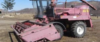
Modifications
Features of the operation of the ZhVN-6 header include periodic checking and lubrication of drive mechanisms, checking the condition of fasteners and the condition of the scythe segments.
In general, ZhVN-6 is a general designation for headers, since there are several modifications of them that differ in certain design features. So, the basic one is the ZhVN-6B header. It uses a certain type of drive, and the scythe is driven by a crank gearbox.
But ZhVN-6V, additional designation “Queen”, differs from the base one in the type of drive of the header elements, as well as the presence of a Schumacher-type gearbox.
There are other headers, for example, ZhVN-6A, but the main differences between them come down to the type of drive and gearbox. Also, some of them have wider applicability on equipment. But the main characteristics of these headers are the same.
The best brands
As is the case with any special equipment, there are recognized leaders among manufacturers of harvesting machines. The most reliable companies producing high-quality combines are:
- Combine plant in Taganrog. Manufactures the SK-6 Kolos harvesting machine. The device is undemanding to the quality of fuel and lubricants, has direct access to the main parts, so they can be replaced without dismantling the entire mechanism.
- Rostselmash. Manufactured by the Nova S300 harvester. It is one of the best machines for harvesting not only grains, but also legumes and rapeseed crops. The threshing machine is 1.2 m long and processes about 9 tons of grain per hour.
- Agromet. The plant produces the Bizon grain harvester. The equipment is equipped with a 5 m header and a thresher. The combine can be equipped with special trolleys and devices for collecting sunflowers. The car is highly comfortable, since operating settings are made by simply pressing the touch screen, and the steering wheel is equipped with a hydraulic booster.
- Claas. The company is known for its Tucano 450 combine harvester. This is a self-propelled, durable machine that has shown efficiency and high speed in the most difficult fields. Moreover, all models are equipped with comfortable cabins, touch-sensitive instrument panels, and are easy to operate and maintain.
Combine harvesters are essential equipment in agriculture. When choosing it, you should take into account the size of the area being processed and the operating principle of a particular type of machine.
Types of headers - selection according to technical parameters and scope of application
Since ancient times, grain crops were harvested using reapers. The thrifty owner used a similar device to prepare hay for animal feed and to mow sown fields.
A modern harvester mows plant stems, collects green mass, places it in windrows for subsequent processing, or feeds it into the threshing unit of a combine harvester for processing.