What is a PTO on a walk-behind tractor?
PTO, or power take-off shaft, is a mechanism designed for stable transmission of the energy generated by the engine to the working elements of attachments, stationary or mobile machines, as well as active trailers used on walk-behind tractors. Most commercially available walk-behind tractors are equipped with a power take-off shaft pre-installed at the rear of the agricultural machine. In some cases, you can also find walk-behind tractors with a PTO and differential, in the design of which the power take-off shaft is provided in the front part of the agricultural unit. The main function of the PTO on a walk-behind tractor is to solve the following tasks:
- The power take-off shaft is responsible for starting mechanical components in trailed or attached equipment. At the same time, the connection of devices used with the walk-behind tractor can be carried out either directly or through various transmission mechanisms - the latter include V-belt drives, cardan shafts and gearboxes. This is the most important function of the walk-behind tractor PTO, during which the mechanism is fully loaded;
- The PTO is also used to run the hydraulic system of the towed equipment. In this case, the PTO of the walk-behind tractor acts exclusively on the pump of the equipment used. Specifically for these purposes, the power take-off shaft is used extremely rarely, since farmers do not often use devices with hydraulic systems.
The ability to perform these functions makes walk-behind tractors with a pre-installed power take-off shaft extremely popular among farmers who own large agricultural farms.
Purpose, design, classification and operating principle of the power take-off shaft drive mechanism.
Power take-off shafts. They are designed to transmit engine power to the drive of working parts of agricultural machines. They are distinguished by location on the tractor, drive type, rotation speed and control methods.
Most tractors are equipped with a rear PTO, some with a front one. Universal row-crop tractors have a rear and side PTO.
Based on the type of drive, PTOs are divided into asynchronous (dependent, independent, semi-independent) and synchronous. With a non-synchronous drive, the PTO receives rotation from the engine crankshaft directly or through the clutch shaft. The PTO with a dependent drive is driven into rotation through the clutch shaft and stops when the clutch is disengaged.
The independently driven PTO receives rotation from the engine crankshaft through the drive part of the clutch, regardless of whether it is disengaged. With a semi-independent drive, the PTO rotates when changing gears, while stopping, but does not turn on and off when the tractor is moving. This PTO is used with a double-flow clutch. For a PTO with a synchronous drive, the rotation speed changes when changing gears in proportion to the speed of the tractor.
A synchronous drive is used on row-crop tractors to drive the working parts of machines, the speed of which must be coordinated with the speed of the tractor (for example, mounted seeders).
With a synchronous drive, the PTO shaft receives rotation from the driven shaft of the gearbox.
The PTO rotation speed with a synchronous drive is standardized: 9 s-1 (540 mshg 1) and 16.6 s" 1 (1000 min" 1). It does not depend on the tractor gear and is constant at a constant crankshaft speed. The PTO shanks are located at the same height from the level of the tractor's supporting surface, but have different splines: 8-spline for 540 min'1 and 21-spline for 1000 min'1.
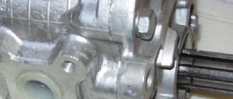
The rotation speed of the two-speed independent PTO drive is switched using a driver installed under the bottom of the clutch housing, acting on the PTO fork shaft 22. The fork moves the coupling 23, sliding along the splines of the PTO drive shaft 18. With its external and internal teeth, it can engage with gears 24 or 25 of the PTO drive of the second and first stages, which are placed freely: one on the smooth part of the shaft 18, and the other on the hub of the gear 25. If the PTO is not used, then its protruding end covered with a cap stamped from sheet steel or plastic.
PTO control methods are mechanical and hydraulic. PTOs with simple mechanical control are usually equipped with a dependent drive. It consists of housing 2 (Fig. 24), in which a pair of spur gears is placed. The driven gear 7 can move along the splines along the shaft. It is engaged in engagement with drive gear 4 only when the tractor is completely stopped. Oil supply gear 6 is placed on a bearing mounted on the driven gear hub and provides oil supply to the drive gear bearings when the PTO is disengaged.
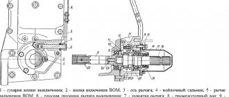
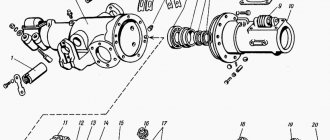
Rice. 24. Power take-off shaft with a stepped gearbox (DT-75ML tractor):
1 and 5 - drive and driven shafts; 2 - body; 3 — breather plug; 4 and 7 - driving and driven gears; 6 — oil supply gear; 8 — oil drain plug; 9 - pallet
Power take-off shafts with independent drives can be turned on and off when the tractor is moving using a hydraulic control method or a complex mechanical drive (via a planetary gearbox).
The PTO with a planetary gearbox consists of a crown and sun 7 (Fig. 25) gears, three satellites 10 placed between them, a carrier 8 and two brake drums with brake bands.
The sun gear hub 7 is rigidly connected to the brake 5, which rotates freely on the shaft 6. The brake 11 is connected to the carrier 8 through the axes of the satellites 10, and the carrier is rigidly connected to the shaft 6. A replaceable shank is installed at the rear end of the shaft. Steel brake drum bands with friction linings are fixed at one end to a fixed axis, and the other is connected through adjusting screws 3 to the PTO control lever.
If the PTO is turned off, then brake 5 (Fig. 25, a) of the sun gear is lowered, and brake 11 of the carrier is tightened. Shaft 6 is stationary, and satellites 10 transmit rotation from the ring gear to the sun gear 7.
When the PTO is turned on, brake 5 (Fig. 25, b) of the sun gear is tightened, and the carrier brake 11 is released and the satellites roll along the stationary sun gear, and their axes rotate the carrier and shaft 6. The extreme upper and lower positions of the PTO control handle 1 are held force of the compressed spring 4.
The drive shaft of the planetary mechanism is turned on by lever 2 acting on gear coupling 4.
Rice. 25. Scheme of operation of the PTO of the MTZ-80 tractor with a planetary gearbox:
a and b - PTO is turned off and on; 1 — control handle; 2 - traction;
3 - adjusting screw; 4 - spring; 5 — sun gear brake;
6 - driven shaft; 7 — sun gear; 8 - carrier; 9 - drive shaft
with ring gear; 10 — satellite; 11 - carrier brake
To engage the synchronous PTO drive, the clutch is moved to the extreme forward position, and the PTO receives rotation from the secondary shaft of the gearbox through gear 1. With independent drive of the rear PTO, the clutch is moved to the rearmost position and the PTO receives rotation from the engine through a pair of gears located in the clutch housing , and rear axle.
Side PTO. A side PTO can be installed on the tractor, which facilitates the drive of mechanisms of agricultural machines located in front and on the side of the tractor. The side PTO is installed on the left side of the gearbox instead of the side cover.
From Wikipedia - the free encyclopedia
Power take-off shaft and attachment and lifting units for attachments on a wheeled tractor.
Power take-off shaft (abbr. PTO) is a unit of tractors, less often trucks, that transmits rotation from the engine to attachments, active trailers and other mechanisms.
The vast majority of modern tractors are equipped with a PTO. However, there are still old tractors without a PTO (for example, DT-55).
In most cases, tractors are equipped with a rear PTO and, accordingly, a rear three-point linkage (three-point).
Less common is equipment that must be located in front of the operator for the convenience of the operator. In this case, tractors can be equipped with a front PTO.
PTO control "MTZ-82"
The planetary gearbox of the power take-off shaft on the MTZ-82 is controlled by 2 band brakes. The first brake drum is welded to the carrier, the 2nd drum is connected via a splined coupling to the sun gear.
To turn on the MTZ-82 power take-off shaft, the control lever in the cab should be moved to the rearmost position. The brake on the sun gear drum is applied while the brake on the carrier is released.
From the ring gear, rotation is transmitted through the satellites to the carrier, and then from it directly to the shaft. The rotation speed decreases at this time according to the gear ratio of the planetary gearbox - by 1.47 times.
When you need to turn off the PTO gearbox, the control lever is moved to the extreme forward position. The brake on the sun gear drum is released, and the carrier brake is tightened. In this position, the carrier does not move, and the ring gear runs idle on the satellites. At the same time, the satellites rotate, also idle, the sun gear relative to the carrier hub.
The rotation speed of the power take-off shaft is switched by means of a clutch mounted on the shaft spline. The mechanism that does this is a hexagon located in the bottom cover of the one-piece clutch housing.
Types of shafts and principles of their operation
The abbreviation PTO, stands for power take-off shaft, is equipped with walk-behind tractors and tractors. It is most often located at the back, front or side.
With the help of a PTO, torque is transmitted from the engine drive axis to mechanisms that are attachments. These shafts can be divided into 4 types:
- dependent;
- independent;
- synchronous;
- asynchronous.
The dependent power take-off shaft and clutch rotate simultaneously. When the clutch is disengaged, the driveshaft stops. It affects the operation of a walk-behind tractor or tractor under the following operating conditions:
- stopping the machine operation entails stopping the PTO;
- when accelerating the unit, shaft rotation is limited;
- The shaft can only be disconnected when the tractor is completely stopped.
Such a power take-off shaft on the tractor is controlled using a lever located in the tractor cabin, and only after the clutch is disengaged. When the lever is in the lower position, the PTO is turned on; when the lever is raised up, it turns off. If debris gets into the mechanisms, the tractor must be stopped without turning off the selection drive. The tractor should be allowed to restore its normal load level and then continue working.
The independent PTO is not connected to the clutch, so all the disadvantages associated with it are completely or partially absent. This allows you to load the drive evenly, turn on additional mechanisms when the engine is turned off, start the mower to full operating speed and, upon approaching the field, begin to mow the grass. The independent shank makes working on the walk-behind tractor easier.
Synchronous cardans include those that rotate simultaneously with the main wheels of the walk-behind tractor. They operate stably only at a constant rotation speed.
The speed of non-synchronized axles is not linked to the tractor speed. They are used for mechanisms that produce spraying, hay harvesting, for pumping hydraulic systems and others.
As a rule, the PTO is located at the rear of the walk-behind tractor or walk-behind tractor. It powers devices such as:
- mowers;
- harrows;
- watering equipment;
- cutting devices;
- seeders;
- stump removal device;
- sweepers.
This list can be continued with several dozen more samples of mounted installations. The shafts operate at standard speeds of 540 rpm or 1000 rpm.
Its working part is also called the shank. It connects to the driveshaft of the attachments or, less commonly, to their hydraulic pump. The connecting part of the attachment shank must be commensurate with the power take-off shank. If they do not match in size, then a transition device is used. But its use will reduce the reliability of the structure in the event of a sharp increase in workload.
Nowadays, a modern walk-behind tractor with a power take-off shaft often has a front-mounted shank. This is very convenient when you need to remove snow or mow the grass.
Dependent and independent PTO
A dependent shaft is a shaft that is driven into rotation together with the clutch and stops when it is turned off. A diagram of such a shaft is given in Figure 137, a. The coupling shown in the figure on the right is used only to disengage the PTO when the clutch is disengaged. A dependent PTO limits the use of a tractor with driven machines for the following reasons:
- when the tractor stops to change gears, the PTO rotation stops;
- during the acceleration period of the tractor, the PTO operates at partial speed;
- To stop the PTO (for example, when turning the machine), you need to stop the tractor.
Independent is called a BOM that receives rotation from the engine crankshaft, in addition to the clutch, so it is partially or completely devoid of these disadvantages. The diagram of an independent PTO is shown in Figure 137.6. Having such a PTO, you can turn on working parts, such as mowers, when the tractor is parked, give them normal speed, and only then enter the paddock to mow grass. When working with such a PTO, the engine is loaded evenly, during operation the unit has no unnecessary stops, and control of the unit is easier.
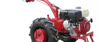
Motoblock drive motors
A walk-behind tractor with a domestically produced power take-off shaft has a drive that consists of a classic internal combustion engine. Units classified as light or medium are equipped with four-pin gasoline engines. Some outdated walk-behind tractors still have two-pin gasoline engines.
Machines considered heavy most often have diesel engines, the operation of which is ensured by the following systems:
- fuel receipts;
- cooling;
- lubricants;
- starting - starter;
- gas distribution;
- ignition
The engine crankshaft transmits rotation to the gearbox through its gearbox. It is possible to stop such a unit without stopping the drive. When changing gear, the gearbox is disconnected from the engine. This prevents jerking when the walk-behind tractor with the power take-off shaft starts moving, and you can also stop the unit without turning off the drive.
The coupling occurs through the clutch. The clutch is controlled using a lever. To ensure that the walk-behind tractor operates smoothly and without jerking, an additional unit is installed on heavy machines - with a differential. This mechanism eliminates the parallel rotation of the wheels, which makes it possible to set the wheels to different rotation speeds.
Maintenance of PTO "MTZ-82"
Maintenance of the power take-off shaft of the MTZ-82 tractor consists, first of all, of regular inspection of threaded connections and checking them, as well as periodic adjustment of the control mechanism. The PTO mechanisms, which are located in the rear axle housing, are lubricated with oil poured into the transmission.
The independent drive should be turned on at the minimum speed of the diesel engine. The synchronous drive is activated when the engine is running after engaging the gear, when the clutch mechanism is smoothly engaged.
During operation, it is necessary to periodically carefully monitor changes in the position of the PTO control lever, not allowing it to rest against the floor of the tractor cabin (as this will lead to slipping of the brake bands).
If the stroke of the control lever has increased, or the force on the lever has increased noticeably when moving it from the “on” to the “off” position, this indicates that adjustment is necessary.
The MTZ-82 power take-off shaft is adjusted according to the following plan:
- Setting the eccentric axis to its original position. The mark, which is specially applied to it, should be on the right side and located in a vertical position.
- Fixation of the installed position using locking plates.
- Traction disconnection. Unscrewing the bolts on the glass and releasing the spring.
- Removing the cover from the rear axle hatch to get to the head of the tension screw. Moving the lever to the neutral position and fixing it with a bolt.
- Removing the locking plate, tightening the screw until it stops. Screwing the thrust bolt into the outer glass. Move the lever to the “on” position. Installation of traction. Establishing the required lever play.
After the adjustment is completed, return all the parts to their places, strengthen the rods and fastening bolts with locknuts.
In the process of disassembling the cup, PTO with a compressed spring installed in it, it is important to be careful and perform all operations carefully, in a certain sequence. To disassemble and reassemble a glass with a compressed spring, it is best to use a press or clamp.
Rear PTO
The rear shaft is a combined mechanism, that is, it can operate in two modes:
- Independent. In this mode, the number of shaft revolutions depends on the tractor engine speed. The drive, connected through a clutch to the diesel flywheel, provides two operating frequencies - 540 rpm and 1000 rpm at engine speeds above 2100 rpm.
- Dependent (or synchronous). In this mode, the shaft speed is determined by the speed of the tractor. In this case, the PTO receives rotation directly from the gearbox. The shaft rotates 3.5 turns per 1 meter of distance traveled by the tractor. Accordingly, the higher the speed, the faster the PTO will spin.
Synchronous and non-synchronous PTO
Shafts are called synchronous , the speed of rotation of which varies in proportion to the speed of rotation of the drive wheels of the tractor. Such shafts are used to drive seeding units of mounted seeders and other machines, the operation of which must be coordinated with the speed of movement of the unit.
For non-synchronous shafts, the rotation speed does not depend on the speed of the tractor drive wheels. Such shafts are designed to drive tractor hydraulic system pumps, working parts of dusters and sprayers, hay harvesters and other machines that operate normally only at a certain constant speed mode. The speed and direction of rotation of non-synchronous shafts and the dimensions of their splined end are standardized for all tractors.
Universal row-crop tractors MTZ 80, MTZ 82 are used to perform a wide range of mechanized work, including aggregation with various active, mounted, trailed specialized mechanisms. To transfer power from the tractor to the equipment used, the equipment of the above brand is equipped with power transmission shafts. The drive is carried out from splined tips connected by appropriate couplings to the machines being aggregated.
The main features of walk-behind tractors with a power take-off shaft. Advantages and disadvantages of PTO.
When people first apply for a walk-behind tractor, they have a rough idea of what will be an absolute advantage and what they want to see in their unit. Here is a sample list:
1. Powerful engine.
3. Branded manufacturer.
POWER TAKE OFF SHAFT - PTO.
Most often, these requests indicate a desire not to make a mistake with the purchase, but a lack of understanding of the principles of working on a walk-behind tractor with a site can play a cruel joke.
Chinese
The main difference between Chinese walk-behind tractors and competitors from other countries is their low cost. If such a price level is ensured due to mass production, that’s one thing. But sometimes the Chinese, in an effort to reduce costs, complete their products with low-quality parts. Therefore, when purchasing products from the Middle Kingdom, you need to carefully look at the history of the manufacturer and study reviews of consumers of such products.
The main technical characteristics and operating capabilities of walk-behind tractors produced in different countries differ slightly. Nevertheless, it is worth familiarizing yourself with the most popular and powerful diesel models of Chinese manufacturers in more detail.
Forte HSD1G-80
This budget model is considered the best cultivator among walk-behind tractors, since it was originally created for this purpose, only later it was given additional functionality.
Characteristics:
- middle class walk-behind tractor;
- petrol engine 4-stroke H168FB, 198 cm³, 6 hp;
- processing width - 80 cm;
- number of gears: 2 forward speeds and 1 reverse;
- weight - 85 kg;
- pneumatic wheels.
Weima WM1100B (10012)
This mechanism belongs to the heavy class. A powerful diesel engine provides it with high torque, and a gear reducer, made according to the best Western models, ensures reliable operation of the chassis.
Characteristics:
- heavy-duty walk-behind tractor;
- diesel engine 4-stroke WM186FB, 406 cm³, 9 hp;
- processing width - 110 cm;
- manual gearbox, 2/1;
- weight - 128 kg;
- pneumatic wheels;
- disc clutch;
- gear reducer.
Kipor KDT 910C
Another representative of diesel mechanisms. Users describe it as one of the most reliable models made in China.
Characteristics:
- heavy-duty walk-behind tractor;
- diesel engine 4-stroke KAMA KM186FS, 296 cm³, 8.6 hp;
- processing width - 90 cm;
- manual gearbox, 3 forward and 1 reverse speeds;
- weight - 135 kg;
- pneumatic wheels;
- clutch - tension roller;
- gear-chain reducer.
Main PTO functions
First of all, you need to know that the power take-off shaft is a device for transmitting engine energy to the moving elements of the implement or mechanisms working in conjunction with the walk-behind tractor. In machines, in most cases, the drive mechanism of agricultural implements is connected to the power take-off shaft using a splined bushing. This connection method significantly increases the reliability of the mechanisms and increases their service life.
Most of the entire range of units is equipped with a shaft, which is installed at the rear of the walk-behind tractor. But sometimes there are agricultural machines equipped with a PTO located on the front side of the unit.
Let us list the tasks that the power take-off shaft performs.
- Starting and functioning of the mechanisms of mounted implements. It is worth noting that equipment units can be driven either directly or using belt drives, gearboxes or cardan shafts. The degree of load on the mechanism changes depending on the connection principle.
- Sometimes a power take-off shaft can be useful for operating trailer hydraulic systems. In this case, the shaft acts directly on the hydraulic pump. But for such functions, a PTO is rarely needed, because summer residents very rarely use implements with hydraulic systems.
The ability to implement the described tasks has made walk-behind tractors with a power take-off shaft very popular among owners of large summer cottages.
Practical tips for use.
The design features of the drive shafts of the machines used often have the character of open, actively rotating parts. To avoid injuries and emergency breakdowns when working with drive machines, you should be careful and take into account the following aspects and rules:
- The machine coupled with the tractor must be in good technical condition.
- The machine must be used strictly for its intended purpose and in appropriate conditions. When preparing for PTO operation, you need to make sure that the splines of the shaft shank and the drive coupling of the machine used match (8 splines or 21). If there is a discrepancy, the shaft shank must be replaced.
- Check the presence and reliability of fastening of protective covers, rotating parts of the drive machine, adjustment of the safety clutches and serviceability of the cardan joints of the drive.
- The drive is installed directly at the place where the unit is used. The connection is secured with a special locking bolt when the recess on the shaft splines coincides with the hole in the coupling of the cardan drive of the machine being aggregated.
- The route and turning radius must correspond to the design features of the unit.
- In order to avoid overloading the unit structures, the choice of movement speed, processing depth, working width, and operating mode of the unit must comply with the standards and requirements.
- Disconnection is done after the shaft has completely stopped in the neutral position of the drive mode switching lever and the PTO is turned off.
With an optimal balance of engine speed and load, a significant reduction in fuel consumption per unit volume of work done by the unit is achieved. If the agrotechnical and technological conditions of the work do not limit the speed of the unit, the gear is selected based on the optimal load without signs of overloading the tractor and the mechanisms of the drive machine used. When working with energy-intensive machines with insufficient engine power, in a situation where the unit’s performance is not fully loaded at speeds above 7 km/h, a gearbox reduction gearbox is used.
In today’s article we will take a detailed look at such a mechanism as the power take-off shaft of the Belarus MTZ-82 and MTZ-80 tractors, its diagram and principle of operation, and also provide complete instructions for its disassembly and basic repairs. Why two models at once, you probably ask? – because their design is absolutely identical.
Dependent type PTO
Clutch-dependent gearboxes are installed on vehicles with manual transmission. This mechanism is installed if there is no need to turn on attachments on the go. For example, the power take-off box of a dump truck is often made in a dependent design.
The main advantages that KZOM has:
- light weight;
- ease of repair of power take-offs;
- no load on the engine when the PTO is off;
- simplicity and reliability of the design, allowing you to confidently operate both new and repaired boxes, which is confirmed by an extensive sample;
- low maintenance requirements;
- increased safety, since the drive cannot be activated while moving, which is especially important for a dump truck PTO.
PTO localization is another detail that cannot be missed
Units that will subsequently be mounted on tractors can be located not only at the rear, but at the front and even on the side.
This means that the PTO, or rather its localization, can also be “floating”. On the rear traverse of the tractor, you can install a rear PTO, where, in addition to it, transmission elements are located. In the case of a side PTO, a housing made of either metal or plastic is used, which is tightly fixed to the gearbox. In order to “pull” the cardan shafts to them, which will act as rotation transmitters, the ends of the shaft are left open. They look like short slotted rollers. A PTO for a homemade mini tractor is an important solution that allows you to make your home equipment modern and maneuverable. Moreover, in terms of their technical characteristics, such homemade products, which almost anyone can make in their garage or backyard, will be absolutely no worse than production ones. By changing adapters, such equipment will work both in summer and winter, which is especially important for owners of country houses or farms.
Varieties
As you already understand, PTO is used on machines to transfer energy to additional equipment.
Based on the mechanisms being driven and the requirements for the device, there are different types of existing power take-offs. They may differ from each other according to several principles:
- Number of steps. This defines the pitch between the available working mechanisms.
- Presence of reverse. Some components, such as pumps, only rotate in one direction. If this is a truck crane, then the PTO should work in two opposite directions.
- Gear ratio. The change in angular velocity and transmitted torque depends on this value.
- Number of shafts. It may vary depending on the design of the particular box.
- The location of the components that are included in the box.
- Control special signal. It can be mechanical, using a lever or through the on-board computer.
When getting acquainted with the design of power take-off boxes, you should definitely take into account possible options for their location.
Basically, systems can be installed at the following points:
- on the side relative to the vehicle’s gearbox;
- on the end side of the box;
- in the gearbox housing;
- together with the transfer gearbox.
The PTO requires mandatory lubrication, which depends on the installation features and the presence of its own oil reservoir in the design. Most often, lubrication is carried out using oil and the crankcase of the main box.
It also happens that the PTO has an upper location. In this case, a pump is additionally used. It allows lubricant to be supplied to the assembly.
All boxes used on machines can be divided into several subcategories. They are:
- reversible;
- gearless;
- dependent;
- independent.
Each option requires separate consideration for a better understanding of the essence and operating principle of the device.
PTO for a homemade mini tractor: we make it at home
In order to make this engineering dream come true, you can use one of the proposed drawings.
According to the diagram below, the design of the future PTO includes several basic elements:
- front frame;
- drive sprocket;
- driven sprocket;
- additional selection shaft;
- bearing in the amount of 2 units. – it is better to take ready-made ones, removed from old agricultural machinery;
- brake.
The assembly will look as shown in the installation diagram for the second drawing.
Reversible systems
Such PTOs have a gearbox, and the shafts are arranged longitudinally. Installation of such units is carried out in the lower side part of the machine’s gearbox housing.
Here, power take-off is realized through the gearbox intermediate shaft gear. It is in a state of constant, strong engagement with the block gear, of which there are several in the circuit. Another gear will be in mesh with the idler gear. The gear block itself, as well as the intermediate gear, are located on the axes. The latter are fixed directly to the PTO housing.
Side PTO
Side PTO is installed to drive mechanisms mounted on the front linkage or on the side of the tractor. A separate gearbox housing of the independent “Side PTO” is attached to the hatch on the left side of the MTZ 80(82) gearbox housing. The drive is carried out from the driven gear of first gear and reverse gear. The drive shaft has a standard eight-spline end and is covered with a protective cover.
The “Side PTO” activation lever is located above the floor on the left side of the driver’s seat. Activation is carried out by moving lever 1 upward, while rod 2 turns the lever and the roller with the driver, moving the gear on the splines of shaft 7 , bringing gear 4 into engagement. “Side PTO” is engaged when the clutch is disengaged.
By switching the reduction gearbox, two shaft rotation speeds of 535 and 735 rpm are obtained in independent mode.
The “Side PTO” synchronous drive is used on tractors of the cotton modification MTZ 80X. The drive is carried out by a gearbox from the drive gear of the final drive of the rear axle. If the tractor is equipped with a parking brake, the side synchronous shaft is installed only on the left. Installation of a separate gearbox is carried out to the rear axle brake housings. The connection is made using a splined coupling. The control lever is brought into the cabin. Synchronous drive shafts are installed perpendicular to the axis of movement of the tractor.
Gearless mechanisms
In addition to the geared PTOs that were discussed above, there are also gearless gearboxes designed for power take-off. Their distinctive feature is the simplicity of their design. They also have a single gear ratio.
To select the required power in this case, a transfer case input shaft is used, at the end of which special splines are provided. These types of boxes are mounted on the end part of the transfer case housing in the upper part of the structure.
The PTO shaft at one end has similar splines as the transfer case primary shaft. At the other end, a flange is installed to secure the drive shaft of additional automotive equipment.
To turn on the selection box, you need to lock the two shafts using a special carriage. The latter moves due to the power fork located on the rod. The rod has two fixed standard positions. If this is the left position, then the selection box is in active, that is, working condition. The right position means that the PTO is off.
You can change the direction of rotation of the PTO shaft by engaging reverse gear at the vehicle's gearbox.
If you study the design of the box in question, you will notice one important nuance. This is the use of a plunger pump. It is needed to lubricate the components of the PTO housing and transfer case at a time when the car is stationary, but additional equipment is working. This prevents possible wear of parts due to lack of lubrication. The pump forcibly supplies oil to the components, thereby lubricating and cooling them.
The plunger-type pump itself is installed in a housing located directly in the boss of the PTO cover. It includes the plunger pump itself, as well as a non-return, suction and mandatory discharge valve.
To control such a selection box, a lever is used, directly connected to the rod and located in the cabin of the machine or other vehicle.
The operation of power take-offs without a gearbox has been sorted out. Now it’s worth looking at 2 more types of knots.
Adjustment.
Adjustment of the friction tapes of the PTO gearbox and the engagement lever is carried out in the following order:
- The shift axis is fixed by aligning the holes on the lever and the housing of the rear axle 7 of the tractor with a 5 m10x60 mm bolt.
- Disconnect the spring amplifier from the lever (following the above dismantling procedure), having previously compressed the spring with a bolt and secured it in a compressed state with a locking bolt 1 screwed into the hole in the amplifier housing 2 .
- The adjusting screws 8 bands are screwed in all the way without excessive force, then released one and a half turns. In this case, the PTO shaft shaft should rotate freely under the force of your hand. If rotation is difficult, unscrew the screws another “half turn”.
- The position of the screws is fixed by a plate in the cover that closes the adjustment hatch.
- By connecting the lever to the fork, adjust the position from the lower plane of the cabin floor to the control lever fork. In the on position, the distance should be 45-50 mm. The articulated forks on the threads of the lever are fixed with control nuts.
Possible faults
Possible breakdowns, repairs and malfunctions:
- Jamming of the shaft handle on machines: turning on requires a lot of effort from the driver. In this case, it is recommended to inspect the spring cup or cam-type coupling for damage and wear of parts.
- Increasing extraneous noise as torque increases. Such a malfunction may be associated with wear of the PTO splines and elements of the planetary gear mechanism. It is also worth inspecting the cuffs for elasticity and damage.
- The shaft is unstable and jerky. The breakdown may be related to the splined connections of the mechanism. Either the gear moves too freely along the base, because her teeth were worn out. It is necessary to disconnect the rear axle from the dog clutch. Inspect the width of the gaps. If the gap is too large, it is recommended to replace the shaft.
- The engine is not running at full power. The band brakes should be replaced and adjusted.
- The tail shaft moves too freely. In this case, it is recommended to tighten the loose nuts. Threads may need to be replaced.
Traces of grease on the shaft cover may be a sign of worn cuffs or gaskets of the mechanism. It is necessary to remove the PTO and replace damaged system elements.
PTO malfunctions
1 The inability to switch modes is caused by wear of the jaw clutch. In this case, disconnect the gearbox from the rear axle mechanism and replace the worn parts. 2 If the shaft continues to rotate after being turned off or the stability of the PTO rotation speed in the on position is disturbed, in such cases the brake bands should be adjusted or replaced.
3 Difficult switching on or impossibility of switching on indicates a breakdown of the spring switching amplifier. Eliminate by replacing the spring.
Please note that in order to avoid injury, dismantling and installing the spring amplifier is done in strict sequence:
- Move the power lever to a position in which the holes on the lever and the rear axle housing coincide.
- A bolt is screwed into the holes to secure the lever.
- The control nut 4 on the adjusting bolt 5 cup 2 , and the bolt is screwed in over the entire length of the thread, compressing the spring 1 .
- The locking bolt securing the spring is tightened in the cup body.
- Having fixed the spring, unscrew the adjusting bolt and remove the amplifier. Using a press, disassemble the glass and replace faulty parts.
- Assembly and installation of the unit is carried out in the reverse order.
Planetary gearbox rear PTO MTZ
4 The appearance of hum and noise during PTO operation indicates wear of the bearings and parts of the planetary gearbox. To eliminate the breakdown, the gearbox is removed from the rear axle housing and the unit is completely disassembled, followed by defect detection and replacement of parts.
Top best models
Below are several models that most interested users and, in their opinion, were among the best units. From them you can choose and buy the best unit for yourself.
Salyut 100-X-M1
This device is equipped with a 6.5-horsepower Honda gasoline engine, a 3.6-liter fuel tank, a gear transmission, and a power take-off shaft to allow the use of a wide range of attachments. All important components, including the pulley, are placed in a plastic casing, which reliably protects them from dust and foreign objects. The handle has a speed mode switch (2 forward, 1 reverse), which makes it convenient for the operator to control the walk-behind tractor. Its processing width is adjustable and can be set at 30/60/90 cm. The weight of the product is 78 kg, the cost is about 48,000 rubles.
Neva MB-23
The device is equipped with an American Briggs&Stratton 10 hp engine. and is designed for intensive, heavy work. To equip it, a gear-chain gearbox and a 3-speed gearbox are used. Distinctive features of the Neva MB-23 motor unit are 140 mm ground clearance, adjustable track (normal 320 mm, with extensions - 570 mm), good traction indicator equal to 160 N (kgf). This walk-behind tractor can work on all types of soil and even cultivate virgin soil. Its weight is 105 kg, and the average cost is 50,500 rubles.
Agate KhMD-6.5
The model is equipped with a Japanese-made 6.5-horsepower diesel engine and is perfectly adapted to harsh operating conditions. It consumes fuel economically (up to 1.2 l/hour) and demonstrates high performance. This walk-behind tractor is equipped with an improved muffler design, which provides low levels of vibration and noise, and large pneumatic wheels, allowing it to easily move across the field. Its processing width reaches 90 cm, and the plowing depth is 25 cm. The weight of the unit is 85 kg, the cost is 25,600-29,300 rubles.
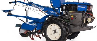
Scout 135DE
To equip the Scout 135 DE walk-behind tractor with a power take-off shaft, a four-stroke diesel engine with 9 hp is used. with a 5.5 liter fuel tank. It is equipped with 10 cultivation cutters, providing a working width from 75 to 135 cm and a plowing depth from 8 to 30 cm. This unit is very powerful and is designed for processing large areas. It has high cross-country ability even in uneven terrain, where it is difficult for conventional motor vehicles to properly loosen the soil. Its weight is 142 kg, and the price starts from 52,900 rubles.
Huter GMC-9.0
This is another representative of heavy garden motorcycles equipped with a power take-off shaft. The model is equipped with a four-stroke engine with a power of 9 hp, a 5-liter fuel tank and has a three-speed gearbox with a reverse function. In one pass, it provides processing of a strip with a width of 115 cm. The unit is characterized by good stability and maneuverability due to the presence of large pneumatic wheels. Its weight is 135 kg. The price for it starts from 43,800 rubles.
Sources
- https://dostavka99.ru/specnaznacheniya/chto-takoe-vom.html
- https://oxotnadzor.ru/kakiye-byvayut-valy-otbora-moshchnosti/
- https://dlobal.ru/vom-val-otbora-moshhnosti-na-minitraktor-svoimi-rukami/
- https://1sadteh.ru/komplekt/val-otbora-moshhnosti.html
- https://tractoramtz.ru/prochie/chto-takoe-val-otbora-moshhnosti.html
- https://lkard-lk.ru/avtolyubitelyu/val-otbora-moschnosti-chto-eto-takoe
- https://usbravo.ru/dlya-chego-nuzhen-mekhanizm-otbora-moshchnosti/
[collapse]
Popular models of walk-behind tractors with PTO
When choosing the device you need, you should focus on the types of work that you plan for it. What matters is the nature of the soil and the size of the land plot to be cultivated. The most expensive models of walk-behind tractors with maximum functionality are not always the right choice. It's not worth paying for features you'll never use.
So, in large areas with dense soil, choosing a heavy walk-behind tractor would be optimal, while in the country a light model is sufficient. You should definitely determine the type of fuel on which your future purchase will run. The advantages of gasoline are quieter engine operation, ease of maintenance and light weight. A diesel engine is noisier than a gasoline engine, less environmentally friendly, but has more power and sufficient torque. A unit with a diesel engine is good for processing large areas, but its disadvantage is its high cost.
You should also look at attachments that are compatible with the walk-behind tractor model you choose. After all, often the necessary additional unit is manufactured by another company, and an adapter is required to connect it and work with your device. This reduces operational reliability and can lead to unexpected breakdowns.
There are many models of walk-behind tractors on the market. Judging by customer reviews, the most popular are models produced by Husqvarna, Patriot, Hyundai, Daewoo. Among the largest manufacturers in the CIS, the following brands are represented: Belarus, Neva, Salyut-100, etc. And we cannot forget the Chinese companies Forte, Wiema, Kipor, whose products are also in demand.
MTZ tractor PTO: design and adjustment
A side shaft is necessary for mechanisms that are mounted on the left side (if a parking brake is installed on the tractor) or in front of the device. A separate side PTO housing is located to the left of the gearbox housing, and it is attached to the hatch. This mode can be activated using the lever located to the left of the driver above the floor. As soon as the lever moves upward, the gear is brought into engagement by moving it on the shaft spokes, which, in turn, are driven by a rod that turns the roller with the driver and the lever itself.
It is necessary to regulate the PTO to restore and maintain its performance. If this is not done, the special equipment for the tractor will simply lose its functionality, as a result of which expensive repairs will have to be carried out. Situations for adjustment:
- noise from the rear axle;
- the shaft shank moves very freely;
- the appearance of oil smudges on the shaft cover;
- the occurrence of a metallic knock or grinding sound when the maximum load is applied;
- When working with attachments, the tractor does not produce the stated maximum.
The adjustment must be made in strict accordance with the algorithm:
- The vehicle must be installed on a special viewing platform.
- The eccentric axis should be set to its original position.
- The right vertical position is the position of the flat cut at the shaft.
- The next step is to disconnect the rod, for which you need to unscrew the bolts that secure the satellite and secure the springs.
- The process of turning out the fasteners is perhaps the most important: until the spring straightens, the outer glass must be in direct contact with the bolts.
- You can access the regulator by removing the hatch from the rear axle.
- To fix the control shaft, you need to install a bolt in the hole, which is located on the lever in the rear axle housing.
- As soon as access to the control roller is gained, all that remains is to remove the stopper plate and fix the fastener until it stops.
- When all 7 points of manipulation are completed, you need to remove the bolt that supports the lever. Then screw in the thrust bolt so that it is about 26-30 mm - it is within these limits that its free length should vary. We set the control roller lever to the “on” position, set the thrust, adjust, using the adjustment lever, swing the control lever to the optimal zone.
The adjustment procedure is now complete, but do not forget about the previously removed plates from the shaft cover, which must be installed in place.
Although the PTO shaft adjustment should be carried out regularly, there are times when it is necessary to further adjust the band brakes. This is especially necessary if the PTO starts to slip, the handle rests against the slot during shifting, the PTO is unstable, or it is impossible to lock the control lever. To troubleshoot problems, you need to:
- Set the lever to the neutral position.
- Secure the lever using the stopper.
- Dismantle the plate.
- Adjust the eccentric axis.
By turning the shank by hand, you can check the quality of the adjustment. If this is not possible, then everything went well. All that remains is to remove the clamps and install the plate in its place. And if the axle has shifted at the brake mechanism to the left side of the tractor body, it means that the power unit has used up the correction reserve. To correct this, the eccentric will need to be turned counterclockwise, thereby returning it to its original position. And re-adjust the shaft.
Side PTO
The side PTO consists of a movable gear wheel through which the drive is carried out. And by means of a driver, the gear moves along the splines. With the help of rod 3 and always with the clutch disengaged, the side shaft is turned on.
Rear PTO
Schematically, the MTZ rear power take-off shaft includes:
- coupling mechanism support disk;
- gear parts of driven and driving types;
- independent two-speed shaft;
- semi-independent side PTO;
- clutch gear coupling;
- driven type PTO;
- shaft of secondary and intermediate types;
- retaining bolt;
- carrier with brake drum;
- gear drive parts;
- brake mechanism.
The main mechanism of the tractor is a switching device between two drives and a rear-type gearbox with two stages. The clutch located on the spline of the machine determines the rotation speed. And the hexagonal element, which is located on the clutch housing cover, is responsible for controlling the PTO.
The drive begins to work when the cam mechanism is switched: when the lever is moved forward, the entire system comes into action. When the handle is moved to the “Off” position, the system stops working. In general, the lever can be set in one of three positions: turning it counterclockwise turns on the independent type of drive, turning it clockwise turns on the dependent type: both types must be turned on when the engine is not running, or when the crankshaft has the lowest rotation speed. The middle position sets the synchronous type (the tractor must be stopped first).
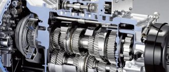
PTO composition
The main component of the power take-off shaft is a two-speed gearbox, a switch between independent and planetary and synchronous gearboxes. It is the planetary gearbox that is the most important mechanism, responsible for one of the types of drive and changing the torque.
Planetary reductor
The planetary gearbox is a component of the PTO and consists of a drive crown, a sun gear and satellites, which are installed on the axle carriers pressed into the bore. There may be a compound shaft: at the back there may be special shanks equipped with 8 or 21 splines, designed for a specific weapon. The planetary gearbox controls two belt-type brakes.
Exploitation
Since the design of the PTO involves open actively rotating parts, it is necessary not to forget about the rules. Exactly:
- good technical condition of both the tractor and the additional attachment is a prerequisite;
- When preparing the machine for operation, it is necessary that the drive coupling matches the splines of the shaft shank. If there is a discrepancy, the shank will need to be replaced;
- Reliability checks are required: protective covers, safety couplings, universal joints of the drive, all rotating parts;
- installation of the drive must be carried out in the immediate place of operation of the tractor, fixing the connections with a special locking bolt;
- It is imperative to comply with the requirements and standards for compliance of the unit and the tractor in terms of movement speed, working width, processing depth, and operating mode;
- it is necessary to disconnect the mounted unit only after the shaft stops with the lever in the neutral position and with the PTO disengaged;
- Fuel consumption can be reduced by balancing the load and engine speed. So, for example, at a speed above 7 km/, incomplete load and insufficient power, it is necessary to use a reduction gearbox.
PTO malfunctions and adjustments
If difficulties arise in control and sudden jumps appear during smooth running, it is necessary to check the integrity of all parts of the power shaft. Otherwise, serious repairs will be necessary.
If a problem occurs in the dog clutch, you only need to replace the part after first dismantling the cab and disconnecting the transmission unit from the rear axle.
External adjustments
Preparatory external adjustment is simple, but this list of actions has a limit, after which the procedure will have to be changed.
So, the first adjustment:
- Secure the lever with an 8 mm rod, setting it to the neutral position.
- Remove the guard and plate from the shaft.
- Remove the locking plate from the end of the axle by unscrewing the fastening bolt. And the axle must be turned clockwise until the gap between the brake band and the drum coincides. To perform these steps you will need a key of 13.
- Insert the plate back using the locking bolt.
- Remove the rod from the lever.
When the adjustment margin limit is exceeded, the axle will not be able to match the gap. Therefore, you will need to rotate the axle counterclockwise until the gaps match. Next, all that remains is to perform actions in accordance with the list.
When all external preparatory work has been completed, the handle will be in the “On/Off” position up to approximately 30 mm from the grooves at the control panel. In addition, when changing the position from neutral, a characteristic click will appear.
PTO dismantling
When the brake bands wear out so much that adjustment does not give the desired result, the PTO must be removed. For this:
- Remove the visor and cap from the shaft shank.
- Remove the cover, then unscrew the brake band adjustment bolts.
- Using technological special bolts, the shaft should be pulled out of the rear axle housing.
- If the thickness of the tape does not exceed 2.5 mm, then it must be replaced.
Similarly, it will be necessary to dismantle the shaft when, as the torque increases, the noise also increases, and oil may begin to be released onto the housing.
Do-it-yourself adjustment of the MTZ-80 PTO
The power shaft can be adjusted not only by contacting a specialized center, but also by yourself. It is enough just to know the structure of the PTO.
Peculiarities
There are no specific skills for making adjustments yourself. Just read the relevant section of the article.
As can be seen from the article, the structure of the power take-off shaft does not have complex or incomprehensible names. Everything is extremely simple and adjusting it yourself will not be difficult.