Device
The design of this vehicle model includes:
- Engine, rear axle, air flow cooling system, brake system, gearbox, electrical equipment, body.
- Coupling mechanism. It consists of a pedal, a main cylindrical element, a working cylinder, a fork that disengages the coupling device, a pressure bearing, and pipelines.
- Crank mechanism. It is necessary to convert the translational motion from the piston part into the rotational motion of the crankshaft. Such a device includes a piston with rings, a piston pin, a flywheel, a block of cylindrical elements, a gasket, and a pan.
- Frame and towing device. The design of these mechanisms includes brackets, side members, cross member, fasteners, rear flange, spring mechanism and anti-roll bar.
Rear axle
The rear axle structure of the MAZ-5551A2-320 consists of the following elements:
- axle shaft;
- mounting bolts and nuts;
- guide type pin;
- oil deflector;
- brake drum mechanism;
- bearing;
- locking ring;
- rear axle beam flange;
- stuffing box;
- plate required for mounting the bearing;
- rear brake shield;
- satellite;
- stamped casings;
- differential box;
- mud deflector;
- driven gear;
- adjusting ring;
- gear housing;
- support cups;
- spacer sleeve.
The rear axle is necessary to transmit translational motion to the wheel mechanism. It is made of cast iron, which increases its service life. The device is equipped with an inter-wheel differential that distributes torque between the drive wheels.
Cooling system
The cooling system design includes:
- radiator;
- expansion tank;
- coolant pump;
- fan;
- thermostat;
- gears;
- fasteners;
- supply lines.
This device makes it possible to quickly warm up the power unit, and also helps protect the engine from overheating, because maintains optimal temperature conditions in it.
Using a special tube, the radiator is connected to the expansion tank. The upper part of the radiator is covered by a cover equipped with a safety element. The fuse discharges excess heated working fluid into this tank and into the inlet valve.
The pump is installed in the front of the motor housing. Activation of the pump mechanism is carried out using a timing belt.
Brake system
The brake system of working, spare, parking and auxiliary types is installed here.
The working system consists of such mechanisms as:
- main brake cylindrical element;
- vacuum type amplifier;
- rear brake pressure regulator;
- ABS unit;
- brake shoe;
- pedal;
- rod with piston part;
- pipeline;
- working brake cylinders;
- contours.
The mechanism itself is mounted on the wheel hub. This vehicle has a hydraulically operated drum brake system. It connects the rear wheels to the parking brake handle. The static part of the brakes includes a drum device, and the rotating part includes pads equipped with linings.
The vehicle is also equipped with an anti-lock braking system and an emergency brake booster.
Transmission
MAZ-5551-020 gearbox device:
- crankcase;
- input shaft;
- secondary shaft;
- block of cylindrical elements;
- intermediate shaft;
- gears;
- fasteners;
- covers and valves;
- synchronizer;
- gear shift mechanism equipped with locking and locking devices;
- lever.
The crankcase contains all the main components and parts of the transmission. It attaches to the clutch. For proper operation, half of the crankcase is filled with transmission oil fluid.
Shafts. They rotate in bearings that are located in the crankcase. Each shaft has gears. The number of teeth on gears varies depending on the type of shaft.
A synchronizer is needed for smooth gear shifting. The MAZ gear shift diagram is in the operating manual.
Electrical equipment
Electrical equipment of this MAZ model includes:
- Rechargeable batteries, the wiring diagram for which is given in the instructions. The voltage of these elements is 24 V. The batteries are filled with electrolyte, so before starting work it is necessary to adjust their density.
- Generator. It is equipped with a rectifier type unit and an integrated voltage level regulator in the system.
- Starter. This device is equipped with a protective tape, instrument panel, anchor, threaded plugs, thrust ring, electric brush, springs, pin, nuts, cup, contact bolt, coupling bolt.
- Engine pre-heater. It is necessary to start the power unit in low temperature conditions.
- Lighting and light signaling. This includes all types of headlights installed on the vehicle.
Body
The body of the MAZ-5551 is made of solid metal. The tailgate opens and the cab tilts automatically. Thanks to special systems, unloading can be carried out in 3 directions.
The body part is equipped with underbody heating using exhaust gases. This makes it possible to use the equipment in severe frosts.
The lifting device is located at the bottom of the entire structure, under the platform. The mechanism itself is hydraulic and equipped with a pneumatic control system. A telescopic hydraulic cylinder is installed here, the links of which extend sequentially one after another. The design includes a safety device to enhance safety. It secures the platform, preventing it from lifting completely when overloaded.
Catalog of spare parts for MAZ-5551 (5551):
Our catalog contains all the spare parts used in the MAZ-5551.
Select the node you need. To make it easier to find spare parts for the MAZ-5551, you can use the quick filter. Quick Filter by nodes:
- Body
BodyCabin installation
- Cab frame
- Cab front suspension
- Rear cab suspension
- Cabin lift mechanism
- Cabin locking mechanism MAZ-5551, 53371, 5337
- Installation of glass, mirrors and sun visors
- Dashboard
- Cabin door
- Driver and front seat frame
- Cabin fairing installation
- Cabin heater
- Installing a storage shelf and curtain
- Installing front fenders and running boards
- Installing rear fenders and mudguards
- Hydraulic equipment of the MAZ-5551 platform lifting mechanism
- Engine
Engine
Power unit mounting
- Oil radiator and its mounting MAZ-5551, 53371, 5337
- Filling and checking oil level
- Fuel lines for power supply system with engine heating
- Mounting the muffler and auxiliary brake MAZ-5551, 53371, 5337
- Installing the radiator and expansion tank
- Clutch
Clutch and brake pedal with rods MAZ-5551, 5337
- Gear shift mechanism
- Cardan shafts
- Rear axle (disc wheels)
- Middle axle rear shaft
- Frame, bumpers and engine mudguards
Frame MAZ-5551
- Front suspension installation
- Front axle (disc wheel)
- Front disc wheel hub
- Steering control
Steering mechanism
- Front disc wheel brake
- Electrical equipment
Electrical equipment MAZ-5551
- Dashboard
- Saddle device
Saddle device with stand
- Power take-off
Spare parts diagrams and components are presented on the website for reference purposes! We do not sell all spare parts for MAZ-5551 presented in this list, but many of them.
Specifications
MAZ-5551 - technical characteristics and features of vehicle parameters:
| Maximum engine torque | 667 Nm |
| Pressure exerted on the front axle | 6,120 kg |
| Rear Cart Load | 11,500 kg |
| Wheel size | 11.00R20 |
| Body type | Tipper truck |
| Number of seats in the driver's cab | 3 |
| Fuel tank volume | 200 l |
| Rotating clearance radius | 4.3 m |
| Wheelbase | 3.3 m |
| Wheel formula | 6x6 |
| Ground clearance | 0.27 m |
| Hanging mechanism type | Spring |
| Brake system type | Drum |
| Environmental standard | Euro-3 |
| Platform | Onboard |
| Braking distances | 36.7 m |
| Maximum movement speed | 115 km/h |
| Time required to accelerate to 60 km/h | 50 s |
| Clutch | Double disc with pneumatic booster |
| Gearbox model | YaMZ-238M |
| Number of gears | 8 |
| Drive wheel ratio | 5,49 |
Engine
The MAZ-5551A2-323 has an engine model - YaMZ-236M2-1, whose power is 180 hp. With. The power unit is equipped with 6 cylinders, the diameter of which is 13 cm. The working volume is 11.15 liters. The maximum crankshaft speed is 1,450 rpm. The cylindrical elements are arranged in a V-shape. The stroke of the piston part is 140 mm.
The engine consumes diesel fuel. It is equipped with a direct fuel injection system and turbocharging. The design of the power unit includes an intermediate air flow cooling system and a heat exchange device with a crankshaft speed controller.
The amount of exhaust gas emissions into the atmosphere corresponds to the parameters of the international environmental standard Euro-3.
Fuel consumption
Fuel consumption of MAZ-5551 per 100 km is 22 liters. In winter, fuel consumption increases to 30 liters.
Load capacity
The characteristics of the MAZ include a load capacity of 10,000 kg.
Refueling volumes
Refueling tanks require a tank for fuel and oil. The volume of the fuel tank is 200 l, and the oil tank is 70 l.
Dimensions
MAZ body dimensions: 3.8x2.27x0.63 m.
Vehicle dimensions:
- height - 2.92 m;
- length - 5.99 m;
- width - 2.5 m.
Weight parameters
Vehicle weight - 16,230 kg, curb weight - 7,580 kg.
Maintenance and operation
The instruction manual contains the following sections:
- Safety requirements. Here is a list of various rules that must be followed to work safely at MAZ.
- Controls and monitoring devices. This section shows which devices on the dashboard are responsible for which indicators.
- Brief description of the main components and mechanisms: engine, transmission, chassis, steering, brake system, electrical equipment, loading platform.
- Marking. Markings that can be used to identify a vehicle, such as a number on the frame.
- Basic vehicle malfunctions and ways to eliminate them.
- Maintenance procedure.
- Equipment storage conditions.
- Transportation of MAZ.
- Warranty terms and warranty card.
Clutch adjustment
To adjust the clutch on a MAZ-5551, you must do the following:
- Adjust the amount of withdrawal of the middle disk of the driving type.
- Adjust the gap between the end of the cap and the valve adjusting nut.
- Adjust pedal free play.
- Remove protective hatch covers.
- Engage the clutch mechanism and set the lever to neutral position.
- Turn the drive disc element all the way.
- Turn the flywheel and unscrew the adjusting nuts.
- Tighten the locknuts.
- Measure the gap between the end of the rear protective cover and the valve body. It should be no more than 3.7 mm.
- Disconnect the hydraulic drive lever from the rod fork.
- Pull the cylinder piston back as far as it will go.
- Check the pedal for free play.
Spare parts for Ural, Kraz, MAZ, Kamaz trucks. Engine parts YaMZ-236, YaMZ-238
__________________________________________________________________________
__________________________________________________________________________
Power steering for Maz-5551, 5549, Maz-5335, 5336, 5337 cars
___________________________________________________________________________
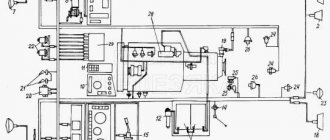
The power steering (power steering) Maz-5551, 5549, Maz-5335, 5336, 5337 (Fig. 33) is a unit consisting of a distributor and a power cylinder assembly. The power steering hydraulic system includes an NSh-10 gear pump installed on the car engine, an oil tank and pipelines.
Rice. 33. Power steering Maz-5551, 5549, Maz-5335, 5336, 5337 1 - power cylinder; 2 — rod; 3 - discharge pipeline; 4 - piston; 5 - plug; 6 — ball joint housing; 7 — adjusting nut for the backlash of the ball joint of the longitudinal rod; 8 — pusher; 9 — ball pin of longitudinal thrust; 10 — ball pin of the steering bipod; 11 - drain pipeline; 12 - cover; 13 — distributor housing; 14 - flange; 15 — pipeline to the above-piston cavity of the power cylinder; 16 — seal fastening clamp; 17 — pipeline to the piston cavity of the power cylinder; 18 — oiler; 19 — pins for fixing crackers; 20 — locking screw; 21 — power cylinder cover; 22 - screw; 23 — inner washer for securing the cover; 24 — rod head; 25 — cotter pin; 26 — drain line fitting; 27 — discharge line fitting; 28 — hose holder; 29 — adjusting plug for the play of the ball joint of the steering arm; 30 - spool; 31 - plug; 32 — spool plug; 33 - coupling bolt; 34 — connecting channel; 35 - check valve; 36 - glass. The power steering distributor Maz-5551, 5549, Maz-5335, 5336, 5337 consists of a housing 13 and a spool 30. The spool journals are sealed with rubber O-rings - one directly in the housing, the other in a plug 32 inserted into the housing and closed with a cover 12. The inner surface of the spool body has three annular grooves. The outermost of them are connected by a channel to each other and to the discharge line of the pump, the middle one is connected through the drain line to the pump reservoir. On the surface of the spool there are two annular grooves connected by connecting channels 34 with closed volumes called reaction chambers. The spool body is attached to the flange of the housing 6 of the power steering joints Maz-5551, 5549, Maz-5335, 5336, 5337. In the housing 6 there are two ball pins - 10, to which the steering bipod is attached, and 9, connected to the longitudinal steering rod. Both fingers are clamped between the spherical crackers by the plug 29 and the adjusting nut 7 by means of springs. Tightening of the crackers is limited by pushers 8. The hinges are protected from dirt getting inside by rubber seals secured to the casing with clamps. The fingers, within certain limits, can rotate in the crackers, which are kept from rotating by pins 19 inserted into the grooves of the crackers. The steering bipod pin 10 is fixed in a glass 36, which can move in the housing 6 in the axial direction within 4 mm. This movement is limited by the collar of the cork 29, wrapped in the glass. The shoulder in its extreme positions rests against the end of the distributor housing 13 and against the end of the housing 6 of the ball joints. Together with the glass 36, the spool 30 also moves, since it is rigidly connected to it using a bolt and nut. The power cylinder 1 is connected to the other end of the hinge housing 6 using a threaded connection and is locked with a nut. A piston 4 moves in the cylinder, connected by a nut to a rod 2. The piston is sealed with two cast iron rings. The cylinder cavity is closed on one side by a plug 5, sealed with a rubber ring, on the other - by a cover 21, sealed by the same ring and locked with a retaining ring and a washer, to which the cover is bolted. The rod is sealed in the cover with a rubber ring protected by a wiper. The outer part of the rod is protected from contamination by a rubber corrugated cover. At the end of the rod, a head 24 is attached using a threaded connection, in which rubber and steel bushings are placed. The rubber bushing is locked at the ends by the collar of the steel bushing and the nut. The cavity of the power steering cylinder Maz-5551, 5549, Maz-5335, 5336, 5337 is divided by the piston into two parts: sub-piston and supra-piston. These cavities are connected by pipelines 15 and 17 with channels in the distributor housing, which end with channels opening into the housing cavity between the annular grooves. The sub-piston and supra-piston cavities of the power cylinder can be connected to each other through a check valve 35, consisting of a ball and a spring, pressed by a plug. The Maz-5551, 5549, Maz-5335, 5336, 5337 power steering operates as follows: When the car engine is running, the power steering pump continuously supplies oil to the power steering 14 (Fig. 34), which, depending on the direction of movement of the car, either returns to the reservoir 10 , or is supplied to one of the working cavities (A or B) of the power cylinder 8 through pipelines 5 and 6. The other cavity is connected through the drain line 12 to the tank 10. Oil pressure through channels 3 in spool 2 is always transmitted to the reaction chambers 1 and tends to set the spool in a neutral position with respect to the body. When the car Maz-5551, 5549, Maz-5335, 5336, 5337 moves in a straight line (Fig. 34, a), oil is supplied by the power steering pump through the injection hose 13 into the outer annular cavities 20 of the distributor, and from there through the gaps between the edges of the grooves of the spool and the housing - into the middle annular cavity 21 and then along the drain line 12 into the tank 10. When the steering wheel is turned to the left (Fig. 34, b) and to the right (Fig. 34, c), the steering bipod 19 moves the spool through the ball pin 18 away from the neutral position . In this case, the discharge 20 and drain 21 cavities in the spool body are separated and the liquid begins to flow into the corresponding cavity of the power cylinder, moving the cylinder 8 relative to the piston 7 mounted on the rod 15. The movement of the cylinder is transmitted to the steered wheels through the ball pin 17 and the associated longitudinal steering rod 16. If you stop rotating the steering wheel 9, the spool stops, and the body slides over it, moving to the neutral position. The oil begins to drain into the tank and the wheels stop turning. Power steering Maz-5551, 5549, Maz-5335, 5336, 5337 has high sensitivity. To turn the wheels of the car, it is necessary to move the spool by 0.4-0.6 mm. As the resistance to wheel turning increases, the oil pressure in the working cavity of the power cylinder also increases. This pressure is transmitted to the reaction chambers and tends to set the spool to the neutral position.
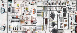
Rice. 34. Diagram of operation of the power steering Maz-5551, 5549, Maz-5335, 5336, 5337 1 - reaction chamber; 2 - spool; 3 — channels; 4 — distributor housing; 5 and 6 - pipelines; 7 - piston; 8 — power cylinder; 9 — steering wheel; 10 - tank; 11 - pump; 12 - drain line; 13 — discharge hose; 14 — hydraulic booster; 15 — piston rod; 16 — longitudinal steering rod; 17 and 18 — ball pins; 19 — steering bipod; 20 - discharge cavity; 21 - drain cavity; 22 - check valve.
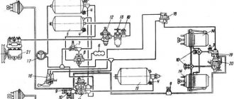
Rice. 35. Power steering pump Maz-5551, 5549, Maz-5335, 5336, 5337 a - pump; b - tension device; 1 — right bushing; 2 — driven gear; 3 - sealing ring; 4 - retaining ring; 5 - support ring; 6 - cuff; 7 - cover; 8 - sealing ring; 9 - drive gear; 10 — left bushing; 11 — pump housing; 12 — fixed bracket; 13 - axis; 14 - pulley; 15 — adjusting screw; 16 — lock nut; 17 — fork; 18 - finger. Due to the reinforcing effect of the hydraulic booster, the force on the steering wheel at the beginning of turning the wheels does not exceed 5 kg, and the maximum force is about 20 kg. The power steering system of Maz-5551, 5549, Maz-5335, 5336, 5337 has a safety valve installed on the power cylinder. The valve is adjusted at the factory to a pressure in the system of 80-90 kg/cm2. Adjusting the valve in motor vehicles is prohibited. It should be borne in mind that only short-term operation of the steering is allowed when the power is not working, since this significantly increases the force on the steering wheel and increases its free play. The speed of the vehicle with the amplifier not working should not exceed 20 km/h. The power steering pump of the Maz-5551, 5549, Maz-5335, 5336, 5337 gear type NSh-10 (Fig. 35) is installed on the left side of the engine and is driven from the engine crankshaft via a V-belt. The working fluid reservoir is installed on the radiator frame. Maintenance of the Maz-5551, 5549, Maz-5335, 5336, 533 hydraulic booster 7 When operating Maz-5551, 5549, Maz-5335, 5336, 5337 vehicles, systematically check the fastening of the hydraulic booster to the vehicle frame bracket, the fastening of the power steering pump pulley and periodically tighten the nuts distributor ball pins. At each maintenance check the tension of the pump drive belt. The belt tension is adjusted using screw 15 (Fig. 35, b). With the correct tension, the deflection in the middle part of the belt under a force of 4 kg should be within 10-15 mm. After adjustment, lock the screw with nut 16. Regularly, within the time period specified in the lubrication chart, check the oil level in the power steering pump reservoir, change the oil in the power steering system and wash the reservoir filter. Check the tightness of connections and seals of the hydraulic booster, pump, pipelines and hoses of the system daily. For the power steering system of Maz-5551, 5549, Maz-5335, 5336, 5337, use only clean filtered oil specified in the lubrication card. Pour oil into the pump reservoir 10-15 mm below the upper edge of the reservoir through a funnel with a double fine mesh. When pouring oil, do not shake or stir it in the container. The use of contaminated oil causes rapid wear of parts of the pump, distributor and power cylinder of the hydraulic booster. When checking the oil level in the pump reservoir during each maintenance (TO-1), the front wheels of the vehicle must be installed straight. At each maintenance-2, remove the filter from the tank and rinse. If the filter is significantly clogged with hardened deposits, wash it with a solvent used for painting cars. Before removing the filter, thoroughly clean the tank lid from dirt. When changing the oil, which is carried out 2 times a year (during seasonal maintenance), raise the front axle of the car so that the wheels do not touch the ground. To drain oil from the steering system of Maz-5551, 5549, Maz-5335, 5336, 5337, you must: - disconnect the reservoir and, removing the cover, drain the oil; — disconnect the discharge and drain pipelines from the distributor and drain the oil from the pump through them; — slowly turning the steering wheel left and right until it stops, drain the oil from the power cylinder. After draining the oil, rinse the power steering reservoir Maz-5551, 5549, Maz-5335, 5336, 5337, for which: - remove the filter from the reservoir, rinse it as indicated above; — thoroughly wipe the inside of the tank, removing any remaining contaminated oil from it; — install the washed filter in the tank; — pour fresh oil into the tank through a funnel with a double fine mesh and wait until it drains through the pipelines. When adding fresh oil, ensure that all air is removed from the system. To do this, you need to: - add oil to the tank to the required level and do not touch the system for about two minutes; — start the engine and let it run at low speed for two minutes; — slowly turn the steering wheel 2 times all the way to the right and left until the release of air bubbles in the tank stops. If necessary, add oil to the level indicated above; Reinstall the tank cover and its fastening parts; — turn the wheels to the right and left, checking for ease of control and the absence of oil leaks. Check the clearances in the ball pins with the engine running at each maintenance service - 1 by sharply turning the steering wheel to the right and left. There should be no play in the steering rod joint. In the steering bipod hinge, when the engine is not running, the play should be no more than 4 mm, and when the engine is running, up to 2 mm. Adjustments and repairs of the Maz-5551, 5549, Maz-5335, 5336, 5337 hydraulic booster Adjustment of the gaps in the ball pins of the Maz-5551, 5549, Maz-5335, 5336, 5337 hydraulic booster The appearance of gaps in the ball pins significantly affects the overall steering play. Most often, the gap increases in ball pin 9 (see Fig. 33), to which the longitudinal rod is connected, since much more force is transmitted through this ball pin than through the ball pin of the steering bipod. To adjust the gaps in the ball pins, partially disassemble the hydraulic booster. Therefore, it is best to perform adjustments on the hydraulic booster removed from the car. Adjusting the gap in the longitudinal link joint Maz-5551, 5549, Maz-5335, 5336, 5337: - remove the pipelines; — clamp the hydraulic booster in a vice and loosen the lock nut securing the cylinder; — unscrew the hinge body from the cylinder; — secure the hinge body in a vice, loosen the locking screw in nut 7 (see Fig. 33); — screw nut 7 until it stops, then tighten the locking screw securely; — assemble the ball pin housing with the cylinder. Tighten fully and unscrew until the pipes can be connected. Adjusting the clearance in the steering arm joint of Maz-5551, 5549, Maz-5335, 5336, 5337: - secure the power steering in a vice; — remove the distributor cover 12, undo the cotter pin and unscrew the nut; — unscrew the bolts securing the spool body and remove the body together with the spool; — unscrew the locking screw of the plug 29; — screw the plug 29 until it stops and turn it back until the hole for the locking screw coincides with the nearest slot in the glass 36; - tighten the locking screw until it stops; — install and secure the spool body; — insert the spool into the housing socket, install plug 32 of the spool, tighten the nut until it stops, unscrew it 1/12 of a turn and secure it with a cotter pin; — install and secure cover 12 and pipelines; — install the hydraulic booster on the car. Removing the hydraulic booster from a Maz-5551, 5549, Maz-5335, 5336, 5337 car. To remove it you must: - disconnect the pressure and drain hoses from the hydraulic booster; - Unscrew the nut of the coupling bolt securing the pin of the power steering rod head and knock the bolt out of the bracket; — knock out the pin securing the power steering rod head; — unscrew and unscrew the nuts securing the power steering to the steering bipod and longitudinal rod of the Maz-5551, 5549, Maz-5335, 5336, 5337; — using a drift, knock out the fingers from the holes of the steering bipod and the end of the longitudinal rod. Remove the hydraulic booster.
The procedure for disassembling power steering Maz-5551, 5549, Maz-5335, 5336, 5337 is as follows:
— remove pipelines and fittings; — unscrew the threaded connection between the rod head and the rod and unscrew the head. Remove the outer mounting washer; cover; — when the rubber bushing wears out, disassemble the head by unscrewing the nut and pressing out the steel bushing, and then the rubber bushing; — remove the cover fastening clamp, the cover and the inner washer of its fastening; — unscrew the bolts securing the power steering cylinder cover Maz-5551, 5549, Maz-5335, 5336, 5337, remove the washer, remove the retaining ring, sliding the cylinder cover back, remove the cover; — remove the piston with the rod and disassemble it; — unscrew the locknut securing the cylinder and unscrew the cylinder; — remove the clamps securing the power steering ball pin seals Maz-5551, 5549, Maz-5335, 5336, 5337 and the seals themselves; — unscrew the locking screw, unscrew the adjusting nut 7 (see Fig. 94), remove the pusher 8, spring, crackers and ball pin 9; — unscrew the cover bolts 12 and remove the cover; Unscrew the nut securing the spool and unscrew it, remove plug 32; — unscrew the bolts securing the spool body, remove the body, remove the spool; — unscrew the locking screw, unscrew plug 29, remove the bolt, pusher 8, spring, crackers and pin 10; — remove glass 36; — unscrew the check valve plug 35 and remove the spring and. ball. After disassembling the parts of the Maz-5551, 5549, Maz-5335, 5336, 5337 hydraulic booster, carefully inspect them. Scores and nicks are not allowed on the surfaces of the spool, the ball pin cup of the steering bipod and their bodies. There should be no marks or excessive wear on the working surfaces of the ball pins and crackers, and no noticeable damage or wear on the rubber rings. If the specified damage is detected, replace these parts with new ones. The Maz-5551, 5549, Maz-5335, 5336, 5337 hydraulic booster is assembled in the reverse order of disassembly. Before assembly, the rubbing surfaces of the spool, glass and fingers; lubricate with a thin layer of grease and make sure that the spool and glass move freely in their housings. jamming. Adjust the clearance in the ball joints as described above. After assembly, lubricate the ball joints with grease through oiler 18. Install the hydraulic booster on the Maz-5551, 5549, Maz-5335, 5336, 5337 in the reverse order of removal. When installing the hydraulic booster, tighten the pin fastening nuts securely and carefully secure them with cotter pins.
_________________________________________________________________________
_________________________________________________________________________
_________________________________________________________________________
- Cardan shafts and power take-off Ural-4320
- Transmission gearbox Ural-4320
- Bridges Ural-4320
- Transfer case Ural-4320
- Steering Ural-4320
- Truck cranes and cranes based on trucks
_________________________________________________________________________
_________________________________________________________________________
- Cylinder block and cylinder head YaMZ-236 HE2, YaMZ-236 BE2
- Checking and adjusting YaMZ-236
- Power system and lubrication system YaMZ-236
- Driven and driven clutch discs YaMZ-236, 238
- Cooling and lubrication systems YaMZ-238
- Fuel injection pump YaMZ-238
_________________________________________________________________________
- Kamaz diesel engine
- Repair and adjustment of Kamaz power steering
- Kamaz-152 gearbox with divider
- Gearbox parts for Kamaz-5320 gearbox
- Kamaz transfer case and driveshafts
- Kamaz gearbox repair
- Clutch KamAZ-5320
- Construction of Kamaz-4310 drive axles
- Power steering MAZ-5551, 5549, 5335, 5336, 5337
- Front axle and steering rods MAZ-5551, 5549, 5335, 5336, 5337
- Clutch adjustment MAZ-5551, 5549, 5335, 5336, 5337
- Adjustment and repair of gearboxes MAZ-5551, 5549, 5335, 5336, 5337
- Repair and maintenance of the rear axle MAZ-5551, 5549, 5335, 5336, 5337
- Front axle parts and steering rods MAZ-5516, 5440
- Steering Maz-5516, 5440
- Details of driving axles Maz-5516, 5440
- Clutch device ZIL-130
- Repair of ZIL-130 gearbox
- Repair of rear axle ZIL-130
- Basic parts of the ZIL-130 engine
- Transfer case and power take-off ZIL-131
- Drive axles ZIL-131
- Steering ZIL-131
- Maintenance of ZIL-645 engine parts