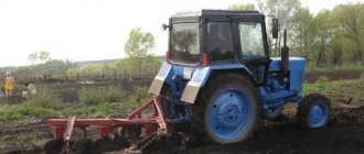
Plow design features
The PLN-3-35 is aggregated with tractors of the 1.4 kN class. These include the MTZ 80 and 82 tractors. A plow with angles or a skimmer is installed. If a vertical knife is mounted on the last body, then risky ones are no longer installed. The choice depends on the type of soil that needs to be processed and the condition of the tractor.
After purchase, it is necessary to assemble the following parts of the plow into a single structure:
- Frame;
- Frame;
- Support wheel;
- Coulter;
- Trailed part of the harrow;
- Hang it up.
When assembling and adjusting the plow, you must understand that the harrows and cleaning parts attached are its parts. The thrust wheel screw is necessary to regulate the depth of soil flash. The skimmer should be mounted depending on the depth of tillage. We recommend installing a skimmer on the MTZ 80 according to the following rules:
- Fixing the stands on the top hole corresponds to a flash depth of 20 cm;
- Posts in the second hole - plowing to a depth of 22 cm;
- Stand on the third hole - plowing depth 25 cm;
- Stand on the fourth hole - plowing depth 27 cm;
- The bottom hole corresponds to a flash at a depth of 30 cm.
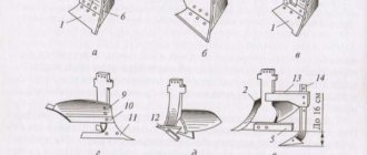
The plow body is assembled from shares that rotate to a solid stand. The blade and floorboard are also attached there. There are several types of plow body: cut-out, high-speed, moldless and classic with a deepening element.
The plow skimmer for the MTZ 80 tractor consists of a working part and a small body. A skimmer is used to remove plant residues. The skimmer structure consists of elements: blade, ploughshare, stand.
The wheel on the plow is necessary to regulate the depth of plowing. Refer to the directions above and the markings on the stand to set the depth correctly. The wheel consists of a disk with a rim, a bracket with a hub and an axle shaft.
The plow is connected to the tractor using a canopy. The harrow is attached to a special trailer.
Agrofak
Previously, the speed of plowing depended on the movement of the animal used for plowing. It usually did not exceed 3-4 km per hour. Plows and its working parts were adapted to it. With the transition to tractor traction, the shape of the blade and ploughshare remained without any significant changes, since the speed during tractor plowing increased slightly compared to horse-drawn plowing.
The first studies on the use of increased speeds for plowing were carried out near Moscow on soddy-podzolic soils in 1930 by P. A. Nekrasov, and somewhat later by P. E. Nikiforov, V. P. Nartsisov and others. It was found that with an increase in speed up to 7 km per hour and more, the soil crumbles more strongly, which helps to improve the structure of the arable layer, lumpiness, fluffiness, and ridges are reduced, the soil surface becomes smoother and crop residues are incorporated much better. In addition, with increasing plowing speed, the water-air regime of the soil improves and the content of nitrates in it increases due to increased activity of nitrifying bacteria. As a result, on clay and loamy soils, the yield of many agricultural crops increases by 12-18%. The transition to plowing at high speeds also makes it possible to increase the productivity of units by 20-40%.
V.P. Nartsissov found that on sod-podzolic silty-sandy soil, when the plowing speed with plows with skimmers increased to 1.6-2.2 m per second, the total porosity increased by 4.6% and the ratio of capillary porosity to total decreased. In addition, the microbiological regime of the soil improved (the positive effect lasted from 1.5 to 3 months), the plants developed better and produced a high yield.
Y. K. Dubovsky, V. S. Lopukhov et al. (1961) recommend using increased operating speeds on all tractors available on the farm. This especially applies to tractors of the MTZ brands of all modifications, T-28.
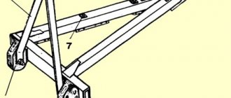
When the speed of soil cultivation exceeds 7 km per hour with plows with conventional moldboards, the quality of plowing decreases. This is due to the sudden throwing of the layer to the side, its disorderly placement and strong spraying of the soil. In order not to deteriorate the quality of plowing, mounted plows (PNS-3-30 and PN-4-35S) are produced, designed for cultivating the soil at high speeds (9 km per hour) and designed for attachment to MTZ and T-75 tractors. The industry is also creating new high-speed tractors and plow bodies for plowing at a speed of 12-15 km per hour. These plow bodies are distinguished by flatter shapes of the working surfaces and smaller angles of installation of the ploughshare to the wall and bottom of the furrow (Fig. 42).
According to the research of I.M. Nebolsin (1960), when the engine speed during pre-sowing cultivation of plowed land (heavy loamy leached chernozem) was increased from 6.2 to 9.5 km per hour, the degree of soil loosening remained almost unchanged. It was higher only when cultivating at a speed of 10 km per hour.
Processing at high speeds should be carried out in fields that are free of stones, without steep slopes, ditches, ditches and other obstacles. Thus, to expand the use of plowing at higher speeds, it is necessary to improve the condition of the fields. Before plowing, ditches and depressions must be leveled, stones, bushes and other obstacles that impede field work must be removed from the fields.
The quality of plowing should not be allowed to decrease by increasing its speed. When plowing, it is necessary to maintain straightness. There should be no blemishes, blocks, deep furrows, high ridges or incomplete coverage of stubble and weeds. Currently, there is enormous interest in production not only in plowing at higher speeds, but also in increasing the speed of machines and implements in other methods of tillage and sowing crop seeds.
| < Previous | Next > |
Safety precautions before setup and assembly
You cannot start assembling and setting up a plow for a tractor without knowing the safety rules. They include the following items:
- Before the tractor starts moving, you must sound a sound signal. Only then do they begin to move smoothly.
- Before raising and lowering the plow, you must make sure that there are no animals or people nearby.
- It is forbidden to engage infantry if there is any malfunction of the plow.
- Stand near a working plow.
- If the restrictive chain system of the plow is weakened, turns cannot be made.
- Do not sit or stand on the frame of the equipment while moving.
- With the tractor running, adjust, adjust or tighten fasteners on the equipment.
- Remove soil and plant debris from the plow during operation, without turning off the equipment.
- The plow cannot be adjusted without additional support.
- Before transporting the plow, it must be raised and the limit chains tightened as much as possible.
- If the fasteners are not tightened enough, you cannot start flashing.
Preparing and setting up the plow for work
The plow is assembled on a special supporting wooden block or beam with a cross-section of 65 or 70 cm. The plow is heavy and if the structure falls, it can kill the tractor driver.
Assembly work is carried out in the following stages:
- Open the packaging and select spare parts; they should be put aside. We lay out the main components in a convenient order.
- We bring the frame into locking mode and install it on the prepared stand.
- The housing is hung and inserted into the stiffening beam and the rack with a bolt. The housing stand is mounted to the frame using locknuts.
- On the left, the skimmers are screwed to the body in front of the body holders using brackets. There is no need to tighten the staples at this stage.
- We secure the support wheels using brackets and spring washers. They are attached to the outside of the structure.
- The support wheels are lowered all the way; to do this, turn the screw nut at the end counterclockwise).
- We tighten all the brackets until they stop and remove the plow from the stand.
- The scraper is mounted to the wheel bracket using washers and nuts.
- The hitch is mounted on the plow frame using bolts, which must be tightened until they stop.
- We screw red reflectors to the back of the main beam.
The plow is assembled and ready to be set up. The tincture is carried out in the following steps:
- Before using for the first time, inspect the equipment. Lubricate the wheel bearings and all rubbing parts with grease.
- Set the skimmer to the required plowing depth. The gap between the coulter shares and the body must be at least 250 mm. Using the protrusion on the holder, we adjust the depth of tillage.
- Tighten the skimmer clamps completely. In this case, the field edge of the skimmer covers the edge of the body.
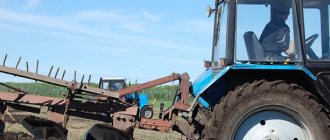
- The PLN plow has a soil grip of 105 cm, so the track should be 1560 mm. To prevent shortfalls when plowing, the right wheel of the machine is placed in the furrow.
- The slanting rods of the mounted part are adjusted after the plow is installed on the ground.
- The braces are placed in the front holes of the rod.
- Before work, it is necessary to adjust the limit chain. The longitudinal rods should swing freely horizontally by 120-130 mm in different directions. To do this, the chain is built with a slight slack.
- Before plowing, it is necessary to adjust the depth by adjusting the traction of the mounted part and the support wheel. Initially, according to the timing of the front wheel, the average depth value is set and the first row is passed. Next, the flash depth is adjusted for each type of soil individually.
- When working, the right side of the frame should always be slightly higher than the left. As the furrow passes, it will break out and be strictly parallel to the soil.
- After passing the furrow, make sure that the plowing is uniform and completely covers the plant residues. There is an adjustment on the left side of the plow that will help make the plow for the MTZ 80 tractor more stable. If the plow moves to the side, then the canopy is moved back.
- If the frame warps, then you need to lengthen the brace.
- You can adjust the plowing depth of the front part of the body using the right link slants from the mounted unit, the rear part using the top one. In this case, the support wheel is placed at the required plowing depth and the position is fixed using a support bolt in the holder.
High-quality plowing can be determined by several criteria:
- The plowing depth of all plow bodies is uniform, the furrows are the same.
- When plowing forever, the adjusted units remain in the same position.
After moving to new fields, with a different type of soil, the plow must be adjusted in a new way.
Adjustments of the rear linkage MTZ-82.1/80.1
_____________________________________________________________________________
_____________________________________________________________________________
____________________________________________________________________________________________
Brace On the MTZ-82.1/80.1 Belarus tractor, two types of braces can be installed: screw and gear. Upon request, one of three complete sets of a pair of braces can be installed: - two gear braces; — one gear brace (on the right side along the tractor) and one screw brace; - two screw braces. Fig. 105. Screw brace 1 – screw with hinge; 2 – screed; 3 – lock nut; 4 – fork. Adjust the length of the screw brace of the hitch in the following sequence: - unscrew the lock nut 3; — rotating tie 2 clockwise or counterclockwise to change the length of the brace; — having adjusted the length of the brace, lock the screw connection with lock nut 3. The gear brace is shown in the figure. The length of the MTZ-82-1/80-1 Belarus brace is adjusted by rotating handle 5 clockwise or counterclockwise. Fig. 106. Gear brace 1 – handle; 2 – fork; 3 – pipe; 4 – body; 5 – earring. The length of the braces (both screw and gear) is adjustable from 425 to 520 mm. When shipped from the factory, the braces are adjusted to a length of 475 mm. To speed up the change in the length of the braces, two holes are provided on their fork for installing a pin. To copy the topography of the cultivated area of the field when working with wide-cut machines and to avoid damage to the braces, connect the braces to the lower links through grooves. The grooves of the brace fork should be behind the hole along the tractor to avoid damage to the brace. When working with agricultural implements, adjust the length of the right brace to the working depth. Upper link The length of the upper link of the rear linkage MTZ-82.1/80.1 Belarus can be adjusted from 500 to 740 mm. Adjust the length of the upper link in the following sequence: - unscrew locknut 4; — rotating handle 3 of pipe 2 clockwise or counterclockwise to change the length of the upper rod; — having adjusted the length of the rod, lock the screw connection with lock nut 4. To attach the upper link to the implement, use pin 6 of the rear hinge; to fix the pin, install a pin with ring 7 on it. Fig. 107. Upper link 1 – front screw with hinge; 2 – pipe; 3 – handle; 4 – lock nut, 5 – rear hinge screw; 6 – finger; 7 – pin with ring. On MTZ-82-1/80-1 Belarus tractors with a power regulator, linkage 1 is installed. Depending on the type of work performed, the following options for installing the upper link 2 into the holes of linkage 1 are recommended: - when using the rear linkage in power control mode, the upper linkage of the linkage install the devices on the two upper holes of the earring (positions “A” and “B”); — when using the rear linkage in positional control mode, install the upper link of the linkage on the upper hole of the linkage (position “A”); — when using the hitch in the height adjustment mode, install the upper link of the hitch on the lower hole of the shackle (position “B”); — when performing transport work and work when the front end of the upper link is not connected to the machine or implement, install the upper link of the hitch on the lower hole of the shackle (position “B”). Lower links MTZ-82.1/80.1/82.2 Belarus tractors can be equipped with detachable standard, detachable shortened or telescopic lower links with hinges. Additional lower link axles are also installed, which can be used to perform certain types of work. When moving the front ends of the lower links from the main axles to the additional axles of the lower links, it is necessary to re-adjust the lengths of the braces and locking ties in the transport and working position. Installation of detachable shortened lower links with a length of 805 mm increases the lifting capacity of the RHL by approximately 10% while simultaneously reducing the lifting height by approximately 10%. An additional point is provided at the front ends of the split lower links. When attaching the brace to the additional point “A”, the load capacity of the RHL increases by approximately 10%. Installing the cross member and rear ends of detachable lower links in the working position MTZ-82-1/80-1 Belarus tractors with detachable lower links are equipped with a cross member (TSU-1Zh) and rear ends of lower links, as shown in view a. To install the cross member in the working position (as shown in view b, perform the following operations: - unsplint and remove the eyes 3, remove the cross member 4; - unsplint and remove the pins 2, remove the rear ends of the lower links 5; - install the cross member 4 on the front ends of the lower links 1, as shown in view b, secure it using the eyes 3, pins 2 and cotter pins; - connect the limiting ties 6 to the eyes 3. Fig. 108. Installing the cross member in the working position 1 - front ends of the lower links; 2 - pin; 3 – eye; 4 – cross member; 5 – rear ends of the lower links; 6 – limit tie. To install the rear ends of the lower links 5, dismantle the cross member 4, using the eyes 3, pins 2 and cotter pins to the front ends of the lower links 1, attach the rear ends of the lower links of the rods, connect the 3 limiting couplers 6 to the eyes. When operating the tractor using the towing hitch device (TSU-1Zh), the couplers must be completely locked in the working position. To do this, it is necessary to install the lower links together with the cross member 4 in a horizontal position and perform full blocking couplers in the working position, as set out in paragraph Telescopic lower links and double cross member. Upon request, the MTZ-82.1/80.1 Belarus tractor can be equipped with a reinforced ZNU with telescopic lower links, which are installed on an axle with a diameter of 35 mm instead of a 32 mm axle. If necessary, the length of the telescopic rods can be adjusted stepwise within ± 80 mm from the middle position (the resulting rod lengths are 805 mm, 885 mm, 965 mm), and the load capacity of the hitch will change (805 mm is the highest load capacity, 965 mm is the lowest load capacity ). To set the required length of the lower link, do the following: - unscrew nut 3 and remove eye 2; — move the rear end 4 of the telescopic rod to the required position, install the eye in the corresponding hole and tighten the nut; — set the required length of the second rod in the same way. Eyelets 2 should only be installed on those holes as shown in the figure. Fig. 109. Installing a double crossbar on telescopic rods 1 – front end of the telescopic rod; 2 – eye; 3 – nut; 4 – rear end of the telescopic rod; 5 – tip of the double crossbar; 6 – double crossbar; 7 – kingpin. To work with trailed agricultural machines, a double crossbar TSU-1Zh-01 6 with a kingpin 7 is supplied to order with telescopic lower links. In this case, its tips 5 are installed instead of the rear ends of the links 4 (the eye is installed on the middle holes of the tips 5 of the double crossbar). The distance from the PTO end to the kingpin (coupling point) in this configuration will be equal to 470 mm. If necessary, this distance can be adjusted in steps within ± 80 mm from the average position by changing the length of the telescopic rods.
_____________________________________________________________________________
__________________________________________________________________________
Service and adjustments MTZ-82
- Controls and instruments
- Working with agricultural machinery
- Maintenance of diesel engine D-243
- Clutch adjustments
- Steering
- Tractor brakes Belarus
- PTO power take-off shaft
- Front axle
- Front drive axle repair
- Hydraulic system and rear linkage
- Electrical equipment
- Maintenance
__________________________________________________________________________
Operation and service MTZ-82.1, 80.1, 80.2, 82.2
- Controls and instruments
- Gearbox and PTO control
- Rear linkage control
- Cabin elements
- Electrical components
- Clutch
- Transmission
- Gearbox and creeper control
- Reverse gearbox
- Rear axle of Belarus tractor
- Rear axle differential lock
- Rear power take-off shaft
- Tractor brakes Belarus
- Pneumatic system
- FDA with bevel wheel reducers
- FDA with planetary helical wheel reducers
- FDA drive
- Chassis system
- Hydrostatic steering
- Power steering
- Hydraulic linkage system
- Rear linkage adjustments
- Cabin Belarus
- Maintenance
- Engine Maintenance
- Transmission Maintenance
- Front drive maintenance service
- Hydraulic and steering maintenance
- Front Axle Maintenance
- Maintenance of the pneumatic system and brakes
Repair of MTZ-80
- Cylinder head repair
- Repair of piston group D-240
- Repair of fuel equipment
- Starting motor repair
- Steering repair
- Front axle repair
- Clutch and reduction gear repair
- Transmission repair
- Rear axle repair
- PTO repair
- Rear linkage hydraulic system repair
- Electrical equipment repair
Maintenance and operation of MTZ-1221
- Controls and instruments
- Transmission
- Clutch
- D-260 engine maintenance
- Rear axle
- Service brakes
- Pneumatic equipment
- PTO
- Front drive axle
- Mounted hydraulic system
- Electronic rear linkage control
- Rear linkage
- Steering
Maintenance and operation of MTZ-320
- Controls and instruments
- Diesel engine
- Clutch and gearbox
- Rear axle
- Brakes
- Rear power take-off shaft
- Front drive axle
- Steering
- Hitch and hitch
- Hydraulic system
- Electrical equipment
- Aggregation
Operation and service of tractors
- Block crankcase and crank mechanism
- Gas distribution mechanism
- Diesel engine power supply system
- Tractor engine control system
- Tractor engine cooling system
- Diesel starting system
- Tractor power transmissions
- Tractor transmission T-150, T-150K
- Drive axles of wheeled and tracked tractors
- Tractor chassis and control
- Chassis and steering of wheeled tractors
Rules for plowing with an adjusted plow
For uniform and correct plowing, a number of rules must be followed:
- When moving from one furrow to another, the plow rises to the transport position.
- Circular plowing can only be done with a reversible plow.
- The plow turns smoothly.
- When transporting the working body, it is necessary to control the ground clearance. The distance from the road to the plow must be constant.
- When using a power deepener, the support wheel is removed from the plow. The depth is adjusted automatically.
- When plowing with power control, remove the support wheel from the plow. In this case, the specified plowing depth is maintained automatically using a power regulator.
Share