Vkontakte community
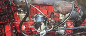
Pavlov Vladimir. Checking the pressure in the hydraulics of the MTZ tractor.
T with NS
What can be useful for this and what will you have to buy in addition? DT repair
This video shows how to remove the NSh drive gear on a MTZ tractor. Published April 24,
Now only idle speed. According to the pump marking.
If you have any questions, please contact us, we will answer everyone.
Ja View profile. Replacement of the cuff seal and disassembly of the hydraulic valve Modification of the hydraulic distributor drain line
We recommend: front axle MTZ-82 device diagram
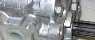
Drive of the NSh-32U oil pump of the T-40 and T-40A tractor
Gear (9) [fig. 1] of the drive is constantly engaged with the intermediate timing gear of the internal combustion engine. The gear (9) rotates in a pair of ball bearings, which are pressed onto the cantilever axle (11), secured in the hole in the front sheet of the internal combustion engine by means of a nut (10).
Rice. 1. Drive of the NSh-32U oil pump of the T-40 and T-40A tractor.
1) – Lever lock pin;
2) – Pump activation lever;
9) – Pump drive gear;
to the timing gear cover houses a hydraulic pump shut-off mechanism, which is made in the form of a ball clutch.
The long gear hub (9), equipped with four radial holes in which steel balls (13) are located, is the driving part of the ball clutch.
The driven bushing (8) is loosely seated in the hub bore and is secured against axial displacement by means of a spring retaining ring (7). The bushing (8) has four holes along its outer diameter, located opposite the balls, and along its inner diameter there are slots.
is engaged and disengaged by moving the race (14) along the outer surface of the gear. When turned on (movement towards the gear), the cage will press on the balls and push them into the holes of the sleeve. Torque is transmitted through the balls from the hub to the bushing and then through a splined connection to the drive gear of the oil pump, which is attached to the drive housing (5). To turn it off, you need to move the cage in the opposite direction, in which case the balls will separate and the clutch will disconnect.
to move the coupling. The end of the fork roller (3), removed from the body, is equipped with a lever (2) with a spring lock. The lock pin (1) fits into one of a pair of holes on the drive body and fixes the position of the lever.
between the lever and the shaft is keyless, as a result of which by loosening the terminal and moving the lever, you can find a position that corresponds to the normal disengagement and activation of the clutch.
If the position of the lever is incorrect in relation to the roller, it is possible that the stroke of the fork and cage may increase when turned off, which results in the balls falling out.
Switching the clutch on and off is allowed not only when the engine is stopped, but also when the engine is running at low speeds.
The shaft, rather than spherical, shape of the ball holes on the driven bushing is designed for engagement on the move.
During operation of the T-40 (T-40A) tractor, the NSh-32U pump is constantly turned on.
turned off when working on a stationary basis or during winter engine start-up.
Lubricating all parts of the pump drive is carried out by spraying oil onto the engine timing gears.
Source
Steering pump dispenser NSh 10 for tractor MTZ 82
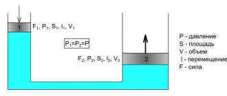
The hydraulics of the steering system of the MTZ 82 tractor uses a gear oil metering pump NSh 10 of left rotation. The pump volumetric flow is 20 liters per minute at 2200 rpm.
Device
The metering pump consists of a cover, a housing and a pumping unit, the device of which includes a driven and driving gear, two shaped cuffs, two bearings and a plate. Bearings act as supports for gear journals and for sealing the end surfaces of gears. The external features of the bearings are shaped like the number 8. Each bearing has two bores for the gear journals. Shaped cuffs placed in grooves on the opposite side of the gears limit the low pressure zone from the high pressure zone. To seal the joint between the cover and the body, an O-ring is used, which is placed in an oval bore on the body.
Steering dispenser MTZ 82: 1 - cover; 2 - sealing ring; 3 - bearing; 4 — body; 5 - drive gear; 6 and 8 — cuffs; 7 — driven gear; 9 - plate.
The drive end of the drive gear is sealed by two frame cuffs, which prevent oil from flowing from the hydraulic booster into the diesel crankcase.
To reduce the flow of oil through the gaps between the ends of the bearings and gears, the dispenser pump nsh 10 is equipped with automatic pressure of the bearings to the ends of the gears using pressure that is supplied from the discharge zone into the cavities limited by the shaped cuffs. Since the area of this zone exceeds the area of the high pressure zone acting from the gear teeth on the bearings, the latter are pressed towards the ends of the gears with a force that is much higher than the force of their pressing from the gear teeth. Due to this, the bearings are constantly pressed against the ends of the gears, as a result of which gaps between the ends of the gears and the bearings are not allowed.
To lubricate the gear journals, oil is used, which is supplied to the spiral grooves in the bearing bores from the suction cavity. This oil also cools and lubricates the gear journals, after which it goes back into the suction cavity.
Technical characteristics of the NSh-10 dispenser steering pump for the MTZ 82 tractor
| Type | gear |
| Pump flow, l/min | 21 |
| Pressure limited by the safety valve, MPa (kgf/cm²) | 9 (90) |
| Rotation speed, rpm | 2200 |
| Shaft rotation | left |
| Working volume, cm³ | 10 |
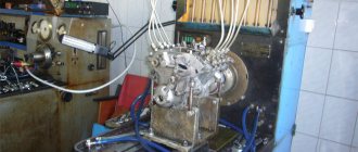
Device, diagrams, repair
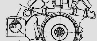
Hydraulics of the T-40 tractor: diagram and malfunctions
The hydraulics of the T-40 tractor are divided into a power steering system and a separate hydraulic mounted system. These systems operate from one pump, but have different purposes. The hydraulic linkage system is used to operate the tractor with trailed, semi-mounted, mounted implements and machines. The power steering system is designed to reduce the force applied to the steering wheel.
Device and circuit
The T-40 hydraulic system consists of a gear pump, a hydraulic tank with a filter, a flow division valve, a hydraulic distributor, a hydraulic booster, shut-off devices, pipelines and hoses, remote and main hydraulic cylinders, and breakaway couplings.
T-40 hydraulic diagram: 1 - hydraulic tank; 2 - pump; 3 — flow division valve; 4 - spool; 5 — spool spring; 6 - filter; 7 — power steering; 8 — hydraulic distributor; 9 — main hydraulic cylinder; 10 — remote hydraulic cylinders.
Operating principle
Oil from the hydraulic tank is supplied to a gear pump, which forces it into the distribution valve. The valve divides the oil flow into two branches: one goes to the hydraulic booster, and the second goes to the hydraulic distributor of the hydraulic lifting system. The hydraulic distributor supplies a flow of oil either to the hydraulic tank through the oil return line, or to the hydraulic cylinder, or through the rear and side outlets directly to the hydraulic drive of agricultural equipment.
Hydraulic system malfunctions
What to do if the T-40 hydraulics do not work?
The attachment does not rise to transport position:
1. Jamming of the distributor bypass valve - disassemble and wash the bypass valve.
2. Safety valve contaminated - Disassemble and clean the valve assembly. Adjust it to a pressure of 130-140 kgf/cm².
The implement rises too slowly or jerkily:
1. There is not enough oil in the hydraulic tank - add oil to the top mark on the dipstick.
2. Air leak in the suction line - tighten the suction line connections.
3. Air leakage through the oil seal of the pump drive gear - the oil seal must be replaced.
4. Increased leakage in the pump - the pump should be replaced.
The distributor handles do not automatically return to the neutral position from the working position:
1. The safety valve spring is weak - adjust the safety valve.
2. The distributor spool booster spring is too tight - it is necessary to adjust the response pressure to 100-125 kgf/cm².
Related videos
Gear pump rotation change. Additional pulley from the GAS pump. The maximum pressure for which the pump is designed for continuous operation. Hi Rom, well, that’s what I’m afraid of: if the valve on the tap is screwed on to low pressure, after installing a good pump, you won’t have to go to the “broken arrows” topic.
Good luck to the beginners! A hydraulic press is used to make briquettes from sawdust.
Lviv loader, Lvov loader, Lvov loader Torque, nominal.
Your city. Working volume, cm 3.
And also NS gear pumps come in right and left rotation, and single-section, two-section and three-section, the last two types are called tandem or paired NS. Replacement intervals, ask if you have questions!
Good luck to the beginners! MTZ from scrap metal 11 series. nsh 50 instead of nsh 32 on t40
General characteristics of the T-40
Purpose:
- plowing;
- processing of field crops;
- mowing;
- hay harvesting, baling;
- snow clearing;
- bulldozer and transport work.
Operational features:
- high cross-country ability;
- good maneuverability (thanks to the reverse transmission, all the functionality of the machine is available in reverse);
- adjustable track and clearance;
- two power take-off shafts;
- Various options for installing wheels depending on the specific purpose.
To publish messages, create an account or log in
On the channel you can not only watch... Sergey Afanasyevsky.
Pavlov Vladimir. How to determine the direction of rotation of a gear pump using the example of the NSh pump Removing the NSh - 50 Yuri Nepomnyashchiy. Can you tell me why? Dear Colleagues.
Nominal outlet pressure, MPa:. Removal of NS - 50 Yuri Nepomnyashchiy.
Log in registration. DT repair
Index 4 means atm. The sound of operation is exactly like in my MTZ with engine D
How to place your advertisement? Message 3. And then the topics appear - “the oil is heating up - why?
I’ll tell you and show you how I made an adapter plate for the NSh50 hydraulic pump for the Japanese Hino Ranger manipulator. Which pump is better nsh 32 or nsh Installing NSh-50 on T-40. My version