June 14, 2019
First, let's define what a pump is (hydraulic pump, hydraulic machine).
A pump is a hydraulic machine that converts the mechanical energy of a drive motor into the energy of fluid flow.
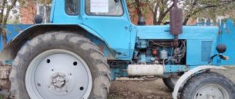
In simple terms, we can say the following: the rotational energy, whether from the flywheel or from the tractor PTO, is transmitted through the hydraulic pump shaft, where the suction line has a larger diameter hole and the outlet has a smaller one.
In this regard, pumps are structurally divided into right-hand and left-hand rotation. Their rotation can be determined in two simple ways, the first visually (by eye), the second by the alphanumeric designation on the device body. There are several more “handicraft” ways to determine the direction of rotation of the pump - this is by using a pressure gauge, and by using a cuff for NSh (gear type) pumps; we will not dwell on them in this article; if you are interested, you can google it.
Pump NSh 32A-3: design and principle of operation
The NSh 32A-3 pump is quite common and in demand in agriculture.
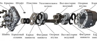
This mechanism carries out the flow of oil in the hydraulic system under pressure. As a result, a hydraulically powered organ is activated in an agricultural machine. The main components of the nsh gear pump are the housing (item 1), which is closed with a cover (item 3). A swinging unit is installed in the housing, which consists of a driven (item 2) and a drive (item 4) gear. The gears are placed in a bearing cage (pos. 15), plates. In the discharge zone, due to the oil pressure through the cuff (pos. 11), the holder (pos. 14) is continuously pressed. it is pressed by a sealing surface to the outer surfaces of the gear teeth.
When wear occurs on the surfaces of the teeth and race, the race moves toward the gears. As a result, there is a minimum gap between the surfaces of the teeth and the cage.
In the area of the cuffs (item 10), the plates are pressed against the gears under the pressure of the working fluid. The cuffs (item 9), installed in the recesses of the body (item 1) and the cover (item 3), create counterpressure zones to relieve the clamping holder (item 14) from the stresses that arise from the cuffs (item 10).
Thus, the design of the pump provides for hydraulic automatic pressing both along the end surfaces of the teeth and along the surface. And when the parts of the swing unit wear out, the gaps are sealed.
In order for the oscillating unit to rotate during operation of the NSh-32A-3 gear pump, there is a centering sleeve (item 5) pressed into a hole made in the hydraulic pump housing. The drive gear shaft (item 4) is sealed using two seals. One of the inner cuffs is mounted with a spring bracelet on the outside, and the other is mounted with a spring bracelet inside the body. The joint between the hydraulic pump housing and the cover is sealed with a ring (item 13).
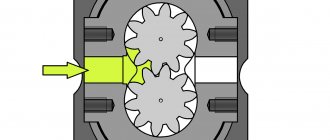
The operating principle of a gear pump is as follows.
Two gears of equal width, driving 1 and driven 2, are in mesh and located in housing 3 with minimal radial clearance. The side walls of the pump are adjacent to the end surfaces of the gears. When the gears rotate, the fluid filling the cavities between the teeth is transferred by the gears along the inner surface of the housing (shown by arrows) from the suction cavity A to the discharge cavity B.
The NSh 32A-3 pump is available in both right and left rotation. The Agro-Service company presents products from the Hydrosila plant, Kirovograd, which have excellent performance characteristics and a high degree of reliability.
Basic gear pump
Wear of the walls and bottom of the housing wells, the ends of the gears and the surfaces of the trunnions, the holes of the bushings under the trunnion, the chipping of the edges of the pump cover flanges under the sealing gland, wear of the cover plane.
Gear pump repair
The pump is disassembled and repaired if it has volumetric efficiency. less than 0.6 (after replacing seals). To properly monitor this indicator, it is necessary to distinguish between the designations of hydraulic pumps. In the markings NSh-10D, NSh-32 and NSh-46U, the figure corresponds to the theoretical performance of the new pump in cubic centimeters per gear revolution. The letters D, U after the number indicate the pump model. The direction of rotation of the drive gear is shown on the pump plate with the letter L (left) or R (right, but most often not indicated)
Gear pump housing dimensions, mm. Table 1
| Pump brand | Marking | D | D1 | D 2 | d1 | d2 | A | H | H1 |
| NSh-32U-L | New | 55+0,02 | 66+0,5 | 59+0,2 | 37+0,17 | 84+0,1 | 101 | ||
| P1* | 55,5+0,02 | 66+0,5 | 59,5+0,2 | 37+0,17 | 84,3+0,1 | 101 | |||
| P2* | 54,7+0,02 | 66+0,5 | 58,5+0,2 | 37+0,17 | 84,3+0,1 | 101 | |||
| P3* | 54,5+0,02 | 66+0,5 | 58,5+0,2 | 37+0,17 | 84,3+0,1 | 101 |
* Dimensions for crimp-reconditioned housings
When disassembling the pumps, unscrew the bolts, remove the pump cover and remove the parts manually. The puller is used only when removing the lower pair of bushings from the socket. The bushings of the cover and sealing ring of the NSh-32 and NSh-46 pumps are interchangeable, but if the pump is reassembled from these parts, then depersonalization of the bushings and gears is not allowed.
Pumps received for repair for the first time are repaired by displacing the gears with concentric bushings. This method allows you to repair the pump at a lower cost, since the restoration of the pump casing is reduced to one operation - boring the wells to an increased size (Table 1; Fig. 1). the pump is assembled with eccentric bushings; the displacement value of the gear axis should be equal to half the difference in the sizes of the gear tooth heads and the housing wells.
Fig.1. Hydraulic pump housing
With greater wear on the surfaces of the pump casing (second and third repairs), the casing is subjected to plastic deformation - hot compression.
Rice. 2. Device for crimping the pump housing: 1-repairable pump housing; 2-ejector; 3-matrix; 4-mold body; 5-puason; 6-top plate.
To do this, the body is placed in an electric heating oven with automatic temperature control and kept for 30 minutes. at 500+10 0 C. Then the body is installed in the matrix 3 (Fig. 2) of the device and compressed under a press. The compression of the housing must be completed at a temperature not lower than 4300 C. The compressed housing is subjected to heat treatment: heating and holding for 30 minutes. at 5200 C, quenching in water at a temperature of 60-1000 C and tempering (aging) for 4-6 hours at 170-1800 C. The compressed body is bored on a 1L62B lathe or on 6M82 and 6M12P milling machines using a device (Fig. 3).
Rice. 3. Device for boring housings of gear pumps: a - jig for pinless installation of the housing; b - device for boring; c-mandrel; 1-device body; 2-pin; 3-axis housing; 4-conductor body; 5-movable cone; 6-clamp; 7-cutting mandrel; 8-clamp screw; 9-incisor; 10-pin; 11-incisor.
The ellipse of the bored wells should be no more than 0.01 mm, the taper should be no more than 0.02 mm, the non-parallelism of the well axes should be no more than 0.03 mm, and the discrepancy between the planes of the bottoms of the body wells should be no more than 0.02 mm. The depth of the wells is controlled by an indicator.
To restore pump gears, the worn surfaces of the journals, the ends and surfaces of the heads of the gear teeth are ground to repair sizes on a 3B12 cylindrical grinding machine. A grinding wheel of the PP-300x40x127-Ek brand is used for grinding the ends of the gears, as shown in Figure 4. The radius of curvature of the edges of the teeth should be 0.01 mm.
Rice. 4. Grinding the ends of gears: a-position of the wheel edge during grinding; b-end grinding; c-filling the grinding wheel.
The runout of the ends of the gear teeth relative to the center line is allowed no more than 0.01 mm. The grinding wheel should be adjusted after processing 20-30 gears. The dimensions of the gears after grinding are shown in Table 2.
Dimensions of gear pump gears after grinding. table 2
| Pump brand | Marking | Outer diameter of gear tooth head, mm | Trunnion diameter, mm | Gear tooth length, mm |
| NSh-32U-L | New | |||
| P1 | ||||
| P2 | ||||
| P3 |
The depth of the cemented layer of the gear after processing must be at least 0.8 mm (hardness HRC 58-62).
Depending on the tooth length, the repaired gears of each repair size are sorted into groups with an interval of 0.005 mm using a lever bracket.
Pump bushings are repaired by plastic deformation by compression (Fig. 5) in a cold state.
Rice. 5. Device for crimping bushings: a-device for crimping bushings; b-bushing; 1-rod (working tool); 2-puason; 3-sleeve; 4-matrix; 5-liner; 6-ejector; 7-matrix body.
The dimensions of the bushing blank after compression are given in Table 3.
Dimensions of the bushing blank after compression Table 3
| Pump brand | D | D | A | L | L | B |
| NSh-32U-L | 57+0,1 | 24,8+0,1 | 23+0,1 | 44 | 17 | 10 |
The end B of the compressed bushing is machined, the oil groove is expanded to diameter d1 (Fig. 6), or the hole for the trunnion is bored to size d.
Rice. 6.
When machining, an eccentric collet chuck is used (Fig. 7), which allows the processing of bushings with an eccentric.
Rice. 7. Eccentric collet chuck: 1-collet; 2-sleeve retainer; 3-adjusting bolt; 4-chuck body; 5-clamp screws.
To process the end planes B and C (see Fig. 6), two cutters are installed on the support using a special head (Fig. 8) so that the length of the sleeve after processing corresponds to the data in Table 4.
Rice. 8. Sleeve dimensions after machining (see Fig. 6), mm Table 4
| Pump brand | Marking | D | d | d1 | dsh |
| NSh-32U-L | New bushing | 26+0,015 | 27,5+0,015 | ||
| P1 | 25,9+0,015 | 27,5+0,015 | |||
| P2 | 25,8+0,015 | 27,5+0,015 | |||
| P3* | 25,7+0,015 | 27,5+0,015 |
* Dimensions for crimp-reconditioned pump casings.
Continuation
| Pump brand | Marking | L | L1 | A | e |
| NSh-32U-L | New bushing | 42,5-0,34 | — | ||
| P1 | 42,5-0,34 | 0,35+0,01 | |||
| P2 | 42,5-0,34 | 0,45+0,01 | |||
| P3* | 42,5-0,34 | 0,50+0,01 |
The height of bushings processed simultaneously by two cutters usually differs by no more than 0.005 mm, and the bushings correspond to one group. The butt planes of the bushings are milled on a milling machine using a device (Fig. 9)
Fig.9. Milling the butt plane of bushings: 1-bushings; 2-mill.
Irregularities in the mating surface of pump cover 1 (Fig. 10) are eliminated by milling this surface until signs of wear are removed. If the collar holding the retaining ring of the seal is broken off on the cover, then a recess is made in place of the collar and a steel ring 2 is installed in the cover, secured with screws 3.
Rice. 10. Restoring the locking collar of the pump housing cover: 1-cover; 2-ring; 3-screw
Bushings and gears are mating parts, selected according to size groups so that the length of each pair of lower bushings, gears and upper bushings differs by no more than 0.005 mm. Bushings installed in the body should not protrude more than 0.005 mm relative to each other. Rubber sealing rings and cuffs that have lost their original elasticity are replaced. The selected gears and bushings are lubricated with diesel oil before assembling the pump. When assembling left rotation, the body is installed in a fixture or vice with copper jaws so that the inlet hole is directed toward the worker. A selected pair (left and right) of lower bushings is inserted into the wells of the pump housing. The drive gear is installed in the right well, and the driven gear in the left. When assembling a right-hand rotation pump, the drive gear is installed in the left well, and the driven gear in the right. The oil seal is lubricated with a thin layer of graphite grease or grease and pressed into the cover using a mandrel. The oil scraper lip of the oil seal must face the inside of the cover. The assembled pump is run in and tested on the KI-4200 or KI-4815 stand (Fig. 11)
Rice. 11. Testing of a gear pump: a-installation of the pump on the KI-4200 stand; b-diagram of connecting the pump to the hydraulic system; 1-fitting for connecting hydraulic units; 2-discharge hose; 3-test pump; 4-pump suction hose; 5-pump mounting bracket; 6-flow tank; 7-filter; 8-liquid flow meter; 9-cooling system radiator; 10- centrifugal filter; 11-overflow valve; 12-toggle switch for revolution counter; 13-revolution counter; 14-pressure gauge; 15-low pressure unit with pressure gauge; 16-throttle; 17-way valve.
Run-in mode: without pressure - 4 minutes, at a pressure of 2.0 MPa - 7 minutes, at 4.0 MPa - 5 minutes, at 7.0 MPa - 4 minutes, at 10.0 MPa - 12 minutes, and at 13.5 MPa - five cycles 0.5 min. The pressure in the discharge line is controlled by a throttle.
Pumps are tested for performance at a pressure of 10 MPa and an oil temperature of 45-550 C. The test results must correspond to the indicators given in Table 5.
Performance of refurbished gear pumps. Table 5
| Pump brand | Marking | Estimated productivity per shaft revolution, cm3 | Productivity at drive shaft speed 1650 rpm, l/min | Indicators at stands KI-4200 and KI-4815 | |
| Control volume according to the meter, l | Total number of pump shaft revolutions, no more | ||||
| NSh-32U-L | P1 | 32,07 | 47,60 | 60 | 1090 |
| P2 | 31,61 | 46,80 | 60 | 1110 | |
| P3 | 30,86 | 45,80 | 60 | 1130 | |
The performance of the repaired pump must be at least 90% of the calculated one, i.e. the volumetric efficiency must be at least 0.9.
If the pump performance is less than 60% of the calculated one, that is, when the volumetric efficiency of the pump is less than 0.6, then such a pump must be repaired.
Pumps NSh-32
When studying the most characteristic features that the NSh 32 pump has, it is necessary first of all to mention that it belongs to the gear variety and is one of the items of hydraulic equipment. The product is most often used in the designs of various agricultural and tractor equipment, mainly in older models.
Moreover, despite the long year of production, such devices are still in consistently high demand, due to their excellent performance characteristics. This is partly due to the price of the NSh 32 pump, which is significantly lower than most domestic and foreign analogues.
The device is used to work with attachments exclusively in the vertical plane, which must be taken into account when using the model. The pump is widely used in:
- bulldozers;
- dumps;
- graders;
- bucket sheds;
- boom/gripper drive.
To carry out work in a horizontal position, another model is used - NSh 10. The NSh 32 modification is of the gear type, which is due to its design. The principle of operation assumes that due to the correct arrangement of gears, it is possible to achieve effective oil circulation in the system.
The device is not only characterized by its low cost, but also affordable prices for spare parts, for example, the NSh 32 flange. This allows you to significantly reduce maintenance costs and, if necessary, repair the required unit yourself. For this purpose, it is also extremely convenient to use a special repair kit, which includes everything necessary to eliminate the most common faults.
What is the crankshaft supported on?
Large crankshafts such as marine crankshafts and tunnel crankcase engine crankshafts are dismountable and bolted together. Crankshafts can be installed not only on plain bearings, but also on roller bearings (connecting rod and main bearings), and ball bearings (main bearings in low-power engines).
Interesting materials:
How to attach Roman blinds? How to attach a sign of higher education to the uniform of the Ministry of Internal Affairs? How is the plinth attached to the wall? How to treat with birch tar? How to treat mouse fever? How to easily cut a cork? How to eliminate academic debt? How to liquidate a company with a zero balance? How to liquidate an LLC yourself? How do people get toxoplasmosis from a cat?
Pump design NSh-32
The design of devices in this series is almost identical and includes several key elements. The main one is the gear mechanism, due to which the liquid is pumped in the system. Other important nodes deserve mention:
- body made of high-strength alloy;
- gasket, support, sealing and retaining rings;
- drive shaft, bushings;
- clamping, bearing race and other elements.
It is necessary to remember to follow the operating rules, since, otherwise, many elements can quickly become unusable. For example, given the size of the oil seal, it is necessary to use only high-quality oil of the established category, and also to exclude the possibility of contamination in the hydraulic system.
Design and principle of operation of the NSh-32A-3 gear pump
The NSh-32A-3 hydraulic pump creates a flow of oil under pressure in the hydraulic system, which will lift an agricultural machine mounted on a tractor, or activate the hydraulic unit of a trailed machine. The components of the pump are the housing (item 1 in the figure), which is closed with a cover (item 3). The housing contains a pumping unit, which includes driven (item 2) and drive (item 4) gears, which are placed in a bearing race (item 15), plates (item 12), mechanical seal cuffs (item 10) and a clamping clip (item 14). The clamping ring is located at the top when viewed from the side of the injection hole B. It rests on the trunnions and the outer surfaces of the gear teeth. In the discharge zone, oil pressure through the cuff (pos. 11) constantly presses the race (pos. 14) with its sealing surface to the outer surfaces of the gear teeth.
When the mating surfaces of the teeth and the race wear, this force moves the race towards the gears, which ensures the minimum required clearance between the surface of the teeth and the surface of the race. The mechanical seal of the gears is provided by two plates (item 12), which are installed in the recesses of the clamping and bearing races - this is a high-pressure zone, near the injection hole B.
In the area of the cuffs (item 10), the plates are pressed against the gears under the influence of the pressure of the working fluid. The cuffs (item 9), installed in the recesses of the body (item 1) and the cover (item 3), create counterpressure zones to relieve the clamping holder (item 14) from the stresses that arise from the cuffs (item 10). Thus, the design of the pump provides hydraulic automatic pressure both along the end surfaces of the teeth and along the surface, which ensures sealing of the gaps during wear of the swing unit parts.
NSh gear pumps: structure, operating principle, technical characteristics
Gear pump - what is it? How is it designed and how does it work? We will find the answer to these and many other questions in this article.
The object of consideration in our article will be the NSh hydraulic gear pump.
Design, principle of operation and description of a gear type pump
The NS pump stands for gear pump. The type of this pump is rotary. Due to the presence of gears, it can also be called geared. The gear teeth engage the gear. Each NS contains at least two gears. The motor drives the drive gear. And she, in turn, with the help of gearing through the teeth, drives the driven one. Unlike some hydraulic installations, most NS are made with the appearance of gear engagement. However, there are designs with internal grip. The advantage of this type of gearing is the smaller size of the device, weaker feed, which is why the noise is much lower. In such pumps the drive is an internal gear. She rotates the outer one. The chambers are filled with liquid by drilling in the recesses between the teeth of the internal gear. Or through the crescent-shaped windows, which are located in the lids on the side. But the reduction in the volume of working areas occurs according to the same principle as for NSh pumps with external gearing. Working areas are formed in it thanks to the teeth. When they become engaged, the cameras become smaller. When they get out of gear, they increase. The recesses between the teeth are filled with liquid and transferred by two gears to the contact area. Consequently, the oil is squeezed out and moved into the discharge line. There are also three-gear pumps. They have two driving gears and one driven gear.
What we have as a result:
— NSh pumps with external gearing;
— NSh pumps with internal gearing;
In addition, it should be noted that they have right-handed or left-handed rotation. If you look at the drive, the pump is right-handed and rotates clockwise, while the left-handed one rotates counterclockwise.
Flaws
Let's take a closer look at the disadvantages of this design.
— In order to minimize oil leakage from the suction area to the discharge area, the gear teeth have a very tight clutch. A slight gap remains, perhaps, between the shell and the teeth themselves. However, some oil still remains along the edge of the teeth. This is called "backfeeding". Simply put, efficiency decreases.
— Another disadvantage is the presence of an end groove connecting to the injection area. Because of this, the excess pressure indicator decreases.
— Impossibility of feed control.
— High noise level during operation.
Advantages, benefits:
— Low cost and inexpensive repairs;
— Easy to maintain;
— Ability to pump oil at high temperatures;
— Dosage of working fluids.
Area (place) of application.
Suitable for use in hydraulic systems with low pressure (up to 20 MPa). The purpose is to pump working fluid. Consequently, they are often used in agricultural and special equipment.
Below is a table with the pump model and the technology in which it is used.
Design
Below is a diagram of the pump with symbols.
Technical specifications
Below is a table with the parameters of the most common models.
NSh-32 pump diagram:
Marking
NS have different modifications and markings. Let's look at, for example, NSh 10U-3LT: NSh - means gear pump; 10 - volume, measured in cubic centimeters; U - Universal series; 3 — pressure class (16MPa); L – left-handed or right-handed direction, if NS is right-handed – then the direction is not indicated; T – climate. version (T - tropical, moderate is not indicated)
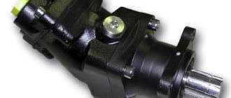
So, how to determine the rotation of an axial piston pump visually?
- We take the hydraulic pump and place it with its “hump” up.
- We look at the pump from the back cover. (Not the shaft, not the arrows on the case or the tag, since the tag or arrow on the case could have been changed or knocked down. On the cases of new models there are no such arrows at all; they are cast in the shape of a rectangular platform).
- I repeat that if this hydraulic machine is a pump, it has holes of different diameters (the hydraulic motor has the same diameter). So which side of the hole has a larger diameter determines the rotation (see the figure at the bottom of the article).