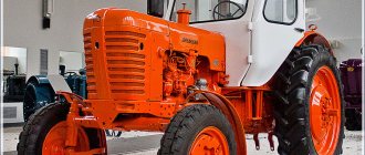
MTZ-80 tractors are considered the most common and recognizable models among other types of special equipment. They were produced by the Minsk plant, the very first model came off the container in 1974.
This model is one of the most practical in the manufacturer’s line. There is also a demand for MTZ-80 in our time. It is the interest among consumers that does not allow production to be closed and served as an impetus for the modernization of special equipment.
Important: MTZ-80 was designed based on the basic characteristics of its predecessor MTZ-50. These two models are almost completely interchangeable in terms of spare parts and components.
Main technical features
MTZ-80 is considered a universal row-crop type of equipment, which is widely used in various sectors of the economy: road, agricultural, municipal, construction. The traction class is 1.4. When properly equipped with trailer equipment, these machines can also perform loading and unloading work. Due to improved cross-country ability and high traction and grip properties, this equipment is universal in use.
MTZ-80 tractors are produced only with rear-wheel drive. Not a single modification of this type of special equipment provides for changes in this part. The engine in the MTZ-80 is located at the front, the wheels of the rear axle are larger than the front ones, and at the same time they are driving.
Today, several versions of this technology have been released, the main difference between which is the completeness of the equipment, the number of high-speed gears, ground clearance, and external design.
A characteristic feature of MTZ-80 machines is their ease of maintenance. Components for this equipment are produced both by the plant itself and are presented on the market with interchangeable analogues. Branded spare parts for the MTZ-80 can be ordered right now on the Belagro website. All products are certified, which increases their reliability in operation.
Area of use, design features
This special equipment is actively used for:
- harvesting, cultivation of row crops;
- sowing, plowing, cultivation;
- loading, transport and construction works.
MTZ-80 is a reliable, easy to operate and inexpensive to maintain tractor.
The design of the machine involves a 4-stroke engine, which guarantees high speed of movement, as well as a pneumatic system for braking trailers. The bulldozer also features a spacious sealed cabin with a heating and ventilation system. Moreover, spare parts for it are produced by domestic manufacturers, which means there will be no difficulties with repairs.
The model comes with:
- mechanical transmission;
- 9-speed gearbox;
- rear axle with locking function;
- generator;
- bogie undercarriage;
- soil tillage cutter;
- rubber cab shock absorbers;
- upholstery with good heat and sound insulation;
- opening windows for natural ventilation;
- hydraulic shock absorber for single seat.
Differences between the technology and its predecessor model
Serial assembly of the MTZ-80 began in 1974, which was preceded by testing (ended in 1972). The goal of the manufacturers was to create a more advanced and productive machine with a simple design base. The basis was taken from a tractor produced earlier - MTZ-50. The new modification was very similar to it, but was equipped with more powerful engines.
When developing the machine, we were guided by a standard layout for special equipment of this class. The MTZ-80 was created on the basis of a semi-frame type design; the equipment included load-bearing housings for transmission units. The engine was placed at the front, with the rear wheels being the driving wheels. The front ones became guides. This model belongs to rear-wheel drive tractors.
Along with this, the design has undergone some changes. When creating the MTZ-80, manufacturers modernized the following components:
- The gearbox was equipped with a reduction gearbox . Due to this feature, it was possible to double the number of speeds. MTZ-80 is equipped with 18 forward and four reverse gears.
- Clutch on clutch . Damping elements (springs) were installed in it, and the design of the flywheel was improved. It was made flat, due to which it was possible to improve the ventilation of the coupling. Additionally, we optimized the cleaning of the tank from debris and decay products that are formed by friction of surfaces.
- Automatic differential locking of the rear axle . This option in the MTZ-80 can be activated even at full speed of the vehicle.
- Rear PTO drive . By changing the design, 2 rotation speed settings were established (there is only one in the MTZ-50).
- Speed reducer . In the old version this detail was completely absent. The creeper itself is a gear reducer, which expands the speed range. With it, the minimum driving speed was 1.3 km/h.
Important : the difference between the MTZ-80 is the possibility of faster movement. The maximum speed of the car was 35 km/h. In this model, the mounted system is supplemented with various equipment: a hydraulic booster and special regulators (1 - position and 2 - power). Also, with modernization, the list of attachments that can be equipped with equipment has increased.
Technical characteristics of MTZ 80
| Engine model | D-240 |
| Engine power | 75-80 hp |
| Engine capacity | 4.75 l |
| Engine speed | 2,200 rpm |
| Transmission type | mechanical |
| Movement speed | 35 km/h |
| Hydraulic lifting capacity | 2,000 kg |
| Hydraulic system pressure | 160 kg/cm2 |
| Track width (rear wheels) | 1 400-2 100 mm |
| Track width (front wheels) | 1 200-1 800 mm |
| Ground clearance | 465 mm |
MTZ 80 video
Reviews about MTZ 80
This vehicle model has a cabin welded from thin sheet steel. It is attached to the tractor frame using four shock absorbers. This design significantly reduces the level of vibration inside. The internal walls are lined with sound and heat insulating materials.
The seat can be adjusted to suit the driver's comfort. The steering wheel position can also be adjusted. There are seat belts in the cabin.
Often, vehicle owners hear knocking noises coming from the gearbox. If they disappear when working in other gears, then this is a direct sign of wear on some gears or chipping of their teeth. To finish the job without damaging the tractor even further, you will need to immediately replace the cutter with an element with less weight. At the end of the work, you need to replace the worn gears.
Modifications and purpose of special equipment
The tractor proved itself well literally in the first years of operation. However, different regions of the Soviet Union differed in climatic and soil conditions and industrial sectors, which led to the development of modifications of the popular tractor. The machines of the main versions were designated by the following indices:
- "R" . These machines are suitable for mechanized cultivation of rice crops. They are characterized by increased ground clearance - 700 mm;
- "N" . This modification of special equipment is designed for mountain farming. These cars, on the contrary, are characterized by low ground clearance;
- "TO" . This model is designed for agricultural work on soils with steep slopes. A characteristic feature of the design of tractors of this modification is increased stability due to the use of touching gearboxes, stabilization units and the option of leveling the frame.
In addition, these versions of special equipment additionally differed in design and engine starting features.
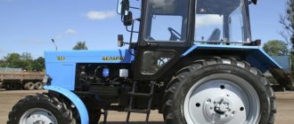
Important: today modern cars from the Minsk plant are indexed as BELARUS-80.1. Already on their design basis, approximately two dozen versions of agricultural equipment are produced with power ratings in the range of 81–95 horsepower.
Main elements of diesel engine D-243
Transmission Gearbox mechanical, stepped Clutch single-plate, dry Forward gears 18 Reverse gears 4 Forward speed, km h 1.9 34.3 Reverse speed, km h 4.09 9.22. The most popular agricultural implements mounted with a tractor include seeders, cultivators, potato harvesters, transplanters, fertilizer spreaders, etc.
Technical features and engine overview
MTZ-80 are equipped with branded engines, which are produced at the same Minsk plant. They are equipped with diesel engines D-240 and 243 (4-cylinder and 4-stroke).
The power is implied in the name and is equal to 80 horses. The rotation speed is 2200 rpm. The cooling system is liquid. Due to this feature, the tractor maintains functionality in hot and sultry conditions. The weight of the power unit is 430 kg.
An electric starter is provided for starting; the D 240 and 243 engines are equipped with it. The 240L and 243L power units use a PD-10 carburetor engine. Activation is performed from the cab, and additional functions include blocking the power unit in engaged gear. To facilitate starting in cold weather, an electric torch heater is provided.
Applications and compatible accessories
The BELARUS MTZ-80 tractor is compatible with a wide range of additional equipment:
- For agriculture and farming activities - plows, cultivators, cutters and harrows, tedders, seeders, potato planters. Various sprayers and waterers, mowers, balers, trailed feed distributors, grabs, etc.;
- For housing and communal services - rotary brushes, rotary snow plows, all kinds of trailers, semi-trailers, including dumpers, segment mowers for maintaining road slopes, pumping equipment for lawns, etc.;
- For construction and warehouses - road milling machines, buckets for processing bulk materials, hydraulic hammers, pallet forks and hydraulic loaders, various types of hydraulic tools.
One machine, complete with a set of additional equipment, can be used to solve a wide variety of problems.
Features of the gearbox
MTZ-80 is equipped only with mechanical gearboxes. There are 18 forward and 8 reverse speeds, and there is a reduction gearbox. Due to it, it is possible to ensure a smooth ride even when equipped with mounted units.
Interesting: since 1985, certain tractor models have been equipped with a hydraulically controlled gearbox and the ability to change speeds under the influence of load. This technical feature made it possible to change gears without disengaging the clutch.
Modern machines of the Minsk Tractor Plant are immediately equipped with a differential locking mechanism. To turn it off, you need to toggle the mode settings under the dashboard. In early versions of the technology, the locking was controlled by a pedal.
Analogs
Please note that to find out how much the MTZ-82 tractor weighs, you must take into account that the maximum permissible weight with attachments cannot be higher than 6.5 tons, while the nominal weight of the equipment is 3.75 tons, that is The maximum weight of attachments should be no more than 3250 kg. In early models, the differential was locked using a pedal on the floor of the cabin; in modern cars, a certain mode is simply selected on the instrument panel.
Main characteristics of the hydraulic system
Its capacity is 25 liters, the maximum pressure reaches 20 MPa, and the load capacity is 3.2 tons.
Features of equipment with mounted implements
MTZ-80 is equipped with two shafts of an independent configuration. This equipment allows you to combine equipment with different types of attachments:
- disc harrows;
- potato planters and diggers;
- shredders;
- cultivators, seeders;
- dumps (for snow removal);
- sprayers;
- trailers, etc.
Due to the wide configuration options, the MTZ-80 copes well with a variety of tasks in the agricultural, public utilities and freight transport industries.
Cabin structure and control features
MTZ-80 was immediately created for operation in the climate of Central Europe, which is characterized by cold winters. The creators took care of the driver's comfort by making the cabin a closed type. It retains heat in winter and cool air in summer. There is a hatch on the roof to provide additional ventilation.
The cabin is mounted on shock absorbers, which reduces susceptibility to shaking when driving over bumps. Wide glass is installed along the perimeter, so a wide horizon opens up.
The monitoring and control equipment is located compactly in the cab so that the driver can easily reach it. Switches and gauges are installed on the instrument panel.
Fuel consumption
MTZ-80 tractors are characterized by economical fuel consumption. On average, they consume up to 9 liters of diesel fuel per hour of operation. For example, MTZ-82 is required for the same operations up to 12 liters.
Important: diesel consumption directly depends on the engine power rating.
In order to prevent excessive fuel consumption, it is necessary to timely perform technical inspections, troubleshoot problems and replace worn-out spare parts. Helps control fuel consumption and careful operation of the engine. At high speeds it consumes more fuel.
Tractor coupling
Belarus 80 performs the following operations that are in demand for mechanized equipment:
- plowing, cultivation, harrowing of the soil;
- fertilization;
- inter-row processing;
- cargo transportation;
- cargo handling.
Such multifunctionality and versatility of the tractor is ensured by the ability to be aggregated with the following mounted and trailed specialized equipment (more than 100 models):
- various types of row crop plows;
- mounted cultivators;
- mounted harrows;
- various seeders and diggers;
- semi-trailers and tanks;
- mowers in several versions (disc, mounted);
- roll wrappers;
- bulldozer blades;
- cleaning brushes;
- watering units.
One of the popular units of the so-called hitch for MTZ 80 is a tillage cutter.
Such a cutter has the properties of several devices at once, namely a plow, a cultivator, and a disc harrow.
Together with MTZ 80, the speed of processing land plots increases and reduces the fuel consumption consumed for processing a unit of area.
Often, mass-produced cutters do not take into account the nature of the land on which they have to work and do not cope with the tasks.
Therefore, machine operators and rural specialists have to make homemade cutters for tractors with their own hands, using drawings of serial products, as well as descriptions of specialists who have already completed the modernization.
For a similar reason, we had to make homemade cultivators by hand, while making changes to the mounting of the rear hydraulic cylinder for mounting.
The KUHN front loader allows you to perform loading and unloading operations, ensures year-round use by removing snow, loading silage and hay in the winter.
Serially produced KUNs are expensive in price, and the period of use is limited. Therefore, rural specialists often make homemade KUNs on MTZ 80 with their own hands, using serial drawings.
Sometimes they are universal, and the KUN originally intended for the MTZ 80 is installed on all agricultural tractors.
Transmission of the MTZ-82 tractor
______________________________________________________________________________________________
The transmission of the MTZ-82 tractor is used to transmit torque from the diesel engine to the drive wheels of the tractor, power take-off shafts, as well as to change the magnitude and direction of revolutions and transmitted torque. Tractors use a stepped transmission, which consists of the following main mechanisms: clutch; Transmission; rear drive axle with final drive, differential and final drives. The transmission also includes a front drive axle with a final drive, a self-locking differential and wheel reduction gears, which are additionally driven by a transfer case and cardan drive. The clutch is designed to transfer power from the diesel engine to the transmission, briefly disconnect the diesel engine from the transmission and then smoothly connect them when starting the tractor, changing gears and braking.
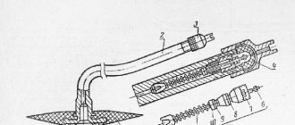
In addition, the clutch protects diesel and transmission parts from damage and breakage when the diesel engine speed or tractor speed increases sharply. Together with the clutch, a reduction gearbox and a rear power take-off shaft gearbox are mounted in one housing. The tractor is equipped with a friction, dry, single-disc, permanently closed clutch (Fig. 27), controlled by a pedal.
The transmission of torque in such a clutch is carried out due to the friction forces that arise when the drive and driven discs are compressed.
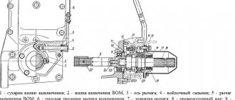
Rice. 27. Clutch, reduction gearbox and independent PTO drive MTZ-82 1 - flywheel; 2 — driven disk; 3 — pressure disk; 4 — spring cup; 5 - pressure spring; 6 — support disk; 7 — driven disk hub; 8 — damper, 9 — supporting disk; 10 — leaf spring; 11 — friction lining; 12 — limit disk. 13 — release lever; 14 — support pin: 15 — axis; 16 — pin, 17 — bushing; 18 - nut; 19 — spring; 20 - lock nut; 21 — adjusting screw: 22 — release bearing; 23 — clutch release; 24- layering bracket; 25 — intermediate gear, 26 — PTO drive drive shaft; 27 — power transmission shaft; 28- brake lifting bracket; 29 — brake activation shaft; 30 — forks; 31 — brake release; 32- drive brake disc; 33- retainer springs; 34 — ball, 35 — reduction gear shift lever; 36 — hatch cover; 37 — fork lever; 38 - drive gear of the reduction gear, 39 and 41 - needle bearings, 40 - gear clutch; 42 — driven shaft of the PTO drive; 43 - coupling; 44 — leash; 45 — PTO drive shift roller; 46 - fork; 47 — bushing; 48 - cover; 49 — driven gear of the second stage of the PTO drive; 50 — driven gear of the 1st stage of the PTO drive, 51 — forks; 52 — clutch lever; 53 - shaft, 54 - flexible hose; 55 — oiler; 56 — clutch housing. The MTZ-82 clutch is located in the dry compartment of the housing 56, connecting the engine and gearbox. The driving parts of the clutch are the engine flywheel 1, the pressure disk 3 and the stamped support disk 6. The support disk is connected to the flywheel using fingers 16, spacer bushings 17 and nuts 18. The cast iron pressure disk has three lugs evenly spaced around the circumference, which fit into the slots support disk. Release levers 13 are attached to the lugs. Twelve pressure springs 5 are installed between the support and pressure plate (basket) of the MTZ-82 clutch. On one side, the springs rest against cups 4 installed in the support disk, on the other - into the cast sockets of the pressure disk. The driven disk 2 consists of a hub 7, a connected disk with friction linings 11 attached to it, and a damper device.
Radial grooves (slots) are stamped into the connecting disk, which reduces its rigidity and improves the fit of the friction linings to the ground friction surfaces of the flywheel and pressure disk. Friction linings are made of asbestos and are equipped with ventilation grooves to improve heat removal and clean friction surfaces from wear products. The cover mating with the flywheel is riveted directly to the connecting disk. Six leaf springs 10 are first riveted to the lining mating with the basket, and then the springs are connected to the disk with steel rivets. This connection has axial compliance and provides smoother soft engagement of the clutch. When the clutch is fully engaged, the leaf springs take a flat shape, and in the free state, the thickness of the driven disk is approximately 1...1.5 mm greater than when the clutch is engaged. The driven disc of the MTZ-82 clutch is connected to the hub 7 by eight rubber dampers 8 installed in the sockets-grooves of the driven disc and the grooves of the limiting discs riveted to the hub. Thus, the driven clutch disk is connected to its hub, mounted on the splines of the power transmission shaft 27, not rigidly, but through a flexible damper device, which facilitates soft engagement of the clutch and reduces dynamic loads in the transmission. The clutch of the MTZ-82 tractor is equipped with a brake, which, when the clutch is disengaged, slows down the rotation and stops both the clutch shaft 27 and the associated input shaft of the gearbox, which facilitates gear shifting and increases the service life of the gears. The brake drive disc 32 with a glued friction lining is secured to the shaft 27 using a key and a locking ring. The splined hub of the brake lift 31 can move along the splines of the fixed bracket of the brake 28. The clutch shaft is braked when the brake discs are compressed. The clutch is released by pressing the release bearing 22 on the ends of the levers 13, which are connected with the fingers to the pressure disk 3. The adjusting screws screwed into the release levers are constantly pressed against the support pins 14 of the disk under the action of springs. When the release bearing 22 is pressed, the levers, resting the adjusting screws 21 on the pins of the support disk, rotate and move the pressure disk away from the driven one, disengaging the clutch. The basket returns to its original position under the action of springs 5. The release bearing with the offset 23 can move along the offset bracket 24 when turning the forks 51 and the release shaft 53, which is installed in bushings pressed into the clutch housing. On the right side, the hole for shaft 53 is closed with a plug; on the left side, the shaft is sealed with a felt ring. The tapping forks and the outer lever 52 are secured to the shaft 53 using keys and terminal clamps. The shaft is held against axial movements by forks covering the trunnions of the offset. The brake activation shaft 29 is installed in the holes of the housing 56 above the power shaft. On the shaft 29, with the help of keys and terminal clamps, forks 30 are fixed, moving the brake release, and the outer lever 17 (Fig. 28), connected by a rod 14 to the lever 13 (see Fig. 27) for disengaging the clutch.
Rice. 28. Clutch control of the MTZ-82 tractor 1 - pedal; 2, 7 and 18 - bolts; 3 — pedal lever; 4 - axis; 5 and 15 — springs; 6 - thrust bolt; 8- bracket; 9- oiler; 10 and 14 - thrust; 11 and 13 - forks; 12 — lever; 16 — lock nut; 17 - lever. Thus, the clutch and brake control of the MTZ-82 is interlocked and is carried out by one pedal 1 (see Fig. 28). There are two holes on the pedal rod for adjusting the position of the pedal pad relative to the cab floor. In the initial position (the clutch is engaged), the pedal is held by the spring 5 of the mechanical servo device, while the spring force is directed clockwise relative to the axis 4 of the pedal. When you press the pedal, the spring rotates relative to the fixed stop 6 and compresses until it reaches the neutral line. As soon as the axis of the spring is below the axis 4 of the pedal, the spring, expanding, creates a force directed counterclockwise relative to the axis of the pedal, which makes it easier to disengage the clutch. From the pedal lever, the force is transmitted through the rod 10 to the release shaft lever 12, which is connected by a spring-loaded telescopic rod 14 to the brake lever 17. When transmitting force, the spring 15 of the rod is compressed, facilitating smooth activation of the brake. Maintenance of the MTZ-82 tractor clutch consists of periodic lubrication, checking and tightening of threaded connections, making adjustments and eliminating identified faults. The release bearing 22 is lubricated with grease through a grease nipple 55 and a flexible hose 54, screwed into the tap pin, from where the lubricant is supplied to the bearing, as well as through a special hole to connect the tap with bracket 24. When the flexible hose 54 is not installed, the grease nipple is screwed directly into the tap pin. . To access the oiler, unscrew the plug on the left wall of the clutch housing and insert a syringe into this hole. Lubrication frequency: every 60 hours of operation. Free play of the pedal is the main indicator of correct clutch and brake adjustment. The free play of the pedal pad should be 40...45 mm, which corresponds to a gap of 3 mm between the bearing 22 and the release levers.
As the friction linings of the driven disk wear out, the free play of the pedal decreases (permissible up to 30 mm). Check free play every 240 hours of operation; Since the MTZ-82 clutch control is interlocked with the brake control, adjustment of the free play of the pedal and the length of the brake rod 14 is carried out simultaneously in the following sequence: - disconnect the brake rod 14 from the lever 12; — release the pedal from the action of spring 5, for which screw the thrust bolt 6 into the bracket 8 and loosen the bolts 7 securing it to the gearbox housing to allow the bracket to move; — by changing the length of rod 10, set the free play of the pedal pad within 40...45 mm; — turn bracket 8 counterclockwise around axis 4 until it stops against bolt 7 and secure the bracket to the gearbox housing again; — by unscrewing the thrust bolt 6 from the bracket 8, return the pedal to its original position (all the way to the cabin floor). To adjust the length of the rod 14, you need to turn the brake lever 17 together with the rod freed from the lever 12 counterclockwise until it stops and in this position, changing the length of the rod using a threaded coupling, connect it to lever 12. Having measured the length of the rod, disconnect it from the lever 12 and shorten by 7 mm. With proper adjustment, the thrust spring 15 should be additionally compressed by 3...4 mm when the clutch is disengaged, having a length of 35 mm in the compressed state. The position of the release levers 13 (see Fig. 27) is adjusted with screws 21 so that the distance from the point of contact of the levers with the release bearing to the end of the support disk hub is 12 ± 0.5 mm.
The deviation of this size for individual levers should not exceed 0.3 mm. This adjustment is made during assembly to ensure complete disengagement of the clutch. You need to engage the clutch smoothly, without holding the pedal in an intermediate position, and disengage it quickly, pressing the pedal all the way. It is not recommended to keep the clutch disengaged for a long time, and also to keep your foot on the pedal while the tractor is moving. The MTZ-82 rear power take-off shaft (PTO) drive is two-speed independent. It is located in the clutch housing and is designed to transmit rotation speeds of 545 and 1000 rpm to the rear PTO. The driving part of the drive is an elongated hollow shaft 26 (Fig. 27) with a double-crown gear, connected by splines to the hub of the clutch support disk 6, which ensures rotation of the shaft regardless of whether the clutch is on or off. The rear PTO rotates on two ball bearings, one of which is installed in the clutch release bracket, the second in the brake release bracket. The ring gears of the drive shaft 26 are constantly engaged with two driven gears 49 and 50, freely mounted on the driven shaft 42.
The first stage gear 50 can rotate relative to the shaft 42 on bronze bushings, and the second stage gear 49 can rotate on two ball bearings mounted on the hub of the first stage gear 50. The transmission of torque from the driven gears to the driven shaft 42 is carried out by means of a connecting gear coupling 43 mounted on the splines of the driven shaft.
Clutch 43 is engaged with one of the driven gears by the switching mechanism of the MTZ-82 PTO drive, located in the lower cover of the clutch housing. The shift roller 45 with the fork 46 is moved by the driver 44 using a wrench. To engage the first stage (540 rpm), you need to move the gear coupling 43 forward along the tractor. If the clutch is moved back to its extreme position, the second stage (1000 rpm) will turn on. The front support of the driven shaft 42 is a ball bearing, the rear support is a needle bearing 41. The front bearing keeps the shaft from axial movements. The driven shaft 42, through a splined sleeve, transmits rotation to the internal PTO drive shaft, which passes through the through hole of the intermediate shaft of the gearbox and, in turn, is connected to the drive shaft of the rear PTO. From the drive shaft 26 of the PTO drive through the intermediate gear 25, the hydraulic system pump is also driven. The reduction gearbox, designed to obtain an additional range of speeds, consists of two pairs of constantly meshing gears with a gear ratio of 1.34. The gearbox is located between the clutch and gearbox. At the rear splined end of the shaft 27 (see Fig. 27), a gear coupling 40 is movably mounted on the splines.
When the clutch 40, using the shift lever 35, engages the outer ring gear with the teeth of the small ring of the driven gear 4 (Fig. 29), mounted on the splines of the gearbox input shaft, the clutch shaft 27 (see Fig. 27) and the gearbox input shaft are connected directly - the gearbox is disabled. When moving forward, the coupling 40, remaining connected to the shaft 27, engages with the teeth of the small ring of the drive gear 38 of the reduction gear, mounted on a needle bearing on the shaft 27, and connects the shaft 27 to the gear 38. Rotation from the clutch shaft and gear 38 is transmitted to the double-rimmed intermediate gear 47 (Fig. 29) of the gearbox and then to the driven gear 4 of the input shaft of the gearbox.
The MTZ-82 reduction gearbox is turned on, and in all gears the speeds are reduced by 1.34 times, thus doubling the number of gears.
______________________________________________________________________________________
___________________________________________________________________________________________
Other special equipment
MTZ-80
- Creeper MTZ-80, 82
- Design of the chassis of the MTZ-80 tractor
- Gearbox MTZ-80
- Clutch MTZ-80, 82
- Maintenance and adjustment of the MTZ-80.82 gearbox
- Starting motor PD-10
- Transfer case MTZ-80
- Adjustments of drive axles MTZ-80, 82
- Steering gear and power steering MTZ-80, 82
- Braking system MTZ-80, 82
- PTO MTZ-80, 82
______________________________________________________________________________________
YaMZ-236
- Components of the YaMZ-236 HE2, BE2 cylinder block
- Clutch YaMZ-181,182,183
- Clutch discs YaMZ-236, 238
- Crankshaft and piston group YaMZ-236
- Gearbox YaMZ-236
- Diagnostics and adjustment of the YaMZ-236 engine
- Fuel supply and lubrication of the YaMZ-236 diesel engine
- Clutch YaMZ-236
- Injection pump and injectors YaMZ-236
YaMZ-238
- Cylinder block and piston group YaMZ-238
- Crankshaft and timing belt of diesel engine YaMZ-238
- Gearbox YaMZ-238
- Cooling and lubrication of diesel engine YaMZ-238
- Clutch YaMZ-238
- Fuel injection pump YaMZ-238
T-130
- Onboard clutches T-130
- Final drive T-130
- Diesel D-160 tractor T-130
- Undercarriage T-130
- Turning mechanism of the T-130 tractor
- Assembly and installation of T-130 trolleys
- Servomechanism of onboard clutches T-130
- Tractor clutch T-130
- Control mechanism for clutch and mountain brake T-130
T-170
- D-180 engine of T-170 bulldozer
- Hydraulic system of bulldozer T-170
- Hydraulic cylinder of bulldozer T-170, 130
- Repair of the main gear of bulldozer T-170, 130
- Tracks and rollers T-170, 130
- Carrying and running system T-170
- Assembly of gearbox units T-170, 130
- Tension mechanism and support roller T-170, 130
- Bulldozer equipment T-170 with rotary blade
- Adjusting the T-170 clutch
- Transmission parts for bulldozer T-170
KRAZ
- Gearbox KRAZ-255, 260
- Steering of Kraz-250, 255
- Drive axle and cardan shafts Kraz-255, 260
- Clutch Kraz-250, 260
- Power steering of the Kraz car
- Kraz car suspension
- Kraz transfer case
- Kraz power take-off
- Brake system for Kraz-6510, 65055 vehicles
- Cardan transmission and drive axles Kraz-6510, 65055
- Front suspension of Kraz-6510, 65055 cars
- Steering KRAZ-6510, 65055
- Clutch Kraz-6510, 65055
Basic systems and main units of the Belarus 80 tractor... Cooling system
| Engine D-243: technical characteristics and design These indicators are also not constant and primarily depend on the load placed on the tractor - full load with a load capacity coefficient of 1, partial 0.8, half 0.6, partial up to 0.5, as well as type of road surface: 1 group - hard surface in good condition, 2 group - gravel or crushed stone surface of average quality, 3 group - broken, high-rut surface - low quality. One of the most important factors that not only affects the fuel consumption of a tractor, but can also greatly worsen its technical characteristics, is the classification of road surfaces by type. |
| What engine is on the MTZ 80 - Special equipment kW 81 60 Diesel speed in nominal mode rpm 2200 Torque on the shaft Nm 298 Number of cylinders 4 Engine volume MTZ 80 l 4.75 Starting system Electric starter Starting gasoline engine Transmission elements Clutch unit Single-disc, dry-type gearbox Mechanical with manual switching Modes forwardreverse 184 Rate of movement forwardreverse km/h 1.9 34.34.09 9.22 Dimensions Dimensions MTZ 80 LxWxH m 4.12x1.97x2.78 Wheelbase — — 2.37 Ground clearance — — 0.645 Turning of the front outer wheel radius — — 3.8. Harrow Forks Tedgers Rakes-tedders Excavator bucket Mower Steam cultivator Plow Loader Baler Trailer Grain seeder. |