The pump in the diesel engine cooling system creates forced circulation of liquid, thereby accelerating heat exchange processes, ensuring an optimal operating thermal balance for the unit. Malfunction of the pump leads to overheating of the engine, which causes accelerated wear of the cylinder-piston group and the gas distribution mechanism of the diesel engine. A decrease in the fluid circulation rate can lead to peak overheating of the diesel engine and emergency jamming of parts.
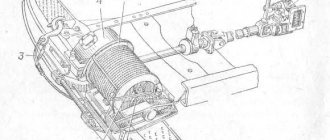
Units of the D 240 series of the MTZ 80(82) tractor are equipped with a centrifugal pump built into the water jacket of the unit. The unit is located in the front part of the diesel engine and receives drive from the crankshaft pulley through a V-belt transmission with a rotation speed, in nominal mode, up to 2600 rpm. Simultaneously with the pump drive, a fan is mounted on the unit pulley, the rotation of which accelerates the air flow through the cooling heat exchanger of the radiator.
Dismantling and repair of the water pump of the MTZ tractor
What are the signs that indicate there is a problem with the water pump?
First, a water leak appeared from the drainage hole. Secondly, you hear uncharacteristic noise and knocking noises when the water pump operates. Another breakdown of the water pump is the formation of a significant gap in the bearing or destruction of the bearing. This may cause damage to the radiator core by the fan impeller.
Loud knocking and humming are signs of extreme wear or complete destruction of the pump bearings. It is also possible that the seat of the roller under the drive pulley is unbalanced.
A coolant leak from the drain hole or oil stains on the drive pulley make it clear that the pump shaft seals have failed. To increase reliability and durability, since February 1987, the manufacturer has installed water pumps with a VAZ type seal and a reinforced bearing unit on D-240 engines.
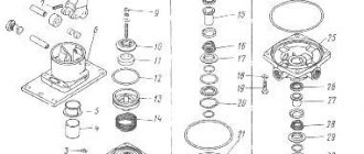
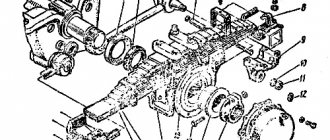
Rice. 2.1.98. MTZ tractor water pump assembly: 1 - pulley; 2 - bearings; 3 - body; 4 - impeller; 5 - drainage hole; 6 - roller; 7 - nut
To eliminate any malfunctions that appear, the water pump is removed (Fig. 2.1.99) and disassembled to replace worn-out parts (Fig. 2.1.100—2.1.105).
If the axial movement of the roller in the bearings increases by more than 0.6 mm, the roller must be replaced as an assembly with bearings. The assembly also changes if the inner rings of the bearings on the shaft become loose.
Bearings must be replaced if the radial clearance in them increases by more than 0.1 mm (Fig. 2.1.106).
Rice. 2.1.100. Layout of parts for the water pump of the MTZ tractor: 1 - pulley; 2 - bearings; 3 - impeller; 4 — body; 5 - pipe; 6 — pump roller; 7 — water pump drive belt; 8 — locking plate; 9 - nut; 10 - fan
Rice. 2.1.99. How to remove the water pump of the MTZ tractor: 1 - pulley; 2 - water pump; 3 - pipe
Rice. 2.1.101. How to unscrew the nut securing the water pump pulley of the MTZ tractor: 1 - nut; 2 - pulley; 3 - locking plate (since February 1987, there is no locking plate)
Rice. 2.1.102. Pressure testing of the MTZ tractor water pump pulley: 1 - pulley; 2 - two-jaw puller
Rice. 2.1.103. How to remove the retaining ring of the water pump bearing of a MTZ tractor
Rice. 2.1.104. How to unscrew the bolt securing the impeller of the MTZ tractor: 1 - water pump housing; 2 - impeller; 3 - bolt
Rice. 2.1.105. Pressing out the water pump roller of the MTZ tractor: 1— water pump housing; 2 — drift; 3 - impeller
Rice. 2.1.106. Pressing the bearing from the water pump roller of the MTZ tractor: 1 - bearing; 2 — water pump roller; 3 — press rod
The sealing washer of the mechanical seal can be used even if it has small ring marks and signs of wear. But their depth should not exceed 0.5 mm. In general, the thickness of the washer should not be less than 2.5 mm. The cuff must be solid; through breaks are not allowed.
If you suddenly find a crack in the water pump housing, it should be replaced. Next, the mounting surfaces of the housing for the roller bearings are diagnosed.
Nominal and permissible dimensions of the water pump of the D-240 engine, mm
| Distance from the end of the support sleeve to the parting plane: | |
| nominal | 47,0—47,3 |
| acceptable | 48,5 |
| Permissible diameter of housing holes for bearings: | |
| 305 | 62,07 |
| 304 | 52,06 |
If during the inspection you find traces of grinding (usually ring grooves) with a depth of significantly more than 0.5 mm on the end part of the pump housing support bushing, in this case the bushing is pressed out and replaced with a new one.
When assembling the pump, the rubber cuffs are placed in such a way that the flaps with the springs “look” towards the bearings. The hub nut in this case is tightened to a torque of 16-19 Nm. After assembling all the pump parts, the roller rotates by hand without braking the impeller. The ends of the edges of the fan blades are located in the same plane.
Source
Possible faults
Owners of tractor equipment from MTZ often encounter several malfunctions at once, which can have a significant impact on the quality of the unit’s operation. There may be a leak of liquid from the drainage hole, as well as the appearance of various smudges on the pulley.
As a rule, such a breakdown is associated with failure of the seals that ensure the tightness of the pump connections. The only possible solution to this problem seems to be replacing the sealing elements with new ones.
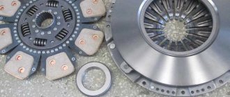
Repair kit for water pump
Another common malfunction is increased noise levels, as well as knocking noise that occurs when the pump operates. This is often caused by damaged or excessive wear on the bearings, which will require replacement. Also, a knocking noise during operation can be observed if the roller breaks at the point of contact with the belt. You can fix the problem by replacing the faulty element.
Pump repair
In order to carry out repairs of such a unit as rarely as possible, regular maintenance should be carried out, as well as a visual inspection of the main elements of the pump. If malfunctions are detected, you should immediately begin to eliminate them, which will extend the service life of the element and avoid more serious breakdowns.
You can repair the pump by following the following instructions:
- Dismantle the device. To do this, you will need to remove the pulley, the pump itself, and also disconnect the MTZ water pump pipe.
- Disassemble it into its component elements using a diagram.
- Carry out troubleshooting, paying special attention to the bearings, roller and other elements subject to the greatest loads.
- Replace damaged products with new ones.
The pulley is attached to the structure by means of a nut located in the front of the element, as well as a locking plate. The last element may be missing on tractor models produced after 1987, due to changes in the design of the tractor. After dismantling the retaining ring, it is necessary to remove the pump housing and impeller by unscrewing the fastening bolt.
Be sure to read: DIY differential for walk-behind tractor
If the tractor being repaired has a high mileage and has not undergone major repairs for a long time, cracks or other defects may form on the water pump housing. In most cases, such an element will need to be replaced, since its service life is extremely limited, and the cost of a new one is low.
It is necessary to ensure that the axial movement of the roller in the bearings does not exceed 0.6 mm, otherwise it will require immediate replacement.
Replacement
If severe damage is detected, failures of many elements, or the technician does not want to repair individual elements of the MTZ water pump, it may require a complete replacement. This procedure is noticeably simpler than a detailed repair, since it does not involve complete disassembly of the unit.
The replacement procedure involves performing the following steps:
- Remove the fan and the drive belt.
- Drain the coolant used in the cooling system.
- Unscrew the mounting bolts of the pumping equipment.
- Install a new one in place of the faulty element and repeat the procedure in reverse order.
If a plastic fan is used in the design of the tractor, it will be extremely difficult to dismantle it. You can first remove the compressor, the aluminum pipe connected to the radiator, then unscrew the pump bolts and remove the product.
It is worth remembering that since 1987, MTZ tractor equipment has been equipped with water pumps with a reinforced bearing unit, which can significantly increase the service life of the system.
Water pump functions
Studying the main features that the MTZ 80 water pump has, it is advisable to consider its functional purpose in more detail. This device, in its operating principle and design, is completely identical to the analogue that is installed in MTZ tractors of the 100 and 102 series.
It is designed for correct circulation of fluid in the cooling system, allowing the engine to operate correctly even under intense loads, avoiding overheating . The fluid, the movement of which is caused by the operation of the pump, comes from a tank located in the radiator part of the tractor and then, after passing through the system circuit, is forced out to a container located on top. Due to such circulation, it is possible to significantly reduce the temperature of the power unit, which is especially important when performing work.
Device
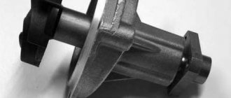
In order to be able to repair the MTZ pump with your own hands, it is extremely important to study its technical structure, as well as the principle of operation. The main design element is a durable body made of cast iron, which allows you to protect the product from various damages.
Other components of the water pump for this tractor model are:
- an impeller mounted on the shaft near the profiled part using a fastener;
- bearings with rubber cuffs, the free space between which is filled with lubricant;
- impeller seal, which separates the water and oil parts of the unit;
- thrust bushing installed in the housing;
- washers, cuffs, springs and other auxiliary elements.
The water pump is located at the front of the cylinders and begins its work simultaneously with the crankshaft. The impeller blades, driven by the engine, supply water to the channel, where the pressure increases to the required values. The liquid then flows directly to the cooling circuit.
The channel through which liquid is supplied to the system has a spiral shape, which makes it possible to create a vacuum in the inlet part, due to which water is drawn into it.
MTZ 82 tractor thermostat
The thermostat is necessary to automatically maintain the temperature in a given range and speeds up the engine warming up after starting. The thermostat device includes a housing, lower auxiliary and upper main valves, and a thermostat sensor with solid filler. The thermostat housing is made of brass, with two windows on the side surface. The upper part of the housing serves as a seat for the main valve, and the lower part serves to secure the housing in the thermostat box. The auxiliary valve lever and the main valve are attached to the top of the sensor. The thermostat is located in the housing and is installed at the outlet of the cylinder body cooling jacket. A thermostat with a solid filler is less sensitive to changes in pressure in the system and has greater adjustment forces compared to a bellows thermostat.
When the coolant temperature is less than 70º C, the main valve is closed, and the liquid is supplied through the windows through the pipe into the pump and then into the water jacket of the cylinder block. This way, the liquid does not pass through the radiator and therefore heats up faster. At a liquid temperature of more than 70º C, the volume of the mixture of cerisin with aluminum powder increases, the piston with the main valve installed on it is activated, and coolant access to the radiator opens. At the same time, the auxiliary valve blocks the windows for supplying fluid to the water pump, bypassing the radiator.
A curtain mounted in front of the water radiator regulates the volume of air passing through the radiator, thereby regulating the temperature of the liquid within a certain range. The curtain is controlled from the tractor driver's workplace using a handle connected by a cable to the movable roller of the curtain. The temperature of the coolant in the system is visually monitored using the readings of an electric thermometer, the sensor of which is mounted in the cylinder head, and the indicator itself is located in the cockpit on the instrument panel.
Thermostat: 1 - housing; 2 - auxiliary valve; 3 - window for water passage; 4 — sensor rod; 5 - main valve; 6 - sensor.
Design and principle of operation of a water pump
The diesel engine cooling water pump is a centrifugal pump that pumps coolant. The MTZ water pump consists of the following components:
- housing - it has a complex shape with two pipes - suction (connected to the line from the radiator) and pressure (connected to the line of the cooling jacket of the unit);
- shaft - transmits rotational motion from the drive to the impeller of the water pump;
- impeller - due to the rotation of the blades, liquid is supplied to the cooling system;
- drive pulley;
- oil seals - seals do not allow antifreeze to leak into the places where the water pump is attached to the main line;
- bearings.
Even though the pump is called a water pump, the coolant is not water. It was used before, on older versions of pumps, which is why they got that name. Nevertheless, today the water pump at MTZ pumps not water, but antifreeze or other technical fluid. The composition of mixtures may vary depending on climatic conditions and time of year.
Both complete failure of the water pump and deterioration of its operational parameters are dangerous. In particular, reducing the coolant circulation rate will lead to peak engine overheating. This will lead to emergency jamming of the motor parts.
The principle of operation of water pumps on different Belarusian models is the same. The pumps differ only in size and configuration, which is determined by differences in the installed motors. Let's look at the design and design features of water pumps on different MTZ tractors.
Maintenance of the D-240 engine cooling system
First of all, it is necessary to inspect all connections, monitor the serviceability of components and assemblies, the quality and level of the coolant being poured.
The cooling system must be filled only with purified water. Pay attention to the hardness of the water - hard water creates scale on the walls of the jacket, which is a poor conductor of heat and, therefore, slows down the transfer of heat from the head and walls of the cylinder block. It is recommended to use rain or snow water, which is softer, as a coolant. The hardness of water can be softened by boiling it with the addition of 10-12 grams of washing soda per 10 liters of water. The drained water from the cooling system is close in properties to boiled water and can be collected for subsequent refilling. The water is drained only when the engine is sufficiently cooled after a complete stop. The coolant temperature during engine operation should not exceed 95º C.
If the temperature rises critically, check the fluid level in the radiator and its leakage from it, as well as the degree of tension of the fan belt. Water is poured into an overheated engine evenly and always while the engine is running. During sudden cooling, there is a possibility of cracks in the cylinder head and water jacket. Do not add too hot water to a cold diesel engine in winter.
The cooling system is descaled every 960 hours of engine operation. For cleaning, you must use an aqueous solution of calcined salt (50-60 grams per liter of water). To begin with, 2 liters of kerosene are filled into the system, and then the finished solution is added. Next, start the engine and let it run for 10-12 hours. After which you can drain this liquid and refill the water.
Water pump MTZ 80 and 82
The MTZ 80 and 82 tractors are equipped with water pumps suitable for the D-240 and D-243 engines. The diesel unit is equipped with a centrifugal pump, which is built into the engine cooling jacket.
On the diagram of the MTZ water pump 80 and 82 the following details are marked with numbers:
5 – pulley of the MTZ-80 water pump;
8 – pressure spring;
| 9 – water pump impeller; 12 – sealing ring; The MTZ 80 and 82 water pump is located in the front part of the power plant. The pump is driven through a V-belt from the diesel crankshaft. In addition to the pump, a fan is mounted on the crankshaft pulley. It forces air through the radiator cooling heat exchanger. At a nominal engine speed of 2200 rpm, the water pump and fan develop a rotation speed of 2600 rpm. |
Pump device
The unit is assembled in a cast iron housing 14, consisting of two compartments: a water part in the form of a snail, where the pump impeller 9 is installed; oil - with two support bearings of shaft 4. The volute with a milled connecting surface is attached through a gasket to the block with three bolts, combining the working discharge cavity of the pump with the longitudinal line of the water jacket of the cylinder block.
The impeller is seated on the grooves of the shaft and secured with an end bolt through a washer and a rubber sealing ring. The water cavity of the volute with the impeller is separated from the oil cavity of the assembly by a partition and a seal, the tightness of which is ensured by a textolite washer 12 adjacent to the carefully ground end of the thrust bushing pressed into the body, as well as by a preloaded spring 8 of the rubber cuff 11 enclosed in a cage.
Diagram of the MTZ 80(82) pump
The vacuum created by the rotation of the impeller sucks coolant from the pipe coming from the lower can of the radiator. The liquid captured by the blades from the receiving chamber of the cochlea accelerates into the block, receiving heat from the cylinders.
The pump shaft rotates on two ball bearings installed in the oil compartment of the housing, isolated on the outer sides by oil seals 13.16. The axial movement of the outer bearing and shaft is limited by a retaining ring 6 installed in the recess of the housing. The bearings are lubricated through oil nipple 7 in the upper part of the housing. A flange hub 2 is installed on the front part of the shaft through a key 3, to which a drive pulley 5 and a fan 1 are attached. A drainage hole at the bottom of the housing drains leaked liquid out through the impeller seal. The appearance of a leak through the hole is a signal that the seal is broken.
Versions of the unit produced by the Minsk Tractor Plant, starting from 1987, differ from the design described above: in shaft diameter; reinforced rotation bearings on bearings with closed cages without sealing seals; the water cavity is isolated by a fiber seal in a metal casing.
Fiber seal for water pump MTZ 80
Original components produced by MTZ are confirmed by a warranty card and a passport certified by wet seals. Also on the market of spare parts for MTZ there are a number of versions of the unit from different manufacturers. A distinctive feature of such pumps is their maintenance-free design, where the impeller is made of textolite or polymer and is connected to the shaft by a shrink fit without a fixing bolt.
Water pump MTZ-1221
On MTZ-1221 a water pump is installed for the D-260 engine. The pump operates similarly to the mechanisms described above and differs only slightly in terms of configuration.
The MTZ 1221 centrifugal water pump is designed for pumping liquid in the cooling system of the D-260 diesel engine. The pump pumps technical fluid or antifreeze under pressure, as a result of which excess thermal energy is removed from the piston group.
The new type MTZ water pump oil seal is installed using a special mandrel. The mechanical seal is cartridge. This means that the graphite O-ring and the mating ceramic slip ring are in a common housing. Thus, the oil seal of a new type of water pump is an assembly with a stationary part (it is pressed into the seat of the pump housing) and a movable part (it is pressed onto the shaft of the water pump of the MTZ tractor). Thanks to this design, additional isolation of the bearing block from the cooling system fluid is not required.
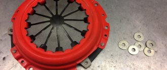
The MTZ-1221 water pump has better sealing due to the presence of a sealing rim made of silicone sealant. When the pump is installed in its seat, the sealant fills all the irregularities. If the repair kit comes without a factory layer, you will need to apply the silicone sealant yourself when installing the part.
Which pumps are suitable for different MTZ: compliance with engines and catalog numbers
Let's look at what water pumps are installed on various MTZ tractors, depending on the model and year of manufacture.
Catalog number of the water pump (article)
Suitable for enginesTractor model1307010D-240, D-245MTZ-801307010-A1D-240, D-242, D-243, D-244, D-245MTZ-82.1, MTZ-821, MTZ-80, MTZ-90, MTZ-92, MTZ- 510, MTZ-512, MTZ-520, MTZ-522, MTZ-9521307121D-260MTZ-12211307012-A1D-240MTZ-82.1, MTZ-800, MTZ-900, MTZ-822, MTZ-922, MTZ-923, MTZ- 90, MTZ-92, MTZ-510, MTZ-512, MTZ-520, MTZ-5221307010 A1-MD-240, D-241, D-242, D-243, D-244, D-245MTZ-80, MTZ -82, MTZ-821, MTZ-90, MTZ-92, MTZ-822, MTZ-923, MTZ-9221307115/1307116D-260MTZ-12216584.447.188DVS LamborghiniMTZ-3203ld-1307010-BDVS LamborghiniMTZ -3201307010-A1-08MD-245MTZ -80, MTZ-82How to remove a water pump from MTZ
To replace the MTZ water pump, you must first remove the old pump. This is not so easy to do, since there is practically no free space between the block and the radiator.
Before proceeding to replacing the water pump, you need to drain the liquid from the MTZ cooling system. To do this, a drain hose with a canister is connected to the faucet.
To remove the water pump, perform the following steps:
- raise the tractor hood;
- on the right side of the tractor, unscrew the radiator diffuser, loosen the generator brackets and remove the rod and hose to the heater;
- on the left side, the compressor and diffuser are also removed, the pipe is disconnected from the pump;
- take out the water pump.
The numbers on the diagram indicate:
More information on how to remove the water pump from the MTZ can be found here:
How to disassemble a water pump on a MTZ tractor
The design of the water pump on different Belorus tractors is almost the same, so the disassembly principle will be identical, with the exception of small features that do not pose any particular difficulty during dismantling. Let's look at how to disassemble the water pump after you have removed it from the MTZ:
- Remove the fan.
- Unscrew the nut that secures the pulley to the shaft.
1 – nut, 2 – pulley, 3 – locking plate (it is present only on old-style tractors; on machines manufactured after 1987, there is no locking plate).
- Press the pulley using a special puller.
The water pump housing must be securely clamped in a vice and only then remove the pulley using a screw puller.
1 – pulley, 2 – double-lever removable device for crimping.
- Remove the bearing retaining ring that holds the shaft in the housing bore.
- Unscrew the bolt securing the impeller.
1 – water pump housing, 2 – impeller, 3 – bolt.
- Pressing out the shaft using a screw puller.
On new MTZ tractors, the roller is pressed out after dismantling the impeller and seal.
1 – water pump housing, 2 – drift, 3 – impeller.
- Pressing the bearing from the roller.
1 – bearing, 2 – roller, 3 – press rod.
How to assemble a water pump? To do this, all disassembly steps are performed in reverse order. As a result, after assembling the assembly, the impeller should rotate smoothly, without distortions, without clinging to the body and without drawing a figure eight.
The most important step in assembling a water pump is installing the pulley hub on the shaft key. Care must be taken not to dislodge the key from the seat groove. Only in this case there will be no axial play when the impeller rotates. During assembly, you must thoroughly clean all contacts and use new gaskets and seals.
Radiator of the MTZ-82 tractor
A water radiator is used to cool water, which is heated in the water jacket during diesel operation. After passing through the radiator, the water is cooled under the influence of the blowing air flow from the fan. The radiator consists of a core, which consists of four rows of flat vertical tubes passed through a row of horizontal plates soldered to them. The core plates and tubes are usually made of brass. The ends of the tubes are soldered to the main outer and much thicker plates and protrude slightly above their surface. For better heat transfer, a stepped placement of tubes along the depth of the radiator was used.
The lower and upper brass tanks are attached to the main plates using bolts. There are rubber gaskets between the tanks and the plates. To connect the tanks, racks running on both sides of the core are used. There is a water supply pipe on the back wall of the upper tank. At the top of the tank there is a neck for filling water, closed with a plug with a steam-air valve. On the back wall of the lower tank there is a drain valve and a drainage pipe.
The radiator is installed on an elastic mount: it is attached to the front beam on supports with rubber shock absorbers, and at the top it is attached to the cylinder head with braces. You can buy a radiator for MTZ 82 in almost any store and the price for it ranges from 7 to 10 thousand rubles.
To create an active air flow, a fan is used to blow through the cores of the water and oil radiator, as well as to cool the outer surface of the engine. The fan is located in a single unit with the water pump and is located on its shaft. Using six bolts, the fan is attached to the pump pulley, and the entire complex (water pump-fan) is bolted to the top of the front side of the cylinder block. The fan shroud is attached to the rear of the water radiator struts and serves to protect the fan from foreign objects, as well as to direct the air flow to the engine.
Radiator and fan: 1 - fan; 2 - hub; 3 - key; 4 - pump shaft; 5- pulley; 6 — retaining ring; 7 - oiler; 8 - spring; 9 — impeller; 10 - cuff; 11 — clip; 12 - sealing washer; 13 and 16 — oil seals; 14 — body; 15 — fan belt.
Water pump repair
We list the main breakdowns that can be used to judge the failure of the pump on the MTZ 82 tractor and others:
- there is a coolant leak from the drain hole;
- traces of oil smudges appeared on the pulley; violation of the tightness of the pump connections;
- There was an extraneous noise when the water pump was running.
The new MTZ water pumps are equipped with more reliable seals and reinforced bearings.
As a rule, the repair of a water pump on a MTZ tractor involves:
- loss of elasticity of seals;
- damage to the seals (violation of their tightness);
- system overheating;
- mechanical abrasion of parts due to improper installation (lack of alignment, poor-quality pressing, etc.);
- entry of dirt and solids into the cooling system;
- the use of low-quality liquids that produce sediment or scale during operation.
Not all breakdowns require a complete replacement of the water pump on the MTZ tractor. Quite often, it is enough to go through the unit and install a new repair kit, choosing an option with a suitable configuration. Let's consider the main stages of current and major repairs of a water pump using the example of MTZ 80 or 82.
Water pump maintenance and inspection
When operating the MTZ tractor in a warm climate, it is allowed to fill the cooling system with distilled water. In the cold season, low-freezing liquids – antifreeze – are used. But antifreeze can be used all year round.
Scheduled maintenance of the MTZ water pump involves:
- checking the coolant level;
- monitoring its temperature (optimally maintaining it in the range of 75-95 degrees);
- checking the fan belt tension;
- visual inspection of the unit for leaks and oil stains.
Pump faults
The cause of wear of parts and subsequent failure of the unit is a violation of the tightness of the seals. Destruction of seals occurs as a result of temperature, mechanical loads during rotation, as well as friction when solid oxide particles and scale enter the engine water jacket.
If a minor pump leak is detected, it is recommended to carry out an inspection and replace the seals of the unit. Ignoring it leads to unacceptable wear of parts, which subsequently increases the repair budget. An unfortunate result of untimely maintenance is the discovery, during disassembly of the pump, of mechanical chips and gouges in the cast iron casing in the seal contact areas. Often, replacing seals in a damaged housing does not have a positive effect and the pump continues to leak. In the end, you have to purchase and install a new unit.
MTZ 80 assembly diagram
Some “Kulibins”, in order to extend the service life of the pump, drill a hole for the shaft in the volute to a larger diameter. A stainless bushing with outer rubber rings is installed in the bored hole, and self-locking oil seals are selected in the end recess of the bushing from the impeller side. The success of such a restoration depends on the accuracy of the fit of the sleeve and the tightness of the seals.
Also, an additional risk when unacceptable axial clearances appear in the pump shaft rotation supports may be damage to the radiator by the fan blades. Runout when bearings wear out can cause destruction of the key connection and the seat of the pulley with the shaft. Considering the constant axial load from the tension force of the drive belt, when unacceptable gaps are developed, the pulley with the fan moves towards the radiator, thus damaging the heat exchanger with its blades.