Starting motor gearbox - DT-75M:
01-19s11 01-19s5-1 41-19s7 4T6-19s3 4T6-19s6 6T2-19s11 6T3-19s16 SMD8-19s6 1 2 3 4 5 6 7 7 8 9 10 11 12 13 13 14 15 16 17 18 19 20 21 22 23 24 25 26 27 28 29 30 31 33 34 35 35 36 36 37 38 39 40 41 42 43 44 45 46 47 48 49 50 51 51 52 53 54 55 56 57 58 59 60 61 62 63 64 65 66 67 68 69 70 71 72 73 74 75 76 77 78 78 79 79 80 81 82 83 84
List of components for starting motor gearbox for DT-75M
Parts diagrams are for reference purposes only! We do not sell all spare parts for the starting motor gearbox for the DT-75M presented in this list. If there is a “Show prices” link in the right column, these spare parts from the “Starting Motor Gearbox” are on sale. Availability in warehouses for details and prices, see the product card. If there is no “Show cost” link in the right column, we do not sell such parts and do not accept orders for them.
| № | Part code | Name | Part Information | Show all prices |
Not available:
| № | Part code | Name | Part Information |
| 01-19s11 | Cover assembly | Quantity per DT-75M 1 | Not available |
| 01-19с5-1 | Hub assembly | Quantity per DT-75M 1 | Not available |
| 41-19с7 | Clutch gear assembly | Quantity per DT-75M 1 | Not available |
| 4Т6-19с3 | Gear housing assembly | Quantity per DT-75M 1 | Not available |
| 4Т6-19с6 | Cover assembly | Quantity per DT-75M 1 | Not available |
| 6Т2-19с11 | Pressure disk assembly | Quantity per DT-75M 1 | Not available |
| 6Т3-19с16 | Power lever handle | Quantity per DT-75M 1 | Not available |
| SMD8-19s6 | Holder assembly | Quantity per DT-75M 1 | Not available |
| Key-segm—4Х6.5, -GOST-8795-58 | Segm key 4Х6.5, GOST 8795-58 | Quantity for DT-75M 2 | Not available |
| 6T3-1913 | Activation mechanism gear | Quantity per DT-75M 1 | Not available |
| 6T3-1911 | Gear | Quantity per DT-75M 1 | Not available |
| Cylindrical pin-8Pr13X16-N507-66 | Cylindrical pin 8Pr13X16 N507-66 | Quantity for DT-75M 2 | Not available |
| 6T3-1919 | Bolt | Quantity per DT-75M 1 | Not available |
| Spring washer-12N-65G,-GOST-6402-61 | Spring washer 12N 65G, GOST 6402-61 | Quantity per DT-75M 1 | Not available |
| 6T3-1920 | Spring | Quantity for DT-75M 5 | Not available |
| Ball-VV-8-mm-R, -GOST-3722-60 | Ball VV 8 mm R, GOST 3722-60 | Quantity per DT-75M 1 | Not available |
| 01-1968 | Pad | Quantity per DT-75M 1 | Not available |
| Cylindrical pin-5S3X12, -GOST-3128-6 | Cylindrical pin 5S3X12, GOST 3128-60 | Quantity per DT-75M 1 | Not available |
| Ball bearing-No.-205,-GOST-8338-57 | Ball bearing No. 205, GOST 8338-57 | Quantity per DT-75M 1 | Not available |
| Ball bearing-No. 8109, - GOST-6874-54 | Ball bearing No. 8109, GOST 6874-54 | Quantity per DT-75M 1 | Not available |
| Bolt-М10Х25-кл—2-015, -GOST-7796-62 | Bolt M10X25 class. 2-015, GOST 7796-62 | Quantity for DT-75M 4 | Not available |
| SMD2-1927 | Finger | Quantity for DT-75M 2 | Not available |
| Bolt-М8Х35-кл—2-015, -GOST-7795-62 | Bolt М8Х35 class. 2-015, GOST 7795-62 | Quantity per DT-75M 1 | Not available |
| 01-1971 | Lock washer | Quantity for DT-75M 2 | Not available |
| 01-1907-1 | Hub | Quantity per DT-75M 1 | Not available |
| 01-1972 | Sleeve | Quantity for DT-75M 2 | Not available |
| Ball bearing-No. 8106, - GOST-6874-54 | Ball bearing No. 8106, GOST 6874-54 | Quantity per DT-75M 1 | Not available |
| 4Т6-1906 | Gear shaft | Quantity per DT-75M 1 | Not available |
| Bolt-М8Х45-кл—2-015, -GOST-7795-62 | Bolt M8X45 class. 2-015, GOST 7795-62 | Quantity for DT-75M 5 | Not available |
| 6T2-1937 | Spring | Quantity per DT-75M 1 | Not available |
| 6T2-1906-1 | Pressure disk | Quantity per DT-75M 1 | Not available |
| 6T3-1906 | Pressure stop | Quantity per DT-75M 1 | Not available |
| 6T3-1921 | Washer | Quantity per DT-75M 1 | Not available |
| 6T3-1922 | Lock washer | Quantity per DT-75M 1 | Not available |
| Bolt-М12Х25-кл—2-015, -GOST-7796-62 | Bolt M12X25 class. 2-015, GOST 7796-62 | Quantity per DT-75M 1 | Not available |
| 6T3-1905 | Fixed stop | Quantity per DT-75M 1 | Not available |
| 6T3-1902 | Lid | Quantity per DT-75M 1 | Not available |
| Spring washer-14N-65G,-GOST-6402-61 | Spring washer 14N 65G, GOST 6402-61 | Quantity for DT-75M 3 | Not available |
| Hairpin-М8Х18-Н478-66 | Hairpin М8Х18 Н478-66 | Quantity for DT-75M 3 | Not available |
| SMD8-1997 | Washer | Quantity per DT-75M 1 | Not available |
| Washer-9Х20Х2-Н497-66 | Washer 9Х20Х2 Н497-66 | Quantity per DT-75M 1 | Not available |
| Bolt-М14Х150-кл—2-015, -GOST-7795-66 | Bolt M14X150 class. 2-015, GOST 7795-66 | Quantity for DT-75M 3 | Not available |
| Spring washer-8N-65G,-GOST-6402-61 | Spring washer 8N 65G, GOST 6402-61 | Quantity on DT-75M 16 | Not available |
| Nut-M8-cl—2-055,-GOST-2524-62 | Nut M8 class. 2-055, GOST 2524-62 | Quantity for DT-75M 8 | Not available |
| 01-1903-1 | Activation mechanism cover | Quantity per DT-75M 1 | Not available |
| Spring washer-N6-65G,-GOST-6402-61 | Spring washer N6 65G, GOST 6402-61 | Quantity per DT-75M 1 | Not available |
| 6T3-1936 | Set screw | Quantity per DT-75M 1 | Not available |
| 6Т3-1912-1 | Inclusion roller | Quantity per DT-75M 1 | Not available |
| Bolt-М8Х25-кл—2-015, -GOST-7796-62 | Bolt M8X25 class. 2-015, GOST 7796-62 | Quantity for DT-75M 5 | Not available |
| 6Т3-1914-1 | Switch lever | Quantity per DT-75M 1 | Not available |
| Spring washer-10N-65G,-GOST-6402-61 | Spring washer 10N 65G, GOST 6402-61 | Quantity for DT-75M 5 | Not available |
| 6T3-1947 | Kernel | Quantity per DT-75M 1 | Not available |
| 6T3-1948 | Frame | Quantity per DT-75M 1 | Not available |
| 01-1917 | Slave disk | Quantity per DT-75M 1 | Not available |
| 01-1908 | Overrunning clutch housing | Quantity per DT-75M 1 | Not available |
| Roller-V15Х30-Н31-58 | Roller V15Х30 Н31-58 | Quantity for DT-75M 4 | Not available |
| 4T6-1903 | Pressure disk | Quantity per DT-75M 1 | Not available |
| 4T6-1905 | Clutch gear | Quantity per DT-75M 1 | Not available |
| 6T2-1949 | Adjustment ring | Quantity for DT-75M 2 | Not available |
| Ring-NE-40, -GOST-9301-99 | Ring NE-40, GOST 9301-99 | Quantity per DT-75M 1 | Not available |
| Ball bearing-No.-208,-GOST-8338-57 | Ball bearing No. 208, GOST 8338-57 | Quantity per DT-75M 1 | Not available |
| Cuff-II-55-Н536-66 | Cuff II-55 N536-66 | Quantity per DT-75M 1 | Not available |
| Hairpin-М8Х55-Н478-66 | Hairpin М8Х55 Н478-66 | Quantity for DT-75M 2 | Not available |
| 6T3-1923 | Pad | Quantity per DT-75M 1 | Not available |
| ASMD7-1901-1 | Gear housing | Quantity per DT-75M 1 | Not available |
| 6T3-1924 | Pad | Quantity per DT-75M 1 | Not available |
| 01-1919 | Engagement gear | Quantity per DT-75M 1 | Not available |
| SMD8-1994 | Bolt | Quantity for DT-75M 4 | Not available |
| 6Т2-1920-1 | Plate | Quantity per DT-75M 1 | Not available |
| 01-19108 | Lock washer | Quantity per DT-75M 1 | Not available |
| Bolt-М8Х20-кл—2-015, -GOST-7796-62 | Bolt M8X20 class. 2-015, GOST 7796-62 | Quantity for DT-75M 4 | Not available |
| SMD2-1928 | Pusher spring large | Quantity per DT-75M 1 | Not available |
| 01-1967 | Pusher spring small | Quantity per DT-75M 1 | Not available |
| Wire-01.2Х115, -GOST-3282-46 | Wire 01.2Х115, GOST 3282-46 | Quantity per DT-75M 1 | Not available |
| 6T3-1940 | Sleeve | Quantity per DT-75M 1 | Not available |
| Stopper-IM14X13-cl—2a,-N519-66 | Stopper IМ14Х13 class. 2a, N519-66 | Quantity for DT-75M 2 | Not available |
| SMD7-1539 | Pad | Quantity for DT-75M 2 | Not available |
| 6T2-1938-1 | Ring sealing | Quantity per DT-75M 1 | Not available |
| 4T6-1908 | Sleeve | Quantity per DT-75M 1 | Not available |
| Hairpin-М8Х22-Н478-66 | Hairpin М8Х22 Н478-66 | Quantity for DT-75M 2 | Not available |
| Ring-VE-80, -GOST-9301-59 | Ring VE-80, GOST 9301-59 | Quantity per DT-75M 1 | Not available |
| 4T6-1904 | Sleeve | Quantity per DT-75M 1 | Not available |
| SMD2-1932 | Emphasis | Quantity for DT-75M 4 | Not available |
| 01-1984 | Plunger | Quantity for DT-75M 4 | Not available |
| 6T2-1932 | Disk | Quantity for DT-75M 3 | Not available |
| SMD2-19375 | Holder weight | Quantity for DT-75M 2 | Not available |
| Cotter pin-3.2Х18-005, -GOST-397-64 | Cotter pin 3.2Х18-005, GOST 397-64 | Quantity for DT-75M 4 | Not available |
| SMD2-1933 | Load axis | Quantity for DT-75M 2 | Not available |
| SMD2-1931 | Holder | Quantity per DT-75M 1 | Not available |
| SMD2-1925-1 | Pusher | Quantity per DT-75M 1 | Not available |
| 14-1996 | Pusher bushing | Quantity per DT-75M 1 | Not available |
| 14-1953 | Lock washer | Quantity per DT-75M 1 | Not available |
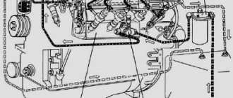
Rice. 1. Starting motor: 1 - crankshaft; 2 - cuff; 3 — flywheel housing; 4 - flywheel; 5—piston pin; 6—piston; 7 - cylinder; 8 — cylinder head; 9—candle; 10—high voltage wire; 11 — crankshaft gear; 12 - crankcase; 13 — carburetor; 14 — air damper control lever; 15 — air cleaner; 16 — carburetor throttle lever rod; 17 — lever; 18—magneto; 19 — intermediate gear; 20, 21 — ball bearings; 22 — crankshaft crank pin; 2 - roller bearing; 24 — connecting rod; 25 — crankshaft crank cheek; 26 - roller bearing
The crankcase, consisting of two halves connected by bolts, is the base of the entire engine and at the same time a purge chamber into which fresh combustible mixture is sucked in. The magneto speed regulator and the starting motor flywheel housing are attached to the crankcase.
At the top of the crankcase there is a plug for filling oil into the gearbox, at the bottom there is a plug for draining condensate.
The cylinder is attached to the engine crankcase with four studs. There are five windows on the working surface of the cylinder at different levels: exhaust, purge and inlet. From above, through an asbestos steel gasket, the cylinder is closed with a head, which is secured with four studs. The head has a spherical combustion chamber; a spark plug and a bleed-fill valve are screwed into it. The double walls of the cylinder and head form an engine cooling jacket, which is connected to the diesel cooling system by a water inlet pipe installed on the cylinder and a water outlet pipe on the head. The carburetor and muffler are attached to the cylinder flanges.
The crank mechanism includes a piston, connecting rod, crankshaft and flywheel.
The piston is aluminum, the piston bottom is convex. Two compression rings are installed on the piston, which are secured with pins to prevent rotation. The piston pin is floating; the pin is held in place by retaining rings against axial movement in the piston bosses. For correct installation of the piston, an arrow is stamped on its bottom, which should be facing towards the exhaust ports. The lower compression ring pin is also installed in the same direction.
The connecting rod is one-piece, a bronze bushing is pressed into the upper head of the connecting rod, and cylindrical rollers are installed in two rows in the lower head. To lubricate the piston pin, four holes are drilled in the upper head and bushing of the connecting rod. The roller bearing is lubricated through two cutouts in the lower end of the connecting rod.
The crankshaft is composite and is assembled from two axle shafts pressed into steel cheeks and a hollow crank pin connecting both halves of the shaft. The pin enters the lower head of the connecting rod. The crankshaft axis is shifted from the cylinder axis by 5 mm to the right when viewed from the flywheel. The main journals of the shaft rotate on roller bearings protected by oil seals. To lubricate them, there are inclined channels in the crankcase.
The gear and flywheel are secured to the crankshaft axle shafts using keys and nuts. The flywheel has a gear ring for starting the engine with a starter and a groove for manual starting with a cord.
The gear transmits rotation to the intermediate gear, and the latter to the gearbox clutch gear, the governor drive gear and the magneto drive gear. The gears are installed according to the marks on their end surfaces.
The parts of the crank mechanism are lubricated with oil contained in the combustible mixture supplied to the crankcase and engine cylinder.
The gears and their bearings are lubricated by oil from the gearbox, which gets onto the intermediate gear when the engine is running.
While the starting engine is idling, a local thermosiphon circulation occurs in its water jacket and a small part of the diesel water jacket, during which the starting engine quickly warms up (to the boiling point of water), and the rest of the diesel system remains cold. Therefore, running the starting engine idling for more than two minutes is not allowed.
When the diesel engine cranks, the water pump starts working, which ensures water circulation throughout the entire cooling system, and the starting engine does not overheat. In this case, cold water flows from the diesel block through the lower pipe to the cylinder of the starting engine, and from there, when heated, it rises to the head of the starting engine and returns through the upper pipe to the diesel head.
The carburetor 11.1107 011 installed on the engine is a single-chamber, membrane type, designed for preparing a flammable mixture and adapted for remote control.
The carburetor operates with a single-mode speed controller and consists of a body, a cover, a main metering system, an idle system, a starting system and a diaphragm mechanism.
The housing contains a diffuser, a mixing chamber, an inlet neck, a fuel chamber, fuel channels and houses an air and throttle valve.
The fuel chamber cover, complete with quencher, is attached to the body. The lid has a balancing hole that connects the cavity under the lid to the atmosphere. A floatless membrane and gasket are installed between the carburetor body and the cover.
The main metering system consists of a sprayer, integral with the main fuel jet, and a check valve.
The idle system consists of a fuel nozzle, an air nozzle, an emulsion channel, a transfer port and an emulsion outlet.
The starting system includes an air damper, an air valve and a membrane seal.
The membrane mechanism serves to maintain constant pressure in the fuel chamber and dose the incoming fuel into the fuel chamber. The mechanism consists of a metering membrane, a double-arm lever with a flat rubber fuel valve attached to it, and a spring.
The amount of fuel required for the carburetor to operate in various modes is ensured by the forced opening of the fuel valve by pressing the membrane on the heel of the double-arm lever. The membrane moves under the influence of vacuum in the fuel chamber caused by the flow of fuel through the main metering system and the idle system.
Rice. 2. Carburetor diagram: 1 - air damper; 2 — air valve; 3 — diffuser; 4 — throttle valve; 5 — clamping bolt of the fuel supply fitting; 6 — mesh filter; 7 — fuel valve; 8 - spring; 9— main system spray nozzle; 10 — mixture quality adjustment screw; 11 — idle fuel jet; 12 — gasket; 13 — dosing membrane; 14 — check valve; IS - fuel chamber; 16 — membrane seal button; 17 — balancing hole; 18 — double-armed lever; 19 — fuel chamber cover; 20 — cover fastening screw; 21 — carburetor body; 22 — fuel supply fitting; 23 — emulsion outlet hole; 24 — emulsion transition hole; 25 — emulsion channel of the idle system; 26 — idle air jet
When the engine starts idling, the air damper closes, and while the engine is cranking under the influence of vacuum, fuel intensively flows out of the metering systems, forming a rich combustible mixture with the air entering through the gaps around the air damper and the slightly open air valve. After starting the engine, the vacuum behind the throttle valve increases, the air valve opens completely and the combustible mixture becomes leaner, the engine continues to operate with the air valve completely closed.
When operating at low idle speed (throttle valve is closed), under the influence of vacuum in the behind-throttle space, fuel from the fuel chamber through the idle fuel nozzle enters the idle emulsion channel. Air also enters here through the idle air jet and the transition emulsion channel. In the channel, air is mixed with fuel and through the hole in the channel the emulsion enters the mixing chamber. The check valve is closed.
As the throttle opens while the engine is idling, the channel opening appears behind the throttle, and the emulsion also begins to flow through it.
When the throttle is opened further, the vacuum in the diffuser increases so much that the check valve breaks away from the seat, and the main system comes into operation. In this case, fuel from the fuel chamber through the check valve seat, nozzle and atomizer enters the diffuser and is picked up by passing air. At the same time, the idle system continues to operate. The engine enters regulatory mode.
As the throttle opening increases, the vacuum in the main carburetor system increases, which causes an increase in fuel consumption through the main system. The idle system continues to operate at all load conditions, however, as the throttle opening increases, the share of fuel supplied by it in the total consumption decreases.
Disassemble and wash the carburetor in the following order: - disconnect the rod from the starting motor control lever by unscrewing the rod tip and unscrewing the tip screw a few turns;
Set the low speed adjusting screw to such a position that when the throttle axis lever is pressed, stable engine operation is ensured at minimum idle speed.
Tightening the adjusting screw increases the idle speed, unscrewing it decreases it.