16.01.2020
YaMZ 12-cylinder engines are installed on heavy special equipment, dump trucks, and diesel trains. Durable and powerful units solve the most complex problems in difficult climatic conditions. However, these ultra-reliable units also require regular maintenance. One of the most pressing questions for drivers is how to adjust the ignition on the YaMZ-240.
Adjusting the valve clearances of the YaMZ-240B engine
Construction machines and equipment, reference book
Category:
Engine YaMZ-240B
Adjusting the valve clearances of the YaMZ-240B engine
Thermal gaps between the toes of the rocker arms and the ends of the gas distribution valves ensure a tight fit of the valves on the seats and compensate for the thermal expansion of the mechanism parts during engine operation. Set the size of the thermal gap at the intake and exhaust valves to be the same within 0.25-0.30 mm. If the thermal clearances are too large, the lift height of the valves decreases, as a result of which filling and cleaning of the cylinders worsens, shock loads increase and wear on the parts of the distribution mechanism increases. With very small gaps, as a result of heating or wear of the working chamfers of the valve and head seat, the combustion chamber is not sealed, the engine loses compression and does not develop full power. The valves overheat and the chamfers may burn out.
Adjust thermal clearances on a cold engine or no earlier than 15 minutes after stopping it in the following order:
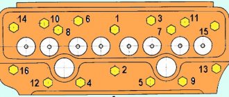
1. Turn off the fuel supply with the regulator bracket.2. Unscrew the wings securing the cylinder head covers and remove the covers.3. Tighten the cylinder head fastening nuts with a torque wrench in the sequence shown in Fig. 2.
Rice. 1. Tightening the cylinder head nuts
Rice. 2. Sequence of tightening the cylinder head nuts
Rice. 3. View of the marks for adjusting the valves: 1 - flywheel housing; 2 — hatch cover; 3 - gasket; 4 - pointer; 5 — fuel pump drive gear; a - numbers indicating cylinder numbers; b - risk
Rice. 4. View of the torsional vibration damper marks: a - when adjusting the fuel injection advance; b - when adjusting valve clearances; 1 — front cover of the block; 2 — inspection hatch cover; 3 — torsional vibration damper; 4 - pointer
4. Remove the inspection hatch located on the flywheel housing or the cover on the front cover of the cylinder block on the right side. Through the inspection hatch you can see the marks on the high-pressure fuel pump drive gear and the torsional vibration damper housing.
The combination of a certain mark with the pointer determines the position at which the clearances in the valve mechanism can be adjusted on the desired cylinder.
5. Adjust the gaps between the rocker arms and the ends of the valves of those cylinders whose numbers are indicated near the mark aligned with the indicator. To do this, use a feeler gauge to check the gaps between the ends of the valves and the toes of the rocker arms of the indicated cylinders and, if necessary, adjust them within 0.25-0.30 mm.
To adjust the gaps, unscrew the lock nut of the adjusting screw, insert the feeler gauge into the gap and, turning the screw with a screwdriver, set the required gap. Hold the screw with a screwdriver, tighten the locknut and check the gap. With a correctly adjusted gap, a feeler gauge with a thickness of 0.25 mm should enter with light pressure, and a gauge with a thickness of 0.30 mm should enter with force.
Rice. 5. Unscrewing the locknut of the adjusting screw
Rice. 6. Adjusting the valve clearance.
6. To adjust the valve clearances of the next cylinder, rotate the crankshaft in the direction of the working movement until the marks of the next cylinder align with the pointer.
Rotate the crankshaft using the rotation mechanism I installed on the flywheel housing on the right side, or using a crowbar on the flywheel through the lower hatch of the flywheel housing. Rotate the crankshaft using the cranking mechanism using a special wrench using the shank of the cranking mechanism gear, having previously engaged the gear with the flywheel ring by pressing on the shank (in position “b”). Apply force to turn while moving the key handle down. If rotation occurs when the key handle moves backwards, turn the key over to the other side.
Rice. 7. Rotating the crankshaft using the cranking mechanism.
Rice. 8. Rotating the crankshaft using a crowbar using the holes in the flywheel
Use a crowbar to rotate the shaft from left to right (in the direction of rotation of the crankshaft).
In the specified sequence, adjust the thermal clearances of all cylinders.
7. After completing the adjustment, start the engine and listen to its operation. If the gaps are large, the valves will knock.8. After making sure that the valve mechanism is adjusted correctly, close the inspection hatch and install the cylinder head covers, then make sure that there is no oil leakage from under the gaskets with the engine running.
Rice. 9. Crankshaft rotation mechanism: 1 - flywheel ring gear; 2— gear; 3 - shank; 4 — ratchet wrench; a - direction of application of force when turning the crankshaft; b - position of the gear when turning the crankshaft; c - position of the gear in the free state
Read more: Adjusting the fuel injection advance angle of the YaMZ-240B engine
Category: – Engine YaMZ-240B
Home → Directory → Articles → Forum
stroy-technics.ru
Installation advance angle of fuel injection (UOVT): step-by-step adjustment
The ignition should be set with the utmost care. Incorrect manipulations when turning the shaft will increase the time spent on maintenance and can lead to complete failure of the motor components.
"Visual" method
Locate the mark on the high-pressure fuel pump coupling and position the unit so that the mark is at the top. Rotate the engine until the friction wheel is set at 15-20 degrees. Loosen the bolts that hold the clutch in place and turn it to late injection counterclockwise. Unscrew the fuel supply pipe from the first cylinder, remove the remaining fuel in the recess and turn the clutch clockwise until fuel appears again. Tighten the bolts on the injection pump coupling.
This method is suitable for experienced mechanics and drivers. Beginners should use a torque scope or go to a service center.
Using a Momentoscope
The first stage is completely identical to the previous method: the risks must be on one side. Count the twelfth section from the drive and disconnect the fuel line from it.
Install an auxiliary device – a momentoscope – on the fitting. Activate the fuel supply with the regulator bracket. Pump fuel in the power system for three minutes. Turn the crankshaft using a ratchet wrench. This can also be done by using a crowbar to hook the flywheel from the side of the lower hull hatch. Rotate the shaft until fuel fills the mechanism tube. Drain off the excess, turn off the fuel supply and turn the crankshaft counterclockwise at an angle of 50-60 degrees. It will take about 15 swings of the key. Restart the fuel supply.
Set the OVT approximately 18-20 degrees before top dead center. When cranking the crankshaft, watch for fuel to appear in the momentoscope tube. If this happens, it means that the twelfth section of the fuel injection pump has started working. At this point, the marks on the flywheel or damper should match the marks on the flywheel housing or block cover.
It may happen that the fuel supply began earlier or later than the coincidence of the marks and indicators.
If earlier, pause the shaft rotation and perform the following steps:
- loosen the coupling half bolts;
- fix the injection advance clutch in the position when fuel begins to flow, rotate the crankshaft until the marks coincide with the indicators;
- tighten the coupling half bolts.
If later, rotate the shaft and adjust the timing of the start of fuel injection. After this, unscrew the bolts and, holding the clutch, rotate the crankshaft 15-20 degrees in the opposite direction, which is approximately equal to 4-5 swings of the key. Align the marks with the indicators, turning the shaft as it rotates, tighten the coupling half bolts.
Before adjusting the UOVT, you need to make sure that all elements of the assembly are in good condition.
Technical features and device
Each of the modifications of YaMZ 240 units has its own distinctive features. The line produces both naturally aspirated and turbocharged engines, but each of them complies with Euro-0 requirements.
By its design, the YaMZ 240 internal combustion engine is a V-shaped heavy unit with twelve working cylinders. Their main difference from other series is the increased number of cylinders, a modified camber angle and an adapted method of supporting the crankshaft journals.
The cylinders are arranged in two rows. The design is uniform with the upper part of the body, inclined at 75°. The rows were shifted relative to each other by 35 mm (the right one was moved forward) - this is due to the design of the crank mechanism.
The crankcase is made of cast iron with precisely designated places for installing liners, crankshaft, camshaft bushing and injection pump. The cylinder heads contain spring-type valves, and rocker arms and injectors are also located here. Depending on the engine model, it is possible to make individual heads for each cylinder or 3 cylinders for each head (4 in total).
The crank mechanism includes a stamped steel crankshaft with an installed liquid damper. The YaMZ 240 flywheel is cast iron. The flywheel ring gear helps start the diesel engine with the starter. The flywheel is fastened by means of bolts on the cone-shaped shank of the crankshaft to the hub pressed onto it.
The 240 engines have a mixed lubrication system with a wet sump. In turbocharged versions, the operating pistons are cooled by oil jet cooling.
The power supply is implemented by a combination of a fuel injection pump, an all-mode speed controller and a fuel injection advance clutch; two pumps supplying fuel to the injection pump; fuel lines (high and low pressure), filters (coarse and fine), injectors.
The engine is cooled by liquid cooling. The coolant circulates under the influence of the pump, entering the jackets of both rows of the cylinder block. Then it follows through the heads and accumulates in special pipelines. The heated liquid is transferred through thermostats to the radiator, where it is cooled by a fan.
Army and weapons
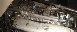
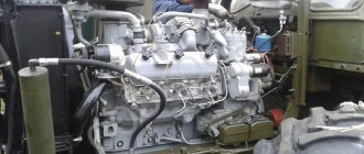
Diesel YaMZ-240B (tractor K-701)
The YaMZ-240B diesel engine differs from the YaMZ-240 engine by derating its rotation speed (1900 instead of 2100 min-1). In addition, its front part is made taking into account the operating features of the cooling system, which is more developed and has a high-performance fan with a fluid coupling.
The YaMZ-240B engine is four-stroke, with cylinders arranged in two rows, made in one block together with the upper part of the crankcase. The direction of rotation of the crankshaft is right. The operating order of the cylinders is: 1—12—5—8—3—10—6—7—2—11—4—9. Cylinder diameter 130 mm, piston stroke 140 mm, compression ratio 16.5. There are two valves per cylinder (one is inlet, the other is exhaust). Valve timing: intake valve opening 20° BTDC, exhaust valve opening 56° BTDC; closing of the exhaust valve is 56° after TDC, and closing of the intake valve is 20° after TDC. Valve plate diameter: intake - 61 mm, exhaust - 48 mm; valve lift height 13.5 mm. The gap between the valve and the rocker arm in a cold state is 0.25-0.30 mm. The fuel injection advance angle is 19°±1° before TDC. The pressure at which the nozzle needle begins to rise is 16.5±0.5 MPa. The weight of the unfuelled engine at the time of delivery is 1670 kg; its length is 1688 mm, width 1014 mm and height 1374 mm. A cross section of the engine is shown in Fig. 2.3. The figure shows that two connecting rods are installed on each crankpin of the crankshaft: one for the right row; the other is for the left. Therefore, the right bank of cylinders is shifted forward relative to the left by 35 mm. The tunnel-type crankcase is cast from low-alloy gray cast iron of a special composition. The cylinder liners (wet type) with their collars fit into the recesses on the top shelf of the block, and are pressed from above by four cylinder heads (one or three cylinders).
The cylinders are numbered along the path from the fan to the cabin on the right (1-6) and on the left (7-12). The cylinder head is a low alloy gray cast iron casting. It is attached to the block using 14 studs. The joint between the cylinder head and the block is sealed with a steel-asbestos gasket. It houses valves with springs, valve rocker arms, rocker arms and injectors. The exhaust valve seats are plug-in. They are made of special heat-resistant cast iron and are pressed into sockets with an interference fit of 0.004-0.105 mm. The cavity of the head with the valve mechanism and nozzles is closed with a lid attached to the head with wings. The joint between the cover and the head is sealed with a rubber gasket of a shaped profile. All four heads are interchangeable.
The crankshaft is steel, stamped, contains seven main and six connecting rod journals, hardened by high-frequency currents. The connecting rod journals have internal cavities closed with plugs, in which the oil is subjected to additional centrifugal cleaning. The six cranks of the shaft are located at an angle of 120° to one another in three planes. Mounted on the front end of the crankshaft
liquid damper of torsional vibrations, and on the rear (conical) - flywheel hub. The main bearings of the crankshaft are roller bearings, the outer rings of which are pressed into the bores of the crankcase part of the block. From axial
Specifications
| OPTIONS | MEANING |
| Engine weight, kg | 930 |
| Dimensions (length/width), mm | 1425/827 |
| Cylinder block material | cast iron |
| Supply system | Direct injection |
| Engine operating order (counting from the fan side) | 1 — 3 — 4 — 2 |
| Cylinder displacement, l | 7.43 |
| Power, l. With. | 90 |
| Nominal speed, rpm. | 1750 |
| Number of cylinders | 4 |
| Cylinder arrangement | vertical |
| Piston stroke, mm | 140 |
| Cylinder diameter, mm | 130 |
| Compression ratio | 16 |
| Maximum torque at 1200 - 1300 rpm, Nm | 412 |
| Fuel | diesel |
| Minimum specific fuel consumption, kWh | 1.62 |
| Cooling system | Liquid, with forced circulation of coolant |
| Oil | In summer, diesel oil DS-11 (M12V) or M10V; in winter - DS-8 (M8V). |
| Generator | DC 214A1 or G304. |
| Hydraulic pumps | 2 gear type pumps NSh10DL and NSh46UL; driven by a gear transmission from the crankshaft. |
The engine is installed on tractors DT-75M, T-4A, T-4, excavators, rollers, motor graders, pumping units, power plants.
Engine lubrication system YaMZ-240B
Construction machines and equipment, reference book
Category:
Engine YaMZ-240B
Engine lubrication system YaMZ-240B
The engine lubrication system is mixed, based on the wet sump principle.
Oil circulation in the lubrication system is carried out by an oil pump installed on the lower plane of the crankcase of the cylinder block; The pump drive is gear-type.
The pressure section of the oil pump supplies oil from the sump under pressure to the filter. The oil filter, installed on the right side of the crankcase part of the block, is full-flow, with replaceable filter elements. A contact sensor is installed in the filter bypass valve to monitor the contamination of the filter elements. When installing a signaling device, the terminal on the bypass valve plug must be connected to the light signaling device on the tractor instrument panel, to a source of electricity and ground.
When the pressure difference before and after the filter reaches 2.5-3.0 kgf/cm2, the valve opens and part of the crude oil enters directly into the oil line. At this moment, the warning light in the driver's cabin lights up. This increase in resistance can occur when the filter elements are clogged or the oil has a high viscosity (for example, when starting the engine in the cold season).
From the filter, oil flows through channels in the block and in the thrust bearing housing into the internal cavity of the crankshaft to the connecting rod bearings and then through the channels in the connecting rods to the bearings of the upper heads of the connecting rods; the second oil path is the internal cavity of the pusher axle, pushers, pusher rods and through the channels in the adjusting screw and rocker arm to the rocker arm bearings. From the axis of the pushers, oil also flows to the camshaft bearings.
Rice. 1. Diagram of the lubrication system: A - high pressure; B - oil absorption; B—splash lubrication; 1 — pressure reducing valve of the pressure section of the oil pump; 2 - oil pump; 3 - oil drain to the radiator; 4 — oil radiator safety valve; 5 — oil pump intake; 6 — shut-off valve of the oil pump; 7 - bypass valve; 8 — oil pump; 9 - crankshaft; 10 - from the oil cooler to the engine sump; II - oil supply to the crankshaft bearings; 12 — centrifugal oil filter; 13 — fluid coupling of the fan drive; 14 — fluid coupling switch; 15 — oil filler neck; 16 — oil supply to the high-pressure fuel pump; P - draining oil from the injection pump housing; 18 — pusher axis; 19 — oil filter; 20 — oil filter bypass valve; 21 - differential valve
The oil that has passed through the engine is drained into the sump.
Some of the oil undergoes additional cleaning in a centrifugal filter.
In addition, oil from the oil channel of the cylinder block flows through the outer tube into the hydraulic clutch of the fan.
Before starting, the engine lubrication system is filled with oil using an electric oil pump.
To stabilize the pressure in the engine lubrication system, a differential valve is installed, adjusted to start opening 5.2-5.6 kgf/cm2.
Read more: Oil pump of the YaMZ-240B engine
Category: – Engine YaMZ-240B
Home → Directory → Articles → Forum
stroy-technics.ru
Sequence of work execution.
Pump installation.
1. Remove the housing from the hole in the front distribution panel.
2. Determine the position of the wide tooth of the splined flange of the fuel pump drive gear and insert the splined bushing of the fuel pump into the splined washer of the pump drive gear.
3. Bolt the fuel pump to the engine.
4. Attach the fuel supply control rod to the regulator lever so that when the fuel supply control lever is in the rearmost position, the regulator lever occupies the position corresponding to the maximum fuel supply.
5. Connect the high pressure fuel lines to the fittings of the injectors and pump head according to the engine operating order.
6. Connect the fuel lines to the pump,
7. Open the supply valve and fill the engine supply system with fuel.
8. Pump fuel with a manual pump until a stream of fuel without air bubbles appears from the drain pipe.
9. Close the purge valve and tighten the handle of the manual pump.
Checking the fuel supply start angle.
1. Disconnect the high pressure fuel line from the fitting of the first section of the fuel pump.
2. Screw the momentoscope onto the fitting using a nut.
3. Install the arrow-pointer on the water pump housing so that its end is at the outer surface of the fan pulley.
4. Check the position of the fuel supply control lever to the maximum value.
5. Pump diesel fuel with a manual pump by opening the purge valve.
6. Remove some of the fuel from the momentoscope tube.
7. Unscrew the mounting pin from the hole and insert its uncut end into the same hole until it stops.
8. Slowly rotate the crankshaft by the handle clockwise until the pin fits into the recess. This will correspond to the position of the piston of the first cylinder, at which it will not reach c. m.t. by the value of the feed advance angle.
Make a mark on the surface of the pulley opposite the end of the pointer arrow.
9. Rotate the crankshaft counterclockwise one-half turn and then, rotating clockwise, monitor the position of the fuel level in the momentoscope.
When the fuel begins to rise in the glass tube of the momentoscope, stop rotating the crankshaft. The pointer arrow should coincide with the mark on the surface of the pulley. If the pointer arrow does not coincide with the mark, it is necessary to adjust the feed advance angle.
10. Remove the momentoscope, install a high-pressure fuel line on the fitting of the first section of the pump and remove the pointer arrow.
Rice. Fuel pump UTN-5.
1 - pump housing; 2—thrust washer of the shock absorber spring; 3—bearing cup; 4 - plug; 5— booster pump; 6 - rotary angle with fuel supply tubes from the settling filter and from the channel of the pump housing; 7 - cam shaft eccentric; 8 - cam shaft; 9— washer with adjusting shims; 10—oil deflector; 11 — self-clamping frame rubber seal; 12 — pump housing plug; 13 — plate for attaching the fuel pump to the engine; 14 — channels for supplying oil to the pump drive gear; 15 — tube for draining oil from the oil bath; 16 — mounting flange; 17 — splined bushing of the cam shaft; 18 — spline bushing nut; 19 — pusher roller axis; 20 — pusher roller with bushing; 21 — pusher body; 22 — pusher adjustment screw; 23 — lower plate of the plunger spring; 24 — plunger spring; 25 — upper plate of the plunger spring; 26 — rotary sleeve; 27 — rack; 28 — gear ring of the rotary sleeve; 29 — plug-plug of the fuel outlet channel; 30 — plug-plug of the fuel supply channel; 31 - plunger; 32 — plunger sleeve; 33 — pressure fitting gasket; 34 — discharge valve seat; 35—discharge valve; 36 - spring; 37 - pressure fitting; 38 — clamps (front and rear); 39 - Drain tube; 40 — inspection hatch cover; 41 — fuel supply tube from the fine filter; 42 — fuel supply channel; 43 — bypass valve spring; 44 - bypass valve. 45 — fuel outlet channel; 46 - regulator; 47 — oil filler plug; 4H - oil drain plug; 49 - channel for communicating oil baths of the fuel pump and regulator.
A quick way to adjust valves on a YaMZ-238 engine
Greetings, my Digital Friend!
Due to the fact that we are rebuilding the YaMZ 238DE2 engine with our own hands, we are faced with operations to adjust the thermal clearances of the engine valves.
The main difference in the adjustment methods is not in unscrewing the adjusting nut and tightening the rocker arm adjusting screw, and not in the subsequent setting of the gap between the valve and the rocker, that is, there are no differences in the procedure for adjusting the valve itself. The differences in the methods of adjusting or checking the thermal clearance of the valves of the YaMZ engine lie in setting the TDC of the compression stroke of cylinder 1 and the further order of sequentially bringing the cylinder pistons to TDC, and each method or sequence of adjustment actions has its supporters and opponents.
It is necessary to check or adjust the clearances on a cold engine or only an hour after stopping it. The gaps should be adjusted to 0.25 - 0.3 mm (tolerance 0.2 - 0.4 mm). To adjust the valves, you need a set of feeler gauges to adjust the gaps, a 19 mm wrench and a wide screwdriver. It is very convenient to use 2 spark plug wrenches from a gas powered tool to adjust the valves.
When we adjusted the thermal valve clearances on the YaMZ-238DE2 engine, for the first time we tried the method of bringing the pistons to TDC after the intake (left) valve was activated when 2 valves were closed. Using this method, you can adjust the valves first on the 1st side of the engine, then on the 2nd side, sequentially adjusting the piston of the next cylinder to TDC, after the left intake valve is activated. This method, in my opinion, is very labor-intensive, although it allows you to set the thermal gaps quite accurately.
But a more effective and less labor-intensive way to adjust the thermal clearance of valves on an 8-cylinder engine is to adjust them in 2 steps.
The adjustment procedure is in two steps.
Rotate the CV until the marks coincide to adjust the injection timing. Next, look at the risk of the injection advance clutch of the injection pump. If the risks coincide, then the TDC of the 1st cylinder is caught; if not, the risk on the coupling will be at the bottom - this means the TDC position of the 6th cylinder.
TDC 1 cylinder:
adjust the valves of both cylinders 1, 2 - exhaust, 3 - intake, 4 - exhaust, 5 - exhaust, 7 - intake, 8 - intake.
Turn the CV 1 turn - 360 degrees, the CV marks coincide, on the injection advance coupling the injection pump mark will be at the bottom on the reverse side.
TDC 6 cylinder:
adjust the valves of both cylinders 6, 2 - intake, 3 - exhaust, 4 - intake, 5 - intake, 7 - exhaust, 8 - exhaust.
Valve locations for left-hand drive vehicles in the direction of travel: right row (passenger side) - exhaust closer to the fan and radiator, left row (driver's side) - intake closer to the radiator.
So, this method consists of installing the engine crankshaft to the mark corresponding to the TDC of cylinder 1 or cylinder 6. You can find out which cylinder is at TDC:
- Having looked at the mark of the injection advance clutch of the high-pressure fuel pump, if the risks are approximately the same, then the TDC of the 1st cylinder is set, if the risk does not match, then the TDC of the 6th cylinder is set.
- tugging at the valves on cylinders 1 and 6, if 2 valve rocker arms - intake and exhaust - move freely and tap on the top of the valve, in that cylinder the piston is at TDC.
Source
Gas distribution mechanism of Kirovets tractors
Construction machines and equipment, reference book
Category:
Tractors Kirovets
Gas distribution mechanism of Kirovets tractors
The gas distribution mechanism is overhead valve. It consists of a camshaft with a gear, swing-type roller tappets, rods, rocker arms with screws for adjusting thermal clearances, intake and exhaust valves. It is driven by a helical gear mounted on the crankshaft shank. The axial clearance in the camshaft thrust bearing should be within 0.06...0.21 mm.
The nominal clearances between the rocker arms and the ends of the valve stems in the closed state on a warm engine are 0.25 mm for intake valves and 0.30 mm for exhaust valves. The intake valves open 200 before the piston arrives. m. t. and close after n. m.t: on the YaMZ-238NB engine - through 46°, and on the YaMZ-240B engine through 56°. The exhaust valves open on the YaMZ-238NB engine 66°, and on the YaMZ-240B engine 56° before the piston reaches the bottom. m.t. and close 20 ° after the piston arrives at the c. m.t. Valve overlap on both engines in zone c. m.t. is equal to 40°, and in the n. zone. m.t.—112° at the angle of rotation of the crankshaft. The duration of opening of the valves on the YaMZ-2E8NB engine is different and is for exhaust valves - 266 ° and for intake valves - 246. The duration of opening of the intake and exhaust valves on the YaMZ-240B engine is the same and is 256 °. The shorter duration of opening of the intake valves and longer duration of the exhaust valves on the YaMZ-2E8NB engine compared to the YaMZ-240B engine is explained by the presence. turbocharging using the energy of exhaust (exhaust) gases.
Read more: Cooling system for Kirovets tractors
Category: – Tractors Kirovets
Home → Directory → Articles → Forum
stroy-technics.ru
Main tasks
The YaMZ injection pump has a complex design. Main functions and tasks:
- determination of the start of injection;
- performing gradual injection of fuel;
- ensuring injection.
In order for the car to operate properly, it is necessary to monitor the condition of the fuel pump. This is one of the main devices that ensures normal functioning. It is important to monitor the corrector, which supplies fuel through the boost. Also, the injection pump device consists of special sections. Their number is equal to cylinders.
Checking and adjusting the cyclic fuel supply and uniformity of the YaMZ-240B engine supply
Construction machines and equipment, reference book
Category:
Engine YaMZ-240B
Checking and adjusting the cyclic fuel supply and uniformity of the YaMZ-240B engine supply
Do not unnecessarily disassemble the speed controller or change the factory setting. Make the adjustments described in this section in case of significant deviations (more than 5%) of the cyclic feed and revolutions, as well as after overhauls and replacement of parts.
The sequence of checking and adjustment is as follows: 1. Check the fuel pressure in the line at the inlet to the high-pressure pump, which should be in the range of 0.5-1.0 kgf/cm2 at 930±10 rpm of the camshaft. If the pressure is higher or lower, unscrew the bypass valve and adjust the opening pressure by turning its seat. After adjustment, caulk the valve seat.2. Check the tightness of the discharge valves. In the rack position corresponding to the supply being turned off, the injection valves should not allow fuel to pass through at a pressure of 1.7-2.0 kgf/cm2 for 2 minutes. If there is a leak, replace the discharge valve.3. When the control lever rests on the maximum speed limitation bolt, check the rotation speed of the pump camshaft corresponding to the beginning of the rack ejection. The regulator should start throwing the rack at 965+30 rpm. If necessary, adjust the speed with the maximum speed limit bolt.4. When the control lever rests on the bolt for limiting the maximum rotation speed, check the number of revolutions of the pump camshaft corresponding to the end of the rack ejection (completely turning off the supply). The end of the rack ejection should be at 1040-1090 rpm of the camshaft.
Rice. 1. Adjusting the opening pressure of the bypass valve
Rice. 2. Adjusting the maximum camshaft speed
In case of deviation from the set value, unseal and remove the regulator inspection hatch cover, keeping the position of the adjusting screw unchanged.
Rice. 3. Adjustment screw
Rice. 4. Double arm screw
The speed of the rack ejection end is adjusted as follows: a) by changing the position of the screw of the double-arm lever, set the maximum rotation speed limit bolt to the start of the rack ejection at 970+20 rpm of the pump camshaft; b) check the speed of the rack ejection end. When the screw of the double-arm lever is screwed in and the start of the rack ejection is set at 970+20 rpm, the revolutions of the end of the ejection decrease, and when turned out, they increase.
5. With the control lever resting on the bolt for limiting the maximum rotation speed and 930±10 rpm of the camshaft, check the performance of the pump sections. If the average cyclic flow of the pump sections differs from the average flow of 93 mm3/cycle by no more than ±2% with uneven flow of the sections not exceeding 8%, then adjustment may not be made.
Average cyclic flow is the total flow of all sections of the pump, divided by the number of sections.
6. If the cyclic feed deviations are more than specified in paragraph 5, the adjustment procedure is as follows:
Rice. 5. Adjustment of the rack power reserve with the screw
a) when the governor control lever rests on the bolt of minimum rotation speed and at 450-500 rpm of the cam shaft, check and, if necessary, set the rack's power reserve in the direction of turning off the feed with the rocker screw, equal to 0.5-1 mm; b) when recessed corrector, stop of the control lever in the bolt for limiting the maximum rotation speed and 930 ± 10 rpm of the cam shaft, adjust the feed of each section to a value of 88–.90 mm3/cycle. The fuel supply to each pump section is regulated by the displacement of the rotary sleeve relative to the ring gear, for which it is necessary to loosen the corresponding clamping screw. When the bushing is rotated relative to the rim to the left, the feed decreases, and to the right it increases. After adjustment, check the tightness of the tightening screws; c) with the control lever resting on the bolt of the maximum rotation speed and 930±10 rpm, screwing in the corrector housing 35, increase the feed in sections to 92-94 mm3/cycle. Lock the corrector body with a lock nut; d) with the control lever resting on the bolt for limiting the maximum rotation speed and 750±10 rpm of the camshaft, check and, if necessary, adjust the fuel supply, which should exceed the fuel supply at 930±10 rpm by 6-8 mm3/cycle. Make adjustments using nut 37 of the corrector. When turning the nut, the feed decreases, when turning it out, it increases.
Rice. 6. Unscrewing the gear sector clamping screw
Rice. 7. Adjusting the fuel supply amount
Rice. 8. Tightening the nut securing the injection advance clutch
After adjustment, secure the nut with a cotter pin.
Note 1. Turning the nut until the slot coincides with the hole for the cotter pin corresponds to a change in feed by 1.5-2 mm3/cycle.2. Typically, the end of the adjustment corresponds to a weak clamping of the washer 36 between the bolt and the corrector body.
7. Check that the fuel supply is turned off with the regulator bracket. When the bracket is turned to the lower position by 45°, the fuel supply from all sections of the pump should completely stop. If the feed does not turn off, check the ease of movement and eliminate possible jamming of the rack.8. Install the injection advance clutch, having previously added oil to it, and tighten the nut securing it to a torque of 10-12 kgf-m. Tighten the clutch fastening nut using the socket wrench included in the driver's tool kit.
Tighten the injection advance clutch mounting nut in all cases when the high-pressure fuel pump is removed from the engine.
When installing fuel equipment on the engine, connect the sections of the high-pressure fuel pump with the injectors attached to the pump sections in accordance with Fig. 63.
After adjusting the fuel equipment on the stand and installing it on the engine, check the oil level in the high-pressure fuel pump and in the speed regulator, set the fuel injection advance angle using a torqueoscope, start the engine and adjust the minimum crankshaft speed within 650-750 rpm .
Adjust the minimum speed as follows: 1. Having loosened the lock nut, turn out the buffer spring housing by 2-3 mm.2. Using the minimum rotation speed limit bolt (the control lever must rest against this bolt), adjust the minimum idle speed until slight fluctuations in engine speed appear. When screwing in a bolt, the rotation speed increases, when turning it out, it decreases.3. Screw in the buffer spring housing until the speed instability disappears. It is strictly forbidden to screw in the buffer spring housing until its end aligns with the end of the locknut. After adjustment, secure the minimum speed bolt and the buffer spring housing with nuts. The minimum rotation speed can also be adjusted on a new engine during the initial period of its operation.
Rice. 9. Procedure for connecting high pressure fuel lines.
Rice. 10. Unscrewing the buffer spring housing
Read more: Replacing primary fuel filter elements for the YaMZ-240B engine
Category: – Engine YaMZ-240B
Home → Directory → Articles → Forum
stroy-technics.ru
Diesel engines of trucks and tractors. Spare parts, adjustments and repairs.
________________________________________________________________
________________________________________________________________
Maintenance of the YaMZ-240 power system
During ETO, the power supply systems check the fuel levels in the tanks, the oil levels in the high-pressure fuel pump and the speed controller, the functioning of the fuel supply drive, and drain (in winter) sediment from the fuel filters. YaMZ-240 diesel engines, produced since 1982, use a centralized oil supply to the high-pressure fuel pump and speed controller to ensure a constant oil level. Therefore, breathers with oil measuring rods have been canceled on them. During TO-1, check the tightness of the bolts securing the high-pressure fuel pump, fuel tanks, air cleaner, exhaust pipe, drain sediment from fuel tanks and filters, check the condition of the second-stage air cleaner cassettes, as well as the ease of starting the diesel engine and the uniform operation of the cylinders. During TO-2, after 240 m/h, wash the filters and fuel tank caps and replace the filter elements of the coarse fuel filter. After 480 m/h, the filter elements of the fine fuel filter are replaced, the injectors are removed and checked, the fuel injection advance angle is checked and, if necessary, adjusted. During TO-3, the functionality of the clogging alarm and the condition of the second-stage air cleaner cassettes are checked, the first stage of the air cleaner is purged with compressed air, the high-pressure fuel pump is removed and tested on a stand: the first time after the end of the warranty period and then after 960 m/h. At the service station, fuel tanks and filters are washed, fuel and lubricant are replaced in accordance with the upcoming operating season. The elements of the YaMZ-240M2 coarse fuel filter are replaced in the following sequence: - Unscrew the drain plugs and drain the fuel from the filter housings. — Unscrew the bolts securing the flanges of the filter housings, remove the housings and remove the filter elements. — Wash the housings with gasoline or clean diesel fuel. — Install new elements and cover gaskets, assemble the filter. Pump the system with a fuel pump RNM-1K and make sure the filter is tight. To eliminate fuel leakage, tighten the bolts. The elements of the YaMZ-240BM2-4 fine fuel filter are replaced as follows: — Unscrew the drain plugs and drain part of the fuel. — Unscrew the filter housing mounting bolt, remove the housing, remove the filter element and pour out the remaining fuel. — Wash the body with gasoline or clean diesel fuel. — Install a spring, washer, rubber gasket, a new filter element with the metal flange down, a rubber gasket on the upper end of the element into the housing and assemble the filter. The filter element in the second filter housing is replaced in the same way. Pump the power system with a fuel pump RNM-1K and make sure the filter is tight. To eliminate fuel leakage, tighten the bolts.
YaMZ-240 B injectors are checked and adjusted at 480 m/h. They are checked using a special device KI-3333 GOSNITI or KP-1609A for needle lifting pressure and the quality of fuel cutting. After prolonged engine operation, the needle lift pressure should not be lower than 15 MPa (see Fig. 28). When coking the holes in the nozzle, the injectors are disassembled in the following sequence: - Unscrew the cap 11 and the lock nut 14. - Unscrew the adjusting screw 13 until it stops and unscrew the spring nut 15 by 1.5-2 turns. — Unscrew the nut 20 of the sprayer and remove its body 22, protecting the needle 23 from falling out. — Unscrew the nozzle fitting 8 and inspect the strainer 7. The damaged filter is replaced with a new one. — It should be borne in mind that if you change the order of disassembling the nozzle, the fixing pins 21 may break. — The nozzle body is cleaned from the outside using a wooden block soaked in diesel oil, the internal cavities are washed with gasoline, and the nozzle holes are cleaned with steel wire with a diameter of 0.3 mm, clamped in a collet chuck. Before assembly, the atomizer body and needle are thoroughly washed in clean gasoline and lubricated with filtered diesel fuel. After this, the needle, extended from the spray body and tilted at an angle of 45°, should smoothly (without delay) completely lower under the influence of its own weight. When tightening the nozzle nut, its body is turned against the direction of screwing the nut until it stops against the fixing pins. Holding it in this position, screw the nut on first by hand, and then finally tighten it to a torque of 70-80 Nm. The injector fitting is tightened to a torque of 80-100 Nm. After assembling the YaMZ-240 injectors, the needle lifting pressure is adjusted, the quality of fuel atomization and the accuracy of the nozzle are checked. At low pressure, the nozzles are adjusted with screw 13 with cap 11 removed and locknut 14 unscrewed. When screwing in the screw, the pressure increases, and when screwing out, it decreases. During the regulation process, the nozzle needle lifting pressure is set to 16.5-17 MPa. The atomization quality is considered satisfactory if, when supplied to the nozzle at a speed of 70-80 strokes per minute, the fuel is injected into the environment in a mist-like state and is evenly distributed over the cross section of the jet and over each nozzle hole. The start and end times of injection must be clear. Injecting fuel with a new injector is accompanied by a characteristic sharp sound.
The absence of a sharp sound from used injectors when checked on a manual stand is not a defective sign. After servicing, the nozzles are installed in their original places, having previously cleared the cylinder head holes for the nozzle from carbon deposits. The injector mounting nuts are tightened to a torque of 50-60 Nm. Exceeding the tightening torque can lead to destruction of the inter-valve bridge of the cylinder head. The fuel injection advance angle is checked and adjusted after 480 m/h. On the YaMZ-240B diesel engine, adjustment operations are performed in the following sequence: - Make sure that the marks on the body of the fuel injection advance clutch and the drive half-clutch of the fuel injection pump drive shaft are in the correct relative position. The marks should be on one side. — Disconnect the high pressure pipe from the 12th section of the high pressure fuel pump. — Install the momentoscope on the fitting of the 12th section. — Turn on the fuel supply using the speed control bracket. — Bleed the power system using a manual fuel pump for 3 minutes. — Rotate the crankshaft with a ratchet wrench using the cranking mechanism until fuel appears in the glass tube of the momentoscope. Shake the tube and pour out excess fuel. — After fuel appears in the tube, turn off the fuel supply, turn the crankshaft in the direction opposite to its rotation by 50-60° (12-15 turns of the key) and turn on the fuel supply again. — Slowly turn the crankshaft until the fuel begins to move in the momentoscope tube of the 12th section and check whether the marks (marks) 19 on the torsional vibration damper coincide with the pointer on the block cover. If the moment the fuel supply starts occurs earlier or later than the mark coincides with the indicator, unscrew the bolts from the drive half of the coupling of the injection pump drive shaft and, holding the clutch in the position where the fuel supply starts, rotate the crankshaft until the mark coincides with the indicator, tighten the bolts securing the drive half of the coupling and finally check the angle setting fuel injection advance, which should be 18-20°. The ease of starting the YaMZ-240BM2 diesel engine and the uniform operation of the cylinders are checked after 60 m/h (at TO-1). Before starting a diesel engine, you need to make sure that it is in good working order, that there is fuel, coolant and oil in the systems, as well as that the batteries are charged (at least 75% in winter and 50% in summer). Before starting in winter, the diesel engine is warmed up using a heating boiler. To start the YaMZ-240B diesel engine, pump the lubrication system for 2-3 minutes using an electric oil pump, creating a pressure in it of 0.15 MPa, set the manual fuel supply handle to the position corresponding to the minimum crankshaft speed (all the way to the front wall beam cabin), press the starter start button and release it when the diesel engine is running steadily. Starting is considered easy if the duration of continuous operation of the starter does not exceed 20 seconds. The diesel engine is restarted after a break of at least 1 minute. Up to three start attempts are allowed, after which the fault must be identified and corrected. After starting, the diesel engine is listened to at different crankshaft speeds, distinguishing the noise of individual cylinders. Uneven operation of the cylinders may be the result of a violation of the adjustment of the gas distribution mechanism, injectors, as well as such malfunctions of the high-pressure fuel pump sections as freezing of the injection valve, leakage of the injection valve-seat pair, loosening of the plunger bushing ring gear, freezing of the plunger, breakage of the pusher spring, etc. etc. The high-pressure fuel pump TNVD YaMZ-240 is checked and adjusted during TO-3 in a special workshop. The pump is checked on a stand with a set of injectors removed from the diesel engine and adjusted. During further dismantling and installation work in operation, the injectors are installed in their cylinders and connected to the same sections of the pump with which they were tested on the stand. Before installing the pump on the stand, check the axial free play of the cam shaft. If the free play is more than 0.1 mm, it is adjusted with shims within 0.01-0.07 mm. When testing on a bench, the moment at which fuel injection pump sections begin to supply fuel, the cyclic supply and the uniformity of fuel supply are checked. The moment the fuel supply begins is checked and adjusted without an automatic injection advance clutch based on the moment the fuel begins to move in the momentoscope. The moment the pump sections begin to supply fuel is determined by the angle of rotation of the pump camshaft when rotating counterclockwise, as viewed from the drive side. The first section of the adjusted pump begins to supply fuel 37-38° before the axis of symmetry of the cam profile. The axis of symmetry of the cam profile is determined by the fork method: first, the moment of the start of fuel movement in the momentoscope is recorded on the dial when the cam shaft rotates clockwise, and then the shaft is rotated in the same direction by 90° and again the moment of the start of fuel movement in the momentoscope is recorded on the dial. rotating the shaft counterclockwise. The midpoint between the two fixed points determines the axis of symmetry of the cam profile. Sections of the YaMZ-240 BM2 injection pump must begin supplying fuel relative to the first section in the order specified in the passport. The inaccuracy of the interval between the start of fuel supply by any pump section relative to the first should not exceed 20″. The moment the fuel supply starts is adjusted using the pusher bolt. When the bolt is unscrewed, fuel is supplied earlier, when screwed in - later. After adjustment, tighten the locknuts on the adjusting bolts of the sections. The cyclic fuel supply and uniformity of supply are checked and adjusted on the YaMZ-240 diesel engine in the following sequence: - Check the fuel pressure at the pump inlet, which should be in the range of 0.05-0.1 MPa at a cam speed of 920-940 min-1 shaft — The pressure is adjusted by turning the pump bypass valve seat, after which the valve seat is minted. — Check the tightness of the discharge valves. When the supply is turned off, the injection valves should not allow fuel to pass through at a pressure of 0.17-0.2 MPa for 2 minutes. If fuel leaks, the injection valve must be replaced. — Check the rotation speed of the injection pump camshaft, corresponding to the moment the rack begins to move. When the governor control lever rests on the bolt for limiting the maximum rotation speed, the governor should begin to move the rack at a rotation speed of 965-995 min-1. Adjust the rotation speed with a bolt. — Check the rotation speed of the pump camshaft corresponding to the moment of the end of the rack movement (completely turning off the supply). When the governor control lever rests on the bolt for limiting the maximum rotation speed, the governor should finish moving the rack at a rotation speed of 1040-1090 min-1. — To adjust the rotation speed of the cam shaft corresponding to the moment of the end of the rack movement, you should screw in (or unscrew) the screw of the double-arm regulator lever and set the maximum rotation speed limit bolt to the moment the rack begins to move at a rotation speed of 970-990 min-1 of the pump cam shaft. — When screwing in the screw of the double-arm lever, the rotation speed decreases, when unscrewing it increases. — Check the flow of sections of the YaMZ-240B pump with the regulator control lever resting on the bolt for limiting the maximum rotation speed and the rotation speed of the cam shaft being 920-940 rpm. It should be within 91-95 mm3 per cycle. The unevenness of sections feeding should not exceed 8%. — To adjust the cyclic feed, it is necessary to use the screw of the regulator link to set the rack travel reserve to 0.5-1 mm in the direction of turning off the feed when the regulator control lever rests on the bolt and the cam shaft rotation speed is 450-500 min-1. — Then you should move the rotary sleeve relative to the ring gear of the corresponding section. When the bushing is turned to the left relative to the rim, the feed decreases, and when it is turned to the right, it increases. — After adjustment, check the tightness of the fastening screws. When the control lever rests on the bolt and the rotation speed is 920-940 min-1, screw in the corrector housing, increasing the section feed to 92-94 mm3 per cycle, and tighten the nut. — When the control lever rests on bolt 11 and the camshaft rotation speed is 740-760 min-1, check and, if necessary, adjust the fuel supply with the corrector nut, which should be 6-8 mm3 per cycle more than the fuel supply at a rotation speed of 920-940 min-1 1. When screwing the nut in, the feed decreases, when turning it out, it increases. — Turning the nut until the slot coincides with the hole for the cotter pin corresponds to a change in feed by 1.5-2 mm3 per cycle, the end of the adjustment corresponds to weak clamping of the washer between the nut and the corrector body. After adjustment, the nut is secured with a cotter pin. — Check that the fuel supply is turned off with the regulator bracket. When the bracket is rotated 45° to the lower position, the fuel supply to all sections should completely stop.
___________________________________________________________________
___________________________________________________________________
- Injection pump D-245 - design and adjustments
- Timing belt and valves D-245
- Engine lubrication system D-245
- Fuel system parts D-245
- Operations for adjusting YaMZ-236
- Operations for disassembling and installing fuel injection pump YaMZ-236
- Cooling system and lubrication system YaMZ-238
- Fuel injection pump YaMZ-238
- Characteristics of Cummins ISBe, ISLe, ISB, QSB
___________________________________________________________________
___________________________________________________________________
- Repair and replacement of Cummins ISBe, ISLe, ISB crankshaft
- Cummins ISBe, ISLe, QSB cylinder block repair
- Connecting rod and piston group Cummins ISBe, ISLe, ISB
- Diesel cooling system ISF 2.8
- ISF 2.8 diesel cylinder block and pistons
- Cummins ISF 3.8 Fuel System Components
- Cummins 3.8 engine lubrication system
- Cummins ISF 3.8 Cooling System
- Cylinder head YaMZ-7511
- YaMZ-7511 cylinder block
- Diesel crankshaft YaMZ-7511
In what cases is adjustment necessary?
Checking the installation advance angle of fuel injection on diesel units, including units of the Yaroslavl plant of the 240th series, must be performed:
- when replacing the high pressure fuel pump;
- installation of a new fuel injection unit;
- in case of detection of characteristic malfunctions: difficulty starting the engine, an abundance of white smoke, the presence of extraneous ringing sounds, increased fuel consumption.
Timely adjustment of the ignition will help to avoid additional costs for fuel, additional repairs of components such as the YaMZ 240 flywheel housing, and will also ensure comfortable and safe operation of the vehicle.
Publication date:05/03/2019
adjustment of engine valves Yamz 240
City Name Phone Dealer address Belgorod Plumbing store in Belgorod, 34-44-42, 34-19-29 Belgorod, st. Nekrasova, 33 Birobidzhan Plumbing store in Birobidzhan 8 (42622) 4-12-32 Birobidzhan, st. Sholom Aleichem, 88 Bryansk Plumbing store in Bryansk No. 1 79003640061 Bryansk, Moskovsky Avenue 19 Vidnoye Plumbing store in Vidnoye 79851958575 Vidnoye, st. Zavidnaya, 9 Volgograd Plumbing store in Volgograd 79275264991 Russia, Volgograd, Zemlyachki street, house 58 Vyazma Plumbing store in Vyazma 79066682382 Vyazma, g., st. Smolenskaya, 7 Dubna Plumbing store in Dubna 74993904118, 79167259015 Russia, Moscow region, Dubna, Pravdy street, 4s1 Ekaterinburg Plumbing store in Ekaterinburg 73432102713 Ekaterinburg, st. Surikova, 50 Yekaterinburg Plumbing store in Yekaterinburg #2 EKATERINBURG, SOFIA KOVALEVSKOY STREET, 3, OFFICE 513 Yekaterinburg Plumbing store in Yekaterinburg No. 1, 379-03-81 Yekaterinburg, st. March 8, 212 Plumbing store in Essentuki Stavropol Territory Essentuki, Novoselov St. 6 Zelenogorsk Plumbing store in Zelenogorsk “SanTechMarket” 79135104277 663690, Krasnoyarsk Territory, Zelenogorsk, st. Mira 42 Zelenogorsk Plumbing store in Zelenogorsk Shopping center Mercury 73916928003/79138311820 Russia, Krasnoyarsk region, Zelenogorsk, st. Parkovaya house 33 Ivanteevka Plumbing store in Ivanteevka 79162085623 Moscow region, Ivanteevka, st. Khlebozavodskaya, 22 Ivanteevka Plumbing store in Ivanteevka #2 Moscow region, Ivanteevka. st. Trudovaya 7 Irkutsk Plumbing store in Irkutsk +7 (395) 267-03-99 Russian Federation, Irkutsk city, Oleg Koshevogo street, house 65 Kirov Plumbing store in Kirov 78332524677 Kirov, Moskovskaya street, 102V Kirov Plumbing store in Kirov No. 2 Kirov, street Ivana Popova, 21 Kislovodsk Plumbing store in Kislovodsk 79282663304 Stavropol Territory, Kislovodsk, st. Gubina, 12 Korolev Plumbing store in Korolev 79154870730, 79686438064 Korolev st. Pionerskaya building 30 building 8 Krasnoufimsk Plumbing store in Krasnoufimsk 73439424749 Krasnoufimsk st. Lenina 53 Titan store Maykop Plumbing store in Maykop 79604995899 Republic of Adygea, Maykop, st. Kurgannaya, 234 Moscow Plumbing store in Moscow 89166897511 Moscow st. Kirovogradskaya house 13 Moscow Plumbing store in Moscow #1 +7 (499) 130-08-56 Moscow st. Bolshaya Cheryomushkinskaya, 25s112 Murmansk Plumbing store in Murmansk 183052, Murmansk, Kolsky Ave., 131 Novotroitsk Plumbing store in Novotroitsk 73537676674 Orenburg region, Novotroitsky district, Novotroitsk, st. Sovetskaya, 38 Orenburg Plumbing store in Orenburg 73532583830 Orenburg, st. Yurkina, 9a, Furniture Bazaar Orenburg Plumbing store in Orenburg TC THREE KITA 73532582430 Orenburg st. Turkistanskaya house 49 Orenburg Plumbing store in Orenburg TC Troika 73532583830 Orenburg Belyaevsoe highway house 22 Salekhard Plumbing store in Salekhard Yamalo-Nenets Autonomous District Salekhard microdistrict. Pervomaisky-2, 84 St. Petersburg Plumbing store in St. Petersburg 78129326571 St. Petersburg, Kyiv street, 3 Saransk Plumbing store in Saransk Saransk, st. Sovetskaya, 105 Vylgort Plumbing store in the village of Vylgorte 78212725552 Russia, Komi Republic, Syktyvdinsky district, village of Vylgort, Gagarina street, 5 Smolensk Plumbing store in Smolensk (4812) 32-52-42, 69-71-71 Smolensk, Ave. Gagarina, 60 building 3 Smolensk Plumbing store in Smolensk No. 2. +7 (950) 700-88-80 Smolensk, Pharmacy street, 1A Tambov Plumbing store in Tambov 74752525838 Tambov, st. Magistralnaya, 35a Tomsk Plumbing store in Tomsk 7(3822)202-803 Tomsk, Transportnaya street, 1A Tyumen Plumbing store in Tyumen 73452694744 Tyumen, st. Kamchatskaya, 194, office 211 Ulan-Ude Plumbing store in Ulan-Ude 73012373009 Ulan-Ude, st. Klyuchevskaya, 54V Ulyanovsk Plumbing store in Ulyanovsk 8-905-036-06-99 Ulyanovsk, st. Ostrovsky, 58 Khanty-Mansiysk Plumbing store in Khanty-Mansiysk Khanty-Mansiysk st. Lenina building 82 Chelyabinsk Plumbing store in Cheboksary 78352452695 Cheboksary, M. Ave. Gorkogo, 19 Chelyabinsk Plumbing store in Chelyabinsk 79193116663 Chelyabinsk, st. Mamina, 23b Chelyabinsk Plumbing store in Chelyabinsk 73512234511 Chelyabinsk, st. Dovatora, 27 Cheboksary Plumbing store in Chelyabinsk No. 1 79053462459, 79176757950 Cheboksary, st. Startovaya, 4 Cheboksary Plumbing store in Chelyabinsk No. 2 79053462459, 79176757950 Cheboksary, prosp. Traktorostroiteley, 54, building 1 Yaroslavl Plumbing store in Yaroslavl, 30-06-67 Yaroslavl, Sovetskaya st., 23 Yaroslavl Plumbing store in Yaroslavl #1 Yaroslavl, Tolbukhina Ave., 8/75 Yaroslavl Plumbing store in Yaroslavl #2 Yaroslavl , Vspoliinskoye Pole st., 1 Yaroslavl Plumbing store in Yaroslavl #3,48-60-56 Yaroslavl, pr-t. Tolbukhina, 58 Yaroslavl Plumbing store in Yaroslavl #4 +74852770048 Yaroslavl, st. Panina, 12v Optima shopping center, 2nd floor
scepio.ru