In the design of the portal driving front axle of the tractor, each pair of gears and bearing support of the shafts, participating in the kinematic chain of power transmission to the running wheels, is a critical point of the mechanism. Timely maintenance and compliance with technical parameters in setting the engagement of gear pairs and axial clearances in the bearing races of the unit ensures the ability to use the resource of the mechanism with a maximum service life without repairs. To prevent tractor failures, in this article we will cover as much as possible the topic of the causes of breakdowns in the FDA mechanism. We will also pay attention to troubleshooting technology and proper adjustment of mechanism parts during assembly.
How to assemble the gearbox of a MTZ walk-behind tractor
Unlike a tractor, the gearbox of a wheeled walk-behind tractor has a less complex device. The main differences between the walk-behind tractor transmission:
- fewer drive stages than a tractor (the MTZ-05 walk-behind tractor has 6 stages);
- constant meshing of gears in the box, no moving gears;
- lack of a separate shaft for first and reverse gears.
To independently assemble a walk-behind tractor gearbox, you will need a diagram and instructions. The sequence should be the reverse of the steps taken when dismantling the unit.
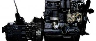
Disassembling the MTZ engine
Disassembly of diesel engines D-245, 240, 243 is carried out in the following sequence.
From the engine installed on the stand with the oil sump down, remove the thermostat with the pipe, the water pump housing and the fan assembly.
Then, unscrew the exhaust manifold mounting nuts and remove it.
Using kit I 804.10.000 inertial universal puller, remove the injectors.
Remove the cap and cover from the valve mechanism, and the oil supply tube to the rocker arm axis (if equipped).
Remove the axle stands assembled with the rocker arm axle and rocker arms and remove the rods from the cylinder block.
Unscrew the cylinder head bolts, remove the cylinder head and gasket.
Unscrew the crankshaft pulley mounting bolt from the end of the crankshaft, remove the front diesel engine mount, and then remove the pulley using a special puller.
Remove the flywheel, seal housing with rubber lip, oil slinger and rear sheet of the MTZ diesel engine.
Turn the motor 90°. Remove the camshaft gear cover, the intermediate gear, unscrew the special screw through the hole in the camshaft gear and loosen the bolt securing the thrust washer, and then, turning the camshaft, remove it from the cylinder block.
Remove the camshaft drive gear using a press and a mandrel, having first unscrewed the gear mounting bolt.
Remove the oil sump and connecting rod caps with liners; Remove the connecting rods and pistons from the cylinders and put the connecting rod caps in their places.
When disassembling a diesel engine, the pistons assembled with connecting rods should only be removed upwards. In this case, you can use the mandrel I 806.01.200. Before removing the pistons, remove carbon deposits from the top of the cylinder liners.
When replacing parts of the sleeve-piston group and crank mechanism, pay special attention to the size groups of parts.
Unscrew the bolts securing the main bearing caps and remove them together with the liners.
Remove the crankshaft and remove the tappets.
Gears can be removed from the crankshaft using a universal mod puller. 1P-21305.
Remove the compression and oil scraper rings from the pistons using tool I 804.03.000.
Remove the retaining rings from the piston bosses using pliers; press out the piston pins.
Press the cylinder liners out of the block using tool mod. And 804.01.000.
After disassembling, wash all parts of the diesel engine and blow with compressed air. For washing, use washing solutions MS-6 or MS-8 TU 6-15-978-76 with a concentration of 20.30 g/l at a temperature of 90.100 C.
Requirements for engine parts D-240, 243, 245
Engine body parts include: cylinder block, cylinder liners, gear covers, diesel engine support, etc.
Main parameters of MTZ tractor body parts
Name of parts / Material / Weight, kg / Hardness of working surfaces
Cylinder block 245-1002015-A3-02 / SCh-20 / 96.47 / 170. 241 NV
Cylinder block liner 245-1002021-A1 / Special cast iron / 4.452 / 229. 269 HB
Case ring 245-1002023-A / Rubber IRP-1345 / 0.008
Shield 240-1002030 / Steel 45 / 1.67
Cover 245-1002036 / AK5M7 (Ak9ch) / 0.22 / Not less than 80 HB
Oil sump support 50-1002043-V / SCh-20 / 1.128 / 170. 241 NV
Distribution cover 240-1002065-A / SCh-20 / 12.285 / 170. 241 NV
Camshaft bushing 240-1002067-A / Special cast iron / 0.206 / 170. 229 HB
Rear sheet 245-1002313-B-01 / Steel 20 / 10.775
Oil sump 245-1009015-V / AL4 / 10.421 / Not less than 60 NV
Hydraulic pump drive housing 240-1022069 / SCh-20 / 1.71 / 163. 229 NV
Front diesel support 240-1001015-A1 / Steel 45L-I / 2.675 / 163. 229 HB
Rear camshaft bushing 240-1002068-A / SCh-20 / 0.208 / Not less than 80 НВ
Front camshaft bushing 240-1002069 / Aluminum alloy / 0.216 / Not less than 60 HB
Mounting interfaces of body parts D-245, 243, 240
Mating parts (Preload (-), clearance (+), mm
Name / according to drawing / permitted
Cylinder block (lower seating belt for liner) 240-1002015-A3-02 / +0.123 / +0.043
Cylinder block liner 245-1002021-A1 / +0.18
Cylinder block (upper seating belt for liner) 240-1002015-A3-02 / +0.189 / +0.25
Cylinder block liner 245-1002021-A1 / +0.086 / +0.086
Cylinder block (socket diameter for liner collar) 240-1002015-A3-02 / +0.145 / +1.11
Cylinder block liner 245-1002021-A1 / +0.605 +0.775 / +1.105
Cylinder block (seat depth for liner collar) 240-1002015-A3-02 / 0.01
Cylinder block 240-1002015-A3-02 / +0.020 / +0.15
Valve pusher 240-1007375-A1 (or A, or A2) / +0.093
MTZ tractor camshaft
240-1006015-A (naturally aspirated tractor diesel engines) 245-1006015 (turbocharged tractor diesel engines) 245-1006015-B (automotive diesel engines)
Camshaft bushing 240-1002067-A / +0.050 / +0.17
Rear camshaft bushing 240-1002068-A / +0.116
Starter 20.3708000 / +0.131
Idler gear bushing 240-1006246 / +0.045 / +0.12
Distribution cover 240-1002065-A / +0.050 / +0.15
Hydraulic pump drive housing 240-1022069 / +0.090
Source
Possible malfunctions of the MTZ gearbox
Problems when starting off and with steering in motion associated with gearbox failure can be divided into two groups:
- Difficulties in fixing the selected speed (poor retention, “knocking out” the gear, etc.).
- Extraneous sounds made by the gearbox when shifting gears or while the tractor is moving.
The first stage of the gearbox, which doubles the available speeds, complicates the design of the box. Externally similar symptoms can be caused by the breakdown of various parts inside the unit; an accurate diagnosis can be made after partial or complete dismantling of the gearbox. Problems with the gearbox are the same for MTZ-80 with one drive axle and MTZ-82 with two axles.
Bearings.
Knocking out the speed
A shift out of gear while driving can be caused by problems with the shift forks, retainer springs, shafts, or bearings. If the gears are not properly engaged, the lever may return to the neutral position.
Impossibility or poor gear engagement
The problem with turning on speeds can be caused by the same reasons as their spontaneous switching off or switching, i.e. with defects in forks or retaining springs. The distance between the gear shift bars should not be more than 1.6 mm. The second source of problems with gear shifting is a malfunction of the clutch mechanism. The tractor may stall when starting due to defects in the fuel supply control system.
Rumble and grinding noise when the gearbox operates
Extraneous sounds when the gearbox is running can be of 2 types:
- constant (hum or noise);
- discrete (knock).
The presence of constant noise indicates wear of the shaft mounts. If the problem is not corrected, the shaft may break off the mounting and jam the transmission. Another source of persistent noise can be bearing wear. The reason for the simultaneous occurrence of noise and free play of the reduction gear control lever may be wear of the fork. Uncharacteristic sounds in the final drive gearbox may indicate a malfunction of the front axle.
Breakdown of the gearbox shift mechanism
A malfunction of the gear shift unit can result in play, which makes it impossible to set the lever to the desired position. The reasons may be:
- deformation of the springs during operation, as a result of which, in a compressed state, their length exceeds the maximum permissible;
- wear of shift forks;
- broken grooves of sliding carriages.
If there are signs of wear on the tip of the MTZ gearbox shift lever, it must be replaced.
Tension and compression deformation of a spring.
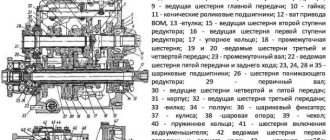
Malfunctions and causes of failure of the MTZ 82 front driving gear
Failure of the FDA operation is possible for two types of reasons: a malfunction of the FDA drive or a breakdown of the front axle mechanism itself.
Problems with the FDA drive
- Failure in the operation of the transfer case, which does not allow power to be transferred to the intermediate drive support or disrupts the switching of FDA operating modes. The breakdown can be visually determined if there is no rotation of the cardan shaft connecting the transfer case to the intermediate support with the forced FDA operating mode turned on and the axle final drive cardan disconnected. The reasons are: a malfunction of the unit or incorrect adjustment of the drive for engaging the FDA operating modes, wear or contamination of the transfer case mechanism.
- Failure or incorrect adjustment of the friction clutch of the intermediate support of the FDA drive is accompanied by overheating of the unit and squeezing out the boiled lubricant from the support body through the seals. In this case, the transmission of torque from the support to the FDA main gear is disrupted or completely absent. This can usually be determined when driving under load with the axle drive engaged.
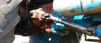
Drive transmission units for the front axle MTZ 82
Causes of FDA failures
A common cause of failures in FDA operation is wear or destruction of mechanism parts. The main factors influencing the wear rate are:
- Insufficient lubrication of mechanisms due to improper control of the oil level in the bridge housings, ignoring leaks and the ingress of abrasive contaminants into damaged seals of the unit.
- Incorrect adjustment of clearances in the meshing of gear pairs and races of bearings of rotation supports in the mechanism;
- Excessive traction loads and weight loads on the front axle, which negatively affect the axle mechanism.
So, to prevent breakdowns, traction and sudden dynamic loads on the FDA are limited by setting the activation of the friction clutch of the intermediate drive support within the range of 400 - 800 N.m. And also, according to the manufacturer’s operational requirements, for normal operation of the universal portal FDA, the additional load on the front axle of the MTZ 82 tractor should not exceed 800 kg.
The disadvantage of the MTZ 82 FDA is the large number of interfaces with seals in the bridge design. Due to this feature, one of the main diseases of the unit is lubricant leakage. As a result, the upper bevel pairs of the final drive suffer from frequent breakdowns.
Common FDA failures
Common symptoms of bridge failure are overheating of the unit housings, jerking during bridge operation, noise and grinding noise in the mechanism.
Malfunction of the main drive of the bridge
Accompanied by a hum in the operation of the gearbox and heating of the housing above 60°C (checked if it is impossible to touch the hand for a long time). The reasons are violation of the permissible clearances in the rotation bearings, engagement of the main gears and differential as a result of wear of the mechanism or incorrect adjustment. An indirect reason affecting the operation and condition of the main pair of FDA gears is the condition of the articulated joints of the cardan shafts and the total axial play of the shafts in the drive units, which creates axial runout on the FDA drive gear.
Malfunction of the axle differential
Accompanied by noise during operation and overheating of the housing. The reasons are also wear and tear of the assembly parts. The absence of automatic differential locking indicates wear of the friction discs of the locking clutches built into the unit housing. If the mechanism is not lubricated and the differential is overheated, the locking clutches may jam as a result of the disks welding together.
Break in transmission of torque from the tractor axle shafts to the vertical shafts of the final drives
The causes of the problem are the painting of the teeth of the bevel upper pair of final drive gears, jamming of the vertical shaft bearings as a result of insufficient lubrication, wear of the splines in the lower part of the vertical shaft or its destruction. A break in the vertical shaft indicates unacceptable wear in the pivot pair—the sleeve and the pivot tube. Check the transmission of rotation from the axle shafts to the side parts, observing through the open hatch of the upper bevel pair, while rotating the shank of the drive gear of the main drive of the bridge.
Jamming of the kingpin in the final drive of the FDA
Accompanied by the inability to turn the steered wheels. The reasons are insufficient lubrication of the “pivot sleeve - pivot pipe” pair, as well as unacceptable wear of the pair and breakage of the pivot pipe flange.
Malfunction of the lower bevel pair in the final drive
It occurs when the bearings wear out and the gaps in the races increase on the axis of rotation of the flange for mounting the wheel, where the axial play provokes beating in the toothed pair of gears, disrupting normal engagement.
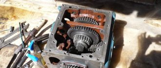
How to disassemble the MTZ-80 box
Depending on the external signs of a malfunction, the gearbox must be partially disassembled or completely dismantled. The sequence of actions for complete dismantling of the MTZ gearbox in the repair scheme described in the instructions for the tractor provides the following steps:
- transmission oil drain;
- disconnecting the box assembly from the tractor body;
- disassembling the gearbox.
If a number of transmission , you can disassemble without complete dismantling; this method is provided for unclear gear shifting, when at the first stage it is enough to dismantle the transmission control knob and check the condition of the unit.
Disassembling the MTZ-80 gearbox lever
You can check the suitability of the shift knob for further use without dismantling the gearbox, for which you need to perform the following steps:
- remove the lever by first removing the floor and disassembling the hinge socket;
- remove the plate with forks, visually determine which of them require replacement;
- inspect the suitability of the gear shift knob for further use;
- if the forks are bent and loose, and their working sides are not parallel, it is necessary to disassemble this unit and replace the worn parts.
Such repairs can eliminate only part of the possible problems associated with poor engagement and gear shifting. A complete inspection of the unit requires complete disassembly of the gearbox.
Disassembly procedure
In addition to keys and screwdrivers, the following fittings are required to remove the tractor gear shift mechanism:
- puller;
- hammer;
- metalworker's beard (beater);
- bronze knockout.
After disconnecting the assembly from the body and dismantling the plug block, you should:
- remove the retaining ring and gear from the input shaft, then remove the second ring and dismantle the bushing and gear No. 4;
- Having previously knocked out the pin, remove the internal PTO drive shaft (power take-off shaft);
- Having unscrewed the bolts and removed the socket, remove the second range drive gear complete with the cup and bearings from the housing;
- remove the input shaft to facilitate disassembly of a manual transmission operating according to the scheme (9F+2R);
- remove the intermediate shaft;
- remove the secondary shaft;
- prepare to remove the reverse and low gear shaft by removing the retaining ring and bearings;
- remove the reverse and low gear shaft from the housing;
- press out the bearing cup.
After removing the shafts from the gearbox, remove the gears from them and disassemble the remaining parts, removed entirely.
Defects of gearbox parts
After complete disassembly of the transmission, it is necessary to visually inspect all components and make a decision on their suitability for further use. In order not to miss metal defects, it is recommended to wash the components in kerosene or diesel fuel and dry them before inspection.
Recommendations for rejecting box elements:
- The housing must be replaced if cracks are detected.
- It is necessary to replace with new broken glasses in the body of the box.
- Instead of bent forks, as well as with non-parallel cheeks, new ones should be installed.
- Bearings should be checked by rotating the outer race relative to the inner race.
- You cannot install a gearshift lever with a worn tip.
You can begin installing the gearbox only after checking all the parts and obtaining new ones to replace those unsuitable for use.
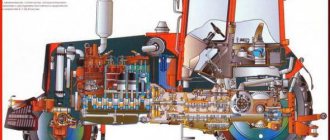
Tractor disassembly
The basis of all tractor mechanisms is a semi-frame frame. It is formed by a front semi-frame for installing a diesel engine, connected by transmission units. That is why disassembling the tractor into separate units involves disconnecting the frame and removing the necessary mechanisms.
The semi-frame is an important technical component of many agricultural machines. In a tractor, it replaces a spring, in other words, it is on the half-frame that the main part of the body rests. The chassis serves as a support for the “skeleton” of the tractor, thanks to which it can move. The semi-frame frame combines all the load-bearing prefabricated components of the tractor into a single mechanism.
The half-frame consists of a metal beam, two spars on the sides (right and left), made of rolled sheets. The rear part is secured with special brackets connecting the half-frame to the clutch housing.
The front beam, which is bolted to the spar, holds a number of parts: front engine mounts, water and oil radiators, engine shutters, power steering housing. The beam has small holes into which a steel sleeve is pressed. It is installed to secure the swing axis of the front axle.
The frame of the semi-frame requires constant monitoring, like springs; it cannot be allowed to crack or sag; the condition of the fastening elements should be monitored very closely.
For any technical work you will need special tools. Especially when it comes to unusual vehicles like tractors. If there are many universal tools for cars, then to work with a tractor you will need many separate “chips”. Some devices can jack up the car, others can separate parts, roll out certain parts, remove them, or install them back.
Units can be dismantled or assembled using special clamps and traverses using a crane beam, electric or manual hoist.
Despite the fact that the Minsk plant built the MT 80, 81 model practically “for centuries,” natural wear and tear of parts is not uncommon. Why is it better to identify problem areas locally? For all parts there is such a definition as “running in” - the ideal combination of parts installed by the manufacturer. If the unit is reassembled, the running-in is disrupted, reducing the service life of the parts. Therefore, if you constantly disassemble and reassemble mechanisms, the wear rate of external and internal components will increase. Therefore, before getting to the bottom of the problem, some preparatory work should be done.
- It is very important to conduct an external inspection. Externally, surface defects are revealed: chips, cracks, dents. Some may be purely cosmetic, while others may affect the performance of the tractor.
- If an external inspection reveals elements that need to be removed to further eliminate damage, the housing elements are dismantled.
- Some parts are for replacement, some are for troubleshooting.
- Troubleshooting is done only after washing. Clean parts show wear, chips, and cracks much better.
- Tractors are designed in such a way that some parts can be removed without much disassembly. Such spare parts include, for example, an air cleaner, a centrifugal oil purifier, a pump, a hydraulic distributor, a starter, a compressor, a transfer case, an intermediate driveshaft support, a front axle, and a drive axle.
To remove the remaining parts, it is necessary to dismantle the side tails or cabin, electrical fittings, and hydraulic units.
It is necessary to remove the cab when repairs are needed to the clutch housing, reduction gearbox, gearbox, rear axle and its drive. In this case, you can immediately remove the entire cabin assembly.
- The rear radiator trim is removed and the control rods are disconnected.
- Next, you need to remove the brake valve springs, brake pedal levers, disconnect, remove the clutch and brake pedals, disconnect the pipes that supply heat, dismantle the brackets and cab mounts.
- We disconnect the wires connecting the battery to the starter, the electric drive to the instrument panel, remove the handles of the reduction gear control levers and the gearbox.
- The internal tachometer cable, signal and headlight pads are disconnected.
- The general rubber mat and floor box are dismantled.
- The fastening bolts that secure the cabin are removed, and the floor is removed.
- Finally, at the final stage of disassembly, the terminals are removed, the batteries are pulled out, and the “ground” is disconnected from the cabin. The body, completely deprived of power, is dismantled.
Dismantling the cabin is the largest disassembly that is possible when repairing the MTZ 80, 82 tractor. The convenience of these models is based on the fact that to repair certain parts it is enough to disassemble only part of the accompanying mechanisms. For example, to repair a clutch, the half-frame and diesel engine are disconnected from the clutch housing. All mechanisms are assembled in the reverse order from disassembly.
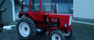
MTZ 80, 82 is equipped with a four-cylinder, four-stroke diesel engine of the Minsk Motor Plant of the D 240 series with liquid cooling. The working volume of the power unit is at least 4.75 liters, and the power is only 75 horsepower. For trucks, we can say that this number of “horses” is quite small, but the internal combustion engines are so revving that they allow not only the tractor itself to develop a decent speed, but also to additionally pull the trailer. In addition to good technical characteristics, we can say that the motors of the D 240 line are very durable, because even today you can find cars with engines made entirely of analog spare parts.
Today, the Minsk Tractor Plant has a good line of credit from China and the support of a local Belarusian bank, so production continues to actively develop. The modernization of the plant consists of focusing primarily on energy-rich tractors, which are produced in large volumes at the plants of European competitors such as Volvo. The plant's line of equipment includes metal-cutting machines, forging and pressing equipment, woodworking machines, foundries, and lifting and transport mechanisms.
The main buyer of Belarus tractors is still the Russian Federation. For domestic agriculture, 66% of working equipment are vehicles with a capacity of up to 100 horsepower. Within this segment, more than 95% of the equipment is occupied by machines produced by the MTZ plant. In addition to Russia, Belarus exports its tractors to foreign countries.
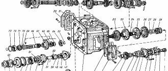
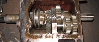
Box MTZ-80 assembly diagram
To eliminate problems when assembling the box of tractors of the MTZ-80/82 family, it is disassembled in a sequence that, when done in the reverse order, will allow you to obtain a technically complex unit without any problems. After discarding unsuitable parts and obtaining new ones, you should check that all bushings, gears and other parts comply with the standard dimensions specified by the manufacturer.
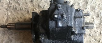
Box MTZ-80.
Gearbox bearings: type, dimensions, bearing numbers
The transmission of MTZ tractors uses several dozen standard sizes of these components. Most of them are single-row ball or needle type. The most popular sizes are also used in other components of agricultural and road machinery.
The table shows the range of common bearings used in gearbox assembly.
| Size | Manufacturer's code | Purpose in gearbox |
| 40x80x18 | 208 | power take-off shaft supports, 1st gear shaft, input shaft |
| 45x85x19 | 209 | rear power take-off shaft |
| 50x90x20 | 210 | PTO, input shaft |
| 30x72x19 | 306 | included in transfer case |
| 40x90x23 | 50308 | 1st gear and reverse shaft |
For most components used in Russia and Belarus, you can select imported, most often Chinese, analogues of similar sizes.
Assembly procedure step by step
When assembling, the following rules must be observed:
- lubricate all mounting sockets with machine oil;
- install bearings to the bottom of the seats;
- All adjusting shims removed during dismantling must be installed in their places or replaced with new ones.
Manufacturer's recommendations for tightening torque must be followed.
Step-by-step installation procedure:
- Installation of the secondary shaft, connection with the driven gear of the first gear of the gearbox. It is necessary to strengthen the bearings and check the turning torque. The main gear gear is put on the same shaft.
- Assemble the middle shaft by installing the intermediate gear on it. Check the gaps (the norm is 0.03-0.05 mm).
- Having placed all the elements of the box in their places, assemble the housing, check the joining of the planes, glue new gaskets and connect them to the rear axle and clutch housings.
Adjustments of the FDA main gearbox
Since the main pair of gears operates under conditions of significant axial loads, it is recommended to install bearings without clearance with preload in races of 0.02 - 0.05 mm. This setting ensures stable engagement in the gears and allows you to delay the appearance of gaps as a result of the production of parts. Bearings, with this setting, work due to the elasticity of the metal in the cages.
Adjusting the axial clearance in the drive gear bearings
Elimination of the gap in the bearings of the drive gear is carried out by tightening the nut on the threaded end of the shaft. The appearance of axial clearance provokes runout and subsequent destruction of the seal. If, after maximum tightening, there is still axial play, then reduce the thickness of the adjusting bushings by grinding the drive gear bearings installed between the races. Reducing the size of the bushings by the amount of play + 0.05 mm will allow you to tighten the shank nut and eliminate play in the cages with interference. The size of the backlash is determined by an indicator attached to the glass and the gear itself. Tightening is carried out while simultaneously rotating the shaft so that the bearing rollers take their place in the cages. A slight heating of the drive gear housing after eliminating the backlash is allowed, no higher than 60°C.
Checking the axial clearance in the bearings of the drive gear of the FDA main drive
Adjusting the differential bearing clearance
The check is carried out by placing the mount against the axle body and the end part of the driven gear. Diagnosis is carried out every 3000 hours, having previously checked the tightness of the connecting flanges of the axle housing and axle housings. If play is detected, reduce the number of adjusting shims between the connecting flanges of the housing and the axle cover (axle housing) by the amount of play or more by 0.05 mm from the diagnosed gap. In correctly adjusted bearings, the interference should be in the range of 0.01 - 0.1 mm.
Lateral clearance of main pair engagement
It should be noted right away that the adjustment of the engagement of the main pair is carried out only initially when it is completely replaced or the bearings of the axle housing, differential housings, and bearings in the drive gear housing are replaced. Adjusting worn gears is prohibited, since such adjustment will disrupt the organic engagement of the gears, shift the contact patch of the teeth and lead to rapid wear or jamming of the pair. It is also prohibited to install disassembled pairs or replace individual gears in a pair, that is, replacement is carried out strictly with the pair included in the manufacturer’s kit. Reconfiguration is carried out if a lateral gap in the engagement is diagnosed above 1.2-1.5 mm of the new main pair, which is a consequence of improper assembly.
Checking the clearance in the meshing of the final drive gears
The clearance in the meshing of the main pair gears is adjusted only if there are no axial clearances in the drive gear bearings and differential bearings. Adjustment is carried out by installing shims. The position of the drive gear is regulated by spacers installed under the flange of the cup along with the fastening to the axle body. The driven gear is aligned by selecting shims between the differential housing and the end of the driven gear mounted on the splines.
Setting the tooth contact of the main gear pair
After the adjustment has been made, check the contact patch in the meshing of the teeth. Correct setting shows that the entire length of the tooth is involved in the engagement. To check, several gear teeth are painted with a thin layer of paint, the drive gear cup is installed, and the gear teeth are rolled several times in both directions. Afterwards, press out the cup with the drive gear and inspect the contact patch.
The correct stain should be located closer to the narrow end of the tooth, occupying an area of at least 50% of the length and width of the tooth (Figure a ). If the contact patch does not match, adjustments must be made.
- If the spot is located on the top of the tooth, you need to bring the drive gear closer to the driven gear by reducing the number of gaskets between the cup flange and the bridge body (option b ).
- If the spot is located too low at the base of the tooth, the number of spacers between the cup and the body is increased, thus moving the drive gear away from the driven gear (option c ).
- If the spot is shifted closer to the narrow edge of the tooth, you need to move the driven gear away from the drive gear, reducing the thickness of the shim package between the differential housing and the driven gear ( g ).
- If the spot is displaced closer to the wide edge of the tooth, you need to bring the driven gear closer to the drive gear, increasing the thickness of the spacer package ( d ).
gear tooth contact options