Tractor T-40 - repair of the front axle is carried out as follows:
- Disconnect the steering linkage.
- Remove the steering axle levers.
- Release the stepladders and remove the springs.
- Remove the caps, front axle suspension hubs and brake drum.
- Disassemble the brake mechanism.
- The protective brake discs are disconnected from the axle flanges.
- The pin stoppers are knocked out and the axle is disconnected from the axle.
- Repair the side part or replace worn parts.
- Reassemble the front drive axle, performing all steps in reverse order.
The cause of the breakdown may be deflection of the front axle. Therefore, to determine such a defect you need:
- Insert the rods into the hole located under the kingpin.
- Install prisms on the spring mounting area.
- Place a special square.
- From the gap between the square and the prism, determine the magnitude and direction of the deflection.
The axle should be adjusted under a press in a cold state, because heating can cause disruption of its heat treatment.
REAR AXLE REPAIR
The rear axle structure of the T-40 tractor includes:
- gear housing;
- a flange that relates to the cardan drive;
- final drive gears;
- self-locking center differential.
During maintenance and repairs, the following must be done:
- Drain the oil fluid from the gearbox.
- Disconnect the driveshaft.
- Remove the axle shafts.
- Remove the rear wheels and brake drum mechanism.
- Unscrew the mounting bolts that connect the gearbox and rear axle.
- Remove seals, flanges, bearings and satellites.
- Inspect all parts for damage and wear.
Procedure for assembling the rear axle gearbox:
- Attach the adjusting washer to the drive gear.
- Attach the spacer, bearings and flange.
- Tighten the locknut.
- Install the driven gear into the differential housing.
- Adjust the backlash.
- Tighten all mounting nuts and bolts.
LOCK REPAIR
In order to repair the locking mechanism, you need:
- Set the gear shift knob to neutral.
- Release the main clutch pedal, i.e. the clutch must be engaged.
- Unpin the fork pin and remove it from the locking mechanism lever.
- Move the lever to its extreme position, which will correspond to the engaged clutch.
- Unscrew the plug and disconnect it from the rod.
- Adjust the locking mechanism.
- Reinstall the fork pin and secure it with a cotter pin.
In order to lubricate all the parts of this mechanism, it is necessary to spray the oil liquid over the vehicle transmission housing.
The differential lock is installed as follows:
- The tractor is installed on a special platform.
- Unscrew the wheels.
- Remove the brake drum mechanisms.
- The axle shafts, driveshaft, and gearboxes are adjusted and stretched.
- Lock and install all parts in reverse order.
REPAIR OF BRAKE BANDS
Before replacing the brake bands on the T-40, you need to remove the worn part:
- Remove the fuel fluid container.
- Remove the front and rear floor panels.
- Remove the top covers and rear hatches.
- Disconnect the traction mechanism from the brake lever.
- Unscrew the adjusting nut.
- Remove the lever with the rollers from the bracket.
- Disconnect the brake band.
- Unscrew the mounting bolts from the inside of the housing.
- Remove the bracket.
- Pull the brake bands towards the rear using the upper end.
- Unscrew the bolts that connect the upper and lower parts of the tapes.
- Remove the upper part of the brake band from the onboard friction drum.
- Rotate the bottom of the belt around the drum and pull it out.
- Remove the brake spring and rod from the lever.
- Unscrew the outer arm bolt and remove it from the shaft.
- Find the key. There is a pawl installed on the key, it needs to be knocked out.
- Knock out the roller along with the plug.
- Remove the lever and ring.
- Replace the brake band and install all mechanisms back.
Gearbox device
In the design of the T-40 tractor, a gearbox is used to change the direction of movement, select speed and perform operations. The design of the box is represented by the following elements:
- creeper;
- reverse mechanism with bevel gear;
- locking device;
- special shafts, gears with a switching mechanism;
- main gear with a differential locking device.
- Speed reducer. The device is intended, instead of a transfer case, to create an additional number of reduced speeds for the T-40, as well as to increase the number of aggregated equipment when performing various works. The creeper design consists of a gear transmission with external and internal gearing, which, when interacting with each other, form a reduced gear ratio (2.75), which is transmitted to the T-40 driven shaft.
- Reverse. A reverse mechanism with a special gear is designed to provide an additional number of speeds in the box for reversing. The design is a gearbox, the principle of which is to change the meshing gears in a bevel gear, which changes the direction and speed of movement of the driven shaft.
- Special shafts and gears, switching mechanism. Designed to obtain movement speed or change direction. The box contains input and drive shafts, as well as gears. The required gear is obtained by moving a given movable gear to engage it with a stationary one located on another shaft. The shift mechanism is designed using special shift shafts on which the forks are mounted. The shafts are moved using a shift lever, while the forks move the movable gears.
- Gear blocking device. The device is designed to prevent incomplete engagement of gears in the gearbox, as well as spontaneous disengagement. The main element is a special shaft for blocking and clamps. When the required gear is engaged, the locking shaft moves in parallel to the required gear and when the teeth match, the clamps secure the connection.
- Main gear with differential locking device. Used to transmit torque from the engine to the drive wheels, it consists of two spur gears. The differential locking device is designed to obtain the same speed of rotation of the right and left wheels of the tractor.
Tractor T-40
T-40 tractor brakes - adjustment and repair
Dry band brakes are installed on the T-40 tractor to provide braking when moving. The brakes are equipped with two tightening ends, a connecting bar for general locking and separate control. The lever, connected by a rod to the brake pedal, is mounted on an axis on the outside of the sleeve.
Adjusting the T-40 brakes
With prolonged use of the brakes, the linings gradually wear out, as a result of which the pedal travel increases, which worsens braking. In this case, it is necessary to adjust the pedal travel in the following order:
Selecting transmission oil
During long-term operation of a vehicle with a GAZ-3307 gearbox, the driver may encounter a problem such as oil leakage from the gearbox. In some cases, this may be due to the fact that the fastening bolts are loose, the oil seal has worn out, or there is a crack in the crankcase. Deformed parts must be replaced and new oil added.
Replacing transmission fuel is a type of gearbox repair. What kind of oil should be poured into a manual gearbox on a GAZ-3307? It is recommended to add TAP-15v transmission fluid to the gearbox; about 6 liters are required. The replacement frequency is 60,000 km.
Thus, the GAZ-3307 truck has good cross-country ability and is equipped with a reliable manual transmission, which is designed for a long service life. It should be periodically maintained and the transmission oil changed to reduce the risk of serious breakdowns in the automotive system.
GAZ trucks use a classic manual transmission, and the gearbox has undergone almost no changes over the past half century. The gear selection mechanism plays an important role in this gearbox - read the article about this transmission unit, its role, design, operation and repair.
POWER REPAIR
Troubleshooting power steering (power steering):
- Install the screw assembly with the front nut and front cover into the piston part so that the pin moves to the forward position.
- Turn the piston.
- Install a rod into the end hole of the nut.
- Using a screwdriver, turn the nut until it is completely secured with the bolt.
- Connect a pressure gauge to the steering column pressure line.
- Unscrew the plug.
- Place a stop between the bipod and the front side of the beam.
- Unscrew the cap and lock nut.
- Start the engine.
- Set the maximum number of crankshaft revolutions.
- While rotating the bipod, adjust the pressure level of oil fluid bypass through the safety valves.
- Tighten the locknut and cap.
- Replace the conical plug.
In order to avoid malfunctions of the hydraulic power steering, you need to periodically check the steering wheel play and tighten all nuts and bolts.
How to adjust the clutch
Procedure for adjusting the clutch:
- Open the hatch of the clutch basket.
- Undo the cotter pin and pull out the axial part of the traction mechanism fork.
- Remove the fork from the lever.
- When screwing on the fork, set the rod length so that when connecting the fork to the handle, the gap between the ends of the levers and the release bearings is 4 mm.
- Install and tighten the axial part of the fork.
- Close the hatch in the basket along with the lid.
If this mechanism cannot be adjusted by increasing the length of the rod, then the following can be done:
- Open the top hatch and undo the nuts.
- Unscrew the adjusting bolts.
- Move all levers to the forward position.
- Connect the clutch lever and the traction fork.
- Cotter the axle.
- Use feeler gauges to adjust the gap.
Tractor T-40
T-40 tractor brakes - adjustment and repair
Dry band brakes are installed on the T-40 tractor to provide braking when moving. The brakes are equipped with two tightening ends, a connecting bar for general locking and separate control. The lever, connected by a rod to the brake pedal, is mounted on an axis on the outside of the sleeve.
Adjusting the T-40 brakes
With prolonged use of the brakes, the linings gradually wear out, as a result of which the pedal travel increases, which worsens braking. In this case, it is necessary to adjust the pedal travel in the following order:
1. Unscrew the bolts and remove the sleeve hatch cover;
2. Unscrew the lock nut and then tighten the link nut until the full pedal stroke is no more than 150 millimeters;
3. Secure the nut in this position with a locknut and make sure that the brakes are adjusted correctly.
When the brake is correctly adjusted, the outer lever of the left brake should move 8 degrees back vertically, and the right one should move 10 degrees back. In order to obtain simultaneous braking of both wheels of the T-40, it is necessary to increase the travel of the right brake pedal by 10-15 mm relative to the left.
The free play of the brake pedals is adjusted simultaneously, with the pneumatic system turned off, so that when they are blocked, both rear wheels are simultaneously braked. When adjusting, the pedals must be in their rearmost position.
In order to ensure that there is a uniform gap between the drum and the brake band, after each adjustment the position of the brake band should be adjusted, for which:
— loosen the locknut of the adjusting screw located in the lower part of the brake housing and tighten the screw until it stops;
— then unscrew it ¾ of a turn and secure it with a lock nut.
Brake diagram of the T-40 tractor: 1 - lever; 2 - spherical washer; 3 - lock nut; 4, 12 and 13 - bolts; 5 — lock washer; 6 — washer; 7 — tape finger; 8 — tape; 9 — brake drum; 10 — lever axis; 11 — sleeve cover; 14 — sleeve; 15 — adjusting screw; 16 - lock nut.
T-40 tractor brake repair
During long-term operation, the brake linings may become oily, as a result of which they must be washed with kerosene. Remove the hatch cover and fill in 1.5-2 liters of kerosene. Close the hatch cover. Wash the brake band while driving the tractor forward and backward. After stopping, drain the kerosene by unscrewing the adjusting screw. Next, after washing, adjust the position of the tape with the screw. The oil content in the hose body can be determined by unscrewing the adjusting screw.
If the brake band becomes oily again, it is necessary to disassemble the brake and replace the O-ring or seals. To increase the service life of the brake mechanism of the T-40 tractor, you should follow simple rules:
— do not allow braking without the clutch disengaged;
— do not keep your foot on the brake pedals while the tractor is moving.
Before starting to operate the tractor, it is necessary to ensure that the brakes are working properly and, if necessary, adjust them. In case of disassembling the brake control, it is necessary to correctly install the servo spring, which reduces the force on the pedal.
T-40 engine
Engine structure of the T-40 tractor: piston, crankshaft, cylinders
Power transmission
Design and operation of the power transmission of the T-40 tractor
Supply system
Design of the T-40 tractor power system: nozzles, fuel injection pump, etc.
Electrical equipment
Electrical equipment T-40: diagrams and device.
Hydraulics
Hydraulic system: malfunctions and repairs.
Tractor T-40 - design, operation and repair
To watch online, click on the video ⤵
t-40 am, how to replace brake bands without removing the side Read more
Replacing the brake band. LTZ.T-40AM. More details
Adjusting Brakes on #LTZ_60AV / T-40 In detail. #Maksim_TechnikPRO Read more
Brakes on the T-40 tractor Read more
replacement of the T40 brake band without removing the onboard REAL Read more
They removed the side panel and there it was HORRIBLE. tractor T-40AM More details
Replacing T-25 tractor brake bands More details
Repair of axle shaft with brake drum onboard T-40AM. More details
Brake repair on T-40 Read more
Replacing brake bands on T-25. (Replacement of brake bands on T-25.) More details
Air brakes on T-40AM More details
Restoration (repair) of the longitudinal thrust of the T-40 linkage More details
Changing the Oil in Onboard and Gearbox T 40 #Maksim_TechnikPRO Read more
T-40AM. D-144. Flushing the engine with diesel fuel. More details
T-40AM. Power shaft (Primary) More details
Click, and there is no more clutch. Belt in the cold! T-40AM Read more
T-40 engine on T-25 Read more
Why doesn't the hydraulics hold the hitch, and why doesn't the hydraulics lift? Read more
We are testing a Mercedes turbine on a tractor! (Turbo tractor, part Read more
IF THE TRACTOR SMOKES
If a tractor smokes, this may be due to:
- incorrect adjustment of the working fluid supply;
- motor overload;
- incorrect installation of the piston part;
- dirty air purifier;
- small advance angle of the fuel injection system;
- damaged injectors.
In these cases, engine repair using spare parts is required, and in some situations, overhaul.
If the smoke is black, it is recommended to reduce the load on the power unit or switch to first or second gear. It is also worth checking the nozzle holes of the spray mechanism with a needle, rinsing it, and if necessary, replacing it.
When white smoke pours out, you need to grind the valves or replace the heads of the cylindrical elements. The cause of white smoke may be water getting into the diesel fuel; in this case, it is necessary to drain the fuel fluid and add new one.
Installing the fuel pump and adjusting the ignition
Installation of a high pressure fuel pump (HPFP):
- Determine the position of the wide flange slot on the fuel pump.
- Rotate the pump element shaft so that the wide part of the spline bushing cavity is opposite the wide flange spline.
- Using a mounting journal, insert the pump into the gear hub.
- Install the pump mechanism.
- Screw the high and low pressure pump with bolts.
- Warm up the engine.
- Start the power unit at idle speed.
- Pull up the tray.
- Loosen the fixing nut.
- Slowly turn the distributor in different directions.
- At maximum engine speed, try pressing the gas pedal.
- If, when pressed sharply, there are no interruptions, pops or shots, then the ignition on the tractor is installed.
- From this position, rotate the camshaft housing 2-3° clockwise.
- Clamp the locking element.
Tractor T-40
T-40 tractor brakes - adjustment and repair
Dry band brakes are installed on the T-40 tractor to provide braking when moving. The brakes are equipped with two tightening ends, a connecting bar for general locking and separate control. The lever, connected by a rod to the brake pedal, is mounted on an axis on the outside of the sleeve.
Adjusting the T-40 brakes
With prolonged use of the brakes, the linings gradually wear out, as a result of which the pedal travel increases, which worsens braking. In this case, it is necessary to adjust the pedal travel in the following order:
1. Unscrew the bolts and remove the sleeve hatch cover;
2. Unscrew the lock nut and then tighten the link nut until the full pedal stroke is no more than 150 millimeters;
3. Secure the nut in this position with a locknut and make sure that the brakes are adjusted correctly.
When the brake is correctly adjusted, the outer lever of the left brake should move 8 degrees back vertically, and the right one should move 10 degrees back. In order to obtain simultaneous braking of both wheels of the T-40, it is necessary to increase the travel of the right brake pedal by 10-15 mm relative to the left.
The free play of the brake pedals is adjusted simultaneously, with the pneumatic system turned off, so that when they are blocked, both rear wheels are simultaneously braked. When adjusting, the pedals must be in their rearmost position.
In order to ensure that there is a uniform gap between the drum and the brake band, after each adjustment the position of the brake band should be adjusted, for which:
— loosen the locknut of the adjusting screw located in the lower part of the brake housing and tighten the screw until it stops;
— then unscrew it ¾ of a turn and secure it with a lock nut.
Brake diagram of the T-40 tractor: 1 - lever; 2 - spherical washer; 3 - lock nut; 4, 12 and 13 - bolts; 5 — lock washer; 6 — washer; 7 — tape finger; 8 — tape; 9 — brake drum; 10 — lever axis; 11 — sleeve cover; 14 — sleeve; 15 — adjusting screw; 16 - lock nut.
T-40 tractor brake repair
During long-term operation, the brake linings may become oily, as a result of which they must be washed with kerosene. Remove the hatch cover and fill in 1.5-2 liters of kerosene. Close the hatch cover. Wash the brake band while driving the tractor forward and backward. After stopping, drain the kerosene by unscrewing the adjusting screw. Next, after washing, adjust the position of the tape with the screw. The oil content in the hose body can be determined by unscrewing the adjusting screw.
If the brake band becomes oily again, it is necessary to disassemble the brake and replace the O-ring or seals. To increase the service life of the brake mechanism of the T-40 tractor, you should follow simple rules:
— do not allow braking without the clutch disengaged;
— do not keep your foot on the brake pedals while the tractor is moving.
Before starting to operate the tractor, it is necessary to ensure that the brakes are working properly and, if necessary, adjust them. In case of disassembling the brake control, it is necessary to correctly install the servo spring, which reduces the force on the pedal.
T-40 engine
Engine structure of the T-40 tractor: piston, crankshaft, cylinders
Power transmission
Design and operation of the power transmission of the T-40 tractor
Supply system
Design of the T-40 tractor power system: nozzles, fuel injection pump, etc.
Electrical equipment
Electrical equipment T-40: diagrams and device.
Device, diagrams, repair
Front drive axle of the T-40 tractor - design and repair
Front axle device
The front drive axle of the T-40 AM and T-40 ANM tractors is used to increase traction forces and increase cross-country ability on moist soils and in off-road conditions. The front axle consists of a transfer case, differential, main and final gears and suspension.
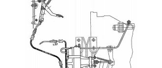
Diagram of the T-40 front axle: 1 - transfer case housing; 2 - plug; 3 - gear; 4, 24 — ball bearings: 5 — front cover; 6 — transfer case shaft; 7 — drive shaft of the front drive axle; 8 — main gear drive shaft; 9 - drive gear; 10 - glass; 11 — driven gear; 12 — adjusting shims; 13 - wedge; 14 — axle shaft; 15 — brake washer; 16 — bridge body; 17 — pawl axis; 18 - dog; 19 — differential housing cover; 20 — shield; 21 — final drive; 22 — front wheel suspension; 23 — cardan; 25 — splined holder; 26 — differential housing; 27 - pin; 28 - sleeve.
Front axle final drive
The main gear consists of a pair of bevel gears with a circular tooth. The drive gear is mounted in a cup on two ball bearings. The driven gear is part of the differential and is attached to the differential housing with bolts and pins.
During operation of the front axle, it is necessary to monitor the lateral clearance in the engagement of the teeth of the main gear. If noise or other malfunctions occur, it is necessary to check the mesh clearance or axial play of the drive gear. Due to tooth wear, an increase in the lateral clearance in the meshing is permissible up to 2 millimeters. If the gap increases due to wear of the bearing tracks, they must be replaced with new ones. The factory adjustment of the lateral clearance in the gear mesh is in the range of 0.17-0.65 mm.
Both gears are replaced simultaneously during operation and further development of their service life. When installing the sleeves, the total number of shims on both sides should be such that the differential rotates freely in the bearings by hand without any jamming or displacement.
Front axle differential
The differential allows the drive wheels to rotate at the same angular speed, which is required when driving the tractor over uneven terrain and when performing maneuvers.
The front drive axle differential design is a double-acting ratchet-type overrunning clutch. The differential consists of a housing, a splined race, a driven gear and a cover, connected to each other using four bolts. In the driven gear, cover and differential housing there are two axes each, on which a pawl is installed on a key. As the driven gear rotates, the pawls engage with the inner races by the frictional force that appears between the special patterns on the ends of the pawl axles and the surfaces of the brake washers.
Using springs, the axles are constantly pressed against the brake washers to create friction. Depending on the direction of rotation, the pawl engages with one of its ends. If the rear wheels rotate with less than 4% slip, the splined races overtake the driven gear, forcing the pawls to click along the teeth of the races. When the slipping of the rear wheels exceeds 4%, the forward movement of the tractor will decrease, while the driven gears and angular speeds of the cage will be leveled. With a subsequent increase in slipping of the rear wheels, the pawls will engage with the splined race, as a result of which torque will be transmitted from the driven gear through the splined races and axle shafts to the front wheels.