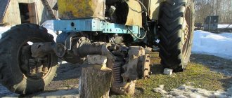
T-25 is an agricultural wheeled tractor with more than half a century of history. It is designed for cultivating light soils in gardens and greenhouses, works well with a mower and transports small loads. The first copies rolled off the assembly line in 1966. The model was produced at the Vladimir and Kharkov tractor plants in various modifications and has not lost its relevance to this day. Among the reasons for its popularity were design solutions. Among the new products used in the development of the T 25 is a gearbox, the switching pattern of which, by the way, has been improved compared to older models.
Causes and symptoms of bearing failure in manual transmissions
Bearing units in a manual transmission perform the function of rolling bearings, therefore, if the rolling bearing is faulty, there will be difficult rotation of the elements, an imbalance will appear, as well as radial and axial runout, backlash, noise, and knocking.
- The bearing hums, the noise increases when the clutch is disengaged;
- Difficulty switching gears;
- Spontaneous transmission shutdown;
- A knocking noise is heard when pressing the clutch pedal.
- Expiration of product service life;
- Poor quality ball bearing;
- Wear or runout;
- Aggressive driving style and gear shifting;
- Insufficient amount of lubricant on the bearing or its absence;
- Dirt or abrasive particles getting inside the ball bearing;
- Malfunction of adjacent components (releaser, clutch, secondary or intermediate axle).
Read more: How many points to pump wheels in winter
After removing the axle from the axle, you need to make sure that the part is faulty. To do this, check the ease of rotation of the part, and also do a visual inspection, namely, the presence of damage to the rings, cage, as well as defects in the raceway. If the product is in good condition, it is advisable to take measurements of the axial clearance and radial clearance, as shown in the video.
Video: “How the VAZ 2107 input shaft bearing hums”
Video: “Bearing play in the input shaft of the VAZ 2107 gearbox”
Caliper UAZ loaf
The brake caliper may also need repair. All components of the device are constantly exposed to the negative effects of water, brake fluid and salt. In order for the caliper to last longer and wear less, it must be regularly lubricated with special products. Nigrol or lithol cannot be used for these purposes. The lubricant must be heat-resistant. The operating parameter of the substance must be at least 180°C. The lubricant must not dissolve in water or brake fluid. Its main property is compatibility with plastic parts.
Lubricants can be divided into three types.
- Oxol consists of anti-seize high-temperature paste. It is used to lubricate brackets, metal surfaces of plates and pads to eliminate squeaks.
- A lubricant made from materials that work well with bolts, pins, and pistons.
- A universally used substance for lubricating all moving parts, both plastic and elastic.
Silicone high temperature caliper grease
Silicone high-temperature lubricants are the most popular. A car owner who is poorly versed in the assortment usually buys substances from the third group. The first thing to do before starting lubricant treatment is to check the dust cap and, if it is faulty, replace it with a new one. When processing, do not allow the paste to get on the anti-dust cuffs, otherwise they may swell. The lubricant is applied to the parts in a thin and even layer.
Tractor engine design
The engine of the machine belongs to the class of 4-cylinder, four-stroke engines with a water cooling system for the tractor.
It was created specifically for the line of these tractors at the same Minsk Tractor Plant. The operating volume of the engine is approximately 4.75 liters. Thanks to high-quality electrical equipment and a semi-separate combustion chamber, the rated engine power is 80 hp. s., and torque – 2200 rpm. The weight of the diesel engine is 428 kg. Some tractor models are additionally equipped with a pre-heater PZHB-200B. To start the machine, it is equipped with an electric starter and a carburetor starting motor. The design also includes a starter locking device, which must be used to hold the tractor in place when the engine is running. To extend the life of the engine, the manufacturer recommends inspecting and servicing it every 240 operating hours. The manufacturer does not recommend using the heater unless necessary, as this negatively affects the stability of engine torque.
Gearbox and clutch repair
The T-25 tractor gearbox does not have synchronizers, but has a doubler and reverse. There are 8 gears for forward movement and 6 reverse gears. The gearbox itself, the differential and the main gear are located in one housing, which will facilitate access to these components for repairs. Partial disassembly is possible even without removing it from the tractor.
Possible problems
- The bushing and bearing seats can quickly wear out or become damaged, which ultimately leads to a complete replacement of the crankcase casting. Try to monitor the condition of the bearings and change them on time.
- Periodic adjustment of the installation gaps of shafts, bearings and gears is required. Doing this job requires some skill and tons of patience. But when everything is adjusted, the gears shift easily and clearly, which guarantees a long service life of the box.
Parts that need to be constantly monitored in the T-25 gearbox, because... they most often fail.
- moving gears,
- bearings,
- clamps and rollers,
- gear forks,
- secondary shaft stops,
- ears of the lock washer and the retainer cover.
Under no circumstances should you pour modern synthetic gear oils with high viscosity into the gearbox. Remember that the T-25 tractor itself was developed in the middle of the last century, and lubricants then were of a completely different quality. We recommend using mineral gear oil W90 standard GL3.
Disassembling the gearbox
- Open the transmission housing and remove the bearing cover on the left, where the main shaft is located.
- Remove the power take-off shaft cover.
- To remove the cup with bearings, unscrew the clamping nut and bushing.
- To remove the reverse, remove the lock washer on the left and turn it 30 degrees. And remove the stopper from the bearing.
- Assembly is performed strictly in reverse order. When repairing the gearbox, inspect all parts that are heavily worn and replace them with new or reconditioned ones.
Clutch maintenance and repair
The clutch on the T-25 is a dry, single-plate, permanently closed clutch. In some cases, clutch slippage may occur due to improper clutch adjustment or due to oiling of the disc. Oil can get onto the disk from the hydraulic pump or from the engine through the oil seals and seals of their drives. To remove the oil, the clutch is disassembled, the driven disc is pulled out, washed in gasoline and dried.
It is important Which KUN to install on MTZ
To adjust the clutch, place the gearshift lever in neutral and remove the connecting housing cover on the left side. Turn the crankshaft with a wrench so that three clutch release levers alternately appear in the hatch. Using special plates, check the gaps between the thrust bearing and the end of each lever; it should be 2-3 mm. The difference between individual levers should not exceed 0.1 mm.
If the gap does not meet the required values, unscrew the lock nut and turn the adjusting bolt until you obtain the desired gap. After this, do not forget to tighten the locknut onto the bolt. As the friction linings wear, the gap will gradually decrease. If it decreases significantly, then when the clutch is engaged, the bearing will constantly rotate, quickly wearing out itself and the levers.
If the clutch driven disc is worn to the point that the rivet heads are visible, then the worn linings are replaced.
Lubrication of the front bearing of the clutch shaft and the lift housing is carried out only during complete disassembly of the tractor.
During operation of the tractor, oil will inevitably leak through the seals. To release it, it is recommended to periodically turn the cotter pin at the bottom of the connecting body.
Reasons for failure
Thanks to the design features of the transmission, the repair of the T-25 tractor gearbox has been simplified, but other problems have arisen that should be given close attention:
- In adjusting the installation gaps of shafts, gears, bearings, and some other parts. This adjustment is made using special metal shims of varying thickness. Painstaking work requires special skills and patience. When done correctly, gears shift accurately, without additional effort, and the gearbox itself works correctly.
- Damage or deterioration of the seats of bushings and bearings leads to the fact that over time the cast crankcase body has to be replaced. To avoid this, the condition of the bearings and other components of the assembly should be monitored.
Despite the shortcomings, the resource of the box is long, and the performance characteristics are not satisfactory. The cause of malfunctions is the wear of some parts:
- Moving gears.
- Bearings.
- Clamps and rollers.
- Gear forks, reverse.
- Secondary shaft stops.
- Lock washer lugs, retainer cover.
- Primary shaft key grooves.
When repairing the box, pay special attention to the condition of these parts.
Injection pump repair
The maximum idle speed of a diesel engine can be adjusted by changing the spring stiffness level by changing the number of its working turns.
High pressure fuel pump repair:
- Install the fuel injection pump on the stand and connect the fuel wire.
- Adjust the starting fuel supply by 50-100%.
- Unscrew the screw and set the control lever to the extreme position for maximum speed.
- Tighten the corrector screw until it stops.
- Set the required fuel supply at the rated camshaft speed by moving the housing relative to the cover.
- Adjust the start of fan operation to 10-15 rpm.
- Check the fuel supply at nominal mode.
- Test the complete shutdown of the fuel supply through the injectors.
- Adjust the pump camshaft speed.
- Unscrew the adjuster screw and adjust the fuel supply in accordance with the required engine torque reserve.
Also, fuel injection pump malfunctions can be associated with damage to the bearings. In this case you need:
- Remove the low pressure pump.
- Place a rigid rod of small diameter under the cam shaft.
- Check all parts for damage and replace if necessary.
Repair of steering column and side
Problems with the steering column may be the following:
- Increased free play of the steering wheel. In this case, it is necessary to adjust the clearance in the tapered bearings, rod joints, worm bearings and gearing. You should also tighten the nuts.
- The tractor driver is forced to apply a lot of effort to the steering wheel. This will require adjusting the valves and checking the oil pressure in the hydraulic system. It is necessary to inspect all parts for leaks and adjust the engagement.
- Vibration of wheels (equipment wobbles from side to side). This problem is solved by tightening the fastening of the assembly units and adjusting the rod joints using a lever.
The steering must be cleaned of dirt and dust, all fasteners must be tightened, and gears and bearings must be treated with special lubricant, thereby increasing the service life of the mechanism.
To lubricate the worm pair, transmission oil is used, poured into the lower housing of the steering mechanism.
In order to adjust the steering column, you need to:
- Set the front guide wheels strictly straight relative to the longitudinal axis of the tractor.
- Unscrew the bolts and remove the support washer.
- Adjust the worm gearing.
- Return the support washer and tighten the bolts.
How to bleed the brakes on a UAZ Bukhanka video
If the front brake circuit of the UAZ “loaf” is compared with the rear brake circuit, then it is easy to understand that they are the same, with one exception. The rear brake pads operate from one cylinder, while the front brake pads operate from two. This is because the front axle requires a more efficient braking system due to the greater load during braking.
All these elements are combined into one structure when the rim is cast. At the same time, convenient access to the drums is provided, since they are removable. Thanks to this, cleaning and checking them will not cause serious complications, since there is no need to remove the hubs, and accordingly, the adjustment of the wheel bearings will not be disrupted.
The famous UAZ-452, popularly called the “loaf”, has long established itself as a reliable and unpretentious car. However, every vehicle sooner or later requires maintenance, replacement of some parts, etc. Of course, you can just take your car to a service station, pay a certain amount of money and not worry about anything.
Important Technical characteristics and analogues of the DZ-180 motor grader
Do not add fluid to the brake master cylinder that is collected in a glass container during bleeding. If the brake fluid in the system is dirty, drain it and refill the system with fresh fluid. Do not press the pedal with the brake drum removed, as pressure in the hydraulic drive will force the pistons out of the wheel cylinders and fluid will flow out.
UAZ 3741 or 452, called by the people “loaf”, is the most famous creation of the Ulyanovsk Automobile and is remembered as a reliable ambulance, emergency gas service, police, water utility vehicle. She has many positive qualities. It is unpretentious in maintenance, has excellent maneuverability and endurance.
An expansion mechanism is attached to the upper part of the brake shield, and an adjustment mechanism to the lower part. Both brake pads are the same.
When the process is completed and the liquid continues to bubble, check the seals of the joints, pipes, and cylinders (main and working). Check threaded connections, change seals, gaskets, rings, and cylinder cuffs. As for replacing working cylinders, the replacement process occurs as a complex.
Engine repair
The tractor was equipped with a four-stroke, two-cylinder air-cooled diesel engine D-21, produced by the Vladimir Tractor Plant, with a power of 20 hp.
Typical problems in the operation of the T-25 tractor engine and ways to eliminate them
- The engine will not start.
- Clogged or air in fuel line. Clean, rinse and bleed the fuel line. Bleed the fuel system.
- The fuel pump is faulty. Remove the pump and send it for repair.
- Clogged or poor atomization of diesel fuel injectors. Clean the injectors.
There is a blockage in the fuel filter. Wash the coarse filter and replace the fine filter.
- Air or water has entered the fuel system. You need to either bleed the system by removing air or drain all the fuel and fill in new, high-quality fuel.
- Check the engine oil level, if it is above the maximum, drain the excess.
- Incorrect valve clearance. Adjust the gap.
- Blockages in the intercostal space of the heads and cylinders. Stop the engine, let it cool and remove all deposits and other dirt from the intercostal space.
Gearbox and clutch repair
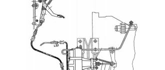
T-25 tractor clutch repair:
- Disconnect the rod from the lever by removing the pin.
- Release the clutch pedal from the action of the spring by screwing the stop bolt into the bracket and lowering the bolts to allow the bracket to move freely.
- Set the free play of the pedal on the pad to 0.4-0.45 cm.
- Place the bracket in the upper position and tighten the fastening bolts.
- Unscrew the stop bolt and return the pedal to its original position.
- Turn the lever counterclockwise until it stops.
- Adjust the length of the brake rod and connect it to the lever. After these steps, you can pin the pin and tighten the locknuts securely.
Repair of the gearbox of this tractor model:
- It is necessary to replace the bevel gears in the hydraulic distributor drive.
- Adjust the range shift and reverse locking mechanism.
The locking mechanism is adjusted as follows:
- The rod is disconnected from the locking roller lever.
- Fully depress the clutch pedal.
- Install the locking roller so that the axis of symmetry of the roller lever coincides with the pointer on the compartment cover.
- Connect the rod to the lever and check the adjustment by turning on the reverse ranges.
- Seal the pin and tighten the locknuts.
Features of the gearbox
The T 25 gearbox device was developed to simplify the maintenance and repair of the vehicle away from service centers. The designers were faced with the task of making sure that the driver could carry out repairs without removing and disassembling the entire box, which significantly reduced downtime. To do this, the manufacturing technology had to be somewhat complicated - the box was combined with a differential (a device that converts torque) and a final drive. A bevel gear was attached to the T 25 drive or input shaft, which transmitted torque from the engine flywheel at an angle of 90°. The efforts paid off - servicing the unit in the field has become easier, and its dimensions have decreased.
Gearbox T-25
Gearbox design
Essential elements:
- the input or drive shaft connected to the engine flywheel;
- a hollow intermediate shaft, inside of which the power take-off shaft is located, and the gears are adjacent to the top;
- the main shaft on which part of the gears, retarding and doubling gears are installed;
- a differential on which the gears of the axle shafts and the accelerated and decelerated series of gears are attached;
- gear shift lock (protects against damage if the clutch is not fully depressed), located on the crankcase cover.
Be sure to read: Technical characteristics of YaMZ-238 turbo
The old-style T-25 gearbox was ten-speed (six forward speeds and four reverse), later ones added two more forward speeds. Accordingly, the gear shift pattern on the T 25 tractor has also changed. The method of switching reverse and doubler remains the same. A separate lever is provided for this.
Lubricants
To lubricate the gearbox, mineral oils with a viscosity of W90 are used . T-25 is tolerant of lubricant quality, like most equipment developed in Soviet times; it is suitable for transmission oils that meet the GL-3 standard. Moreover, the use of expensive synthetic oils with low viscosity can lead to failure.
There is a special hole in the lower part of the crankcase to drain the oil. Level control and filling of new lubricant are carried out through the hole in the left wall.
Useful tips
The equipment must be used in accordance with the instructions.
In winter, operating the tractor becomes more difficult, so for stable operation of the unit it is recommended to do the following:
- Replace all summer types of lubricant with winter ones.
- Drain the fuel and rinse the tank with clean diesel fuel.
- Drain the fuel from the fuel line, replace the filters and pour a winter type of diesel into the tank, fill the system with it and completely get rid of air bubbles.
- Remove the battery and inspect it.
- Fuel must be filled through a suede or flannel filter.
- The tank must always be full. When filling, you need to make sure that no liquid gets into the fuel, because the resulting pieces of ice can clog the fuel wires and stop the supply of fuel.
- Once a day it is necessary to inspect the tank for the presence of water.
Important Terex Backhoe Loaders
In order to carry out repair work correctly, it is recommended to use the book “Repair and Maintenance Manual for the T-25 Tractor”.
Causes of breakdowns and their restoration
Problem #1: Difficulty shifting gears, inaccurate shifting.
Solution: Adjust the clearances of shafts, gears and other parts. Thanks to the above features, gearbox repair has become easier, but there is a need to regularly check the clearances. This is painstaking work that requires experience. It is carried out similarly to adjusting engine clearances - using special metal feeler gauges and gaskets of different thicknesses.
Tractor gearbox diagram
Problem No. 2 : Knocks out gears when working with heavy equipment (plow, blade).
Solution : Adjust the clamp and check the tightness of the fixing bolts.
Problem #3: Oil leak.
Solution: Replace the input shaft oil seal.
General repair recommendations:
- Before starting repair work, open the crankcase housing and remove the bearing cover. It is located to the left of the main shaft. Then remove the power take-off shaft cover located on the right.
- In order to remove the cup with bearings, you need to unscrew the clamping pin and the spacer sleeve.
- To remove the reverse, you need to remove the lock washer, for which you need to turn it 30°, after which it will be easy to remove the stopper from the bearing.
- The question often arises of how to remove the input shaft from the T 25 tractor. The safest way is not to knock it out, but to pull it out by screwing two bolts into the holes under the power take-off shaft.
Be sure to read: Technical characteristics of the UD-2 engine
Assembly is carried out in the reverse order, if necessary, replacing worn parts.
Gearbox parameters and design
T-40 tractors were equipped with eight-speed manual transmissions. The T 40 tractor gearbox diagram includes the following elements:
- Speed reducer. Ensures tractor operation at reduced speeds, which is required when using certain types of agricultural equipment. It is a gear transmission connected to the reverse bevel gear and to the creeper shaft through splines. It is installed on the left side of the tractor in the bore under the reverse bevel gear housing.
- Reverse with bevel gear. Provides reverse movement. It is a gearbox that switches meshing gears in a bevel gear. As a result, a change in the direction and speed of movement of the driven shaft is ensured.
- The bevel gear also transmits torque and direction of rotation from the engine to the input shaft and speed reducer. The drive gear is located in the front part of the transmission unit, the driven gear is located on the input shaft.
- Main gear and differential. They transmit torque to the wheels and set different angular speeds when turning. It consists of two cylindrical gears with straight teeth. When turning, one driven gear accelerates the rotation, and the second slows it down.
- Differential locking mechanism. Provides equal rotation speed to both axle shafts when driving over very rough terrain.
- Gears and shafts are “responsible” for changing the speed and direction of movement. Equipped with a switching mechanism through which control occurs. Key shafts - primary and drive. Control is carried out by engaging the desired movable gear with the stationary one. The gear shift mechanism consists of rollers with forks that displace gears.
- Gearbox locking mechanism. Prevents incomplete engagement of gears. Consists of a roller and spring-loaded retaining balls. When the blocker operates, the roller enters the annular groove of the shift rollers and prevents their movement.
- Final drive of the tractor. Reduces the rotation speed of the drive wheel axles. It consists of two cylindrical gears with straight teeth. The drive gear is installed in the block bores, the driven gear is installed on the wheel axle shaft.
Gearbox of the T-40 tractor
Transmission design
The T-25 tractor gearbox is made in a single block with a differential and main gear. The designers went to some extent to complicate the production technology in order to facilitate further maintenance of the unit and reduce its dimensions.
To do this, a bevel gear was placed on the input shaft, transmitting torque at an angle of 90 degrees to shafts and drive mechanisms located in a perpendicular plane.
If you look at the assembly drawing of the unit, you can see that the following are placed perpendicular to the input shaft:
- Hollow intermediate shaft. Inside this shaft there is a power take-off shaft, and outside there are gears for the second/fourth, first/third, fifth/sixth gears, as well as a reverse mechanism.
- The main shaft on which the retarder, doubler, first/second and slow gear gears, the third and fifth/sixth gear driven gears are mounted.
- Differential in a block with gears for accelerated and decelerated gears, as well as axle shafts.
The shafts rest on ball bearings pressed into the crankcase housing of the unit, access to which is provided after removing the mounting bushings or protective cups.
A device is installed on the crankcase cover that acts as a gear shift lock when the clutch is not fully depressed. It protects gear teeth from damage and premature wear.
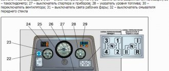
Gear shift diagram for tractor T-25
In today’s article we will look at what seems to be a question from the basics of driving a T-25 tractor, but it is quite often found on forums and among tractor drivers.
Let's also pay attention to some subtleties and repeat the basics of correct operation of the clutch. All these recommendations will help extend the life of the machine and avoid most of the ridiculous breakdowns.
How to change gears correctly on the T-25 tractor
Let us immediately note that the entire procedure is performed using levers and handles. Let's start right away with the principle of operation of the shift and consider in detail starting from the first releases of tractors. The levers themselves used for shifting gears are installed only on the first releases of T-25 tractors. They serve to select the required gear, change the traction of the car or its speed. The lever must be moved forward away from the driver or backward, then tilted to the left or right.
We have shown all possible positions of the levers in the diagram below.
If the lever is moved forward, it will turn on the USK (high) or LAM (low) stage of the tractor doubler. In order to put the tractor into reverse mode (RR), move the lever first to the rearmost position, then to the right.
Shifting gears, doublers or reverse must be done with the clutch completely disengaged.
There are few differences in the latest release models - all switching is performed using one lever.
T-25 tractor gear shift diagram
We provide you with a diagram for all existing modifications of the tractor, which is still relevant today.
The first diagram is the switching scheme itself on first-generation tractors, the second is the reverse and doubler. The last picture is the switching used in the latest modifications of the release.
agromania.com.ua
Gearbox design of the T-25 tractor
The T-25 gearbox is an example of a design solution that simplifies vehicle maintenance in the field.
When developing this unit, attention was paid to replacing individual parts without removing and disassembling the gearbox.
This is important when a breakdown occurs far from technical service centers or when workshops have a limited range of equipment for repairs.
Appearing in 1966, at the same time as the T-28 model, the T-25 tractor turned out to be more in demand and popular.
The reason for this popularity lies in the concept of the machine, and in particular the design of individual components.
PTO control levers
PTO speed shift lever on MTZ 80(82)
The lever for turning on the rear power take-off shaft 46 is located at the right wall of the cab. The lowered position of the lever corresponds to the disengaged PTO, and the raised position correspondingly turns on the rear PTO. The lever for switching operating modes of the rear PTO 55, or what is called the “cam clutch control lever,” is located at the base of the seat. Switching is carried out with the engine turned off by transverse movement of the lever relative to the axis of movement of the tractor. The middle position of the lever is neutral, the extreme right position corresponds to the independent operating mode, and the extreme left position corresponds to the synchronous operating mode. The rotation speed of the rear PTO is switched by lever 58 (in a separate figure), located on the lower wall of the housing of the intermediate part of the transmission in the cabin. One extreme position corresponds to a speed in independent mode of 540 rpm, the second extreme position is 1000 rpm. The selected position is fixed by tightening the control nut of the driver. In tractors equipped with a side PTO, the engagement lever is located on the cab field on the left side.
