5.3.1 Brake systems of ZIL vehicles
The car is equipped with three braking systems that allow you to reliably brake the car and trailer equipped with both single-line and two-line drives.
The service braking system allows you to control the movement of the vehicle and stop it reliably, quickly, regardless of the speed and load, or on an uphill or downhill slope. The brake drive is pneumatic, with separate braking of the front and rear wheels (Figure 5.24). The service brake system is controlled using a brake valve.
The parking brake system keeps the vehicle stationary on a level road or slope. The drive of the brake mechanisms of the parking brake system is mechanical, from brake chambers with spring energy accumulators installed on the rear axle. When the vehicle moves, the power springs of the energy accumulators are compressed by air pressure. When the air pressure in the cylinders of the energy accumulators drops, the springs activate the brake mechanisms of the rear wheels. The parking brake system is controlled by a manual brake valve located in the cab to the right of the driver's seat.
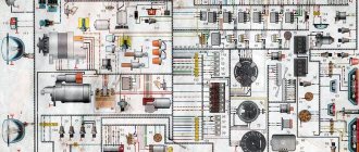
Figure 5.24 – Diagram of a pneumatic brake drive
1 – front brake chambers; 2, 15 – air cylinders of the service brake system; 3 – pneumoelectric Danish pressure reduction; 4 – condensate drain taps; 5 – air cylinder for moisture condensation; 6 – compressed air distributor; 7 – single safety valve; 8 – triple safety valve; 9 – pneumoelectric brake signal sensors; 10 – control outlet valves; 11 – valve of the service brake system; 12 – pressure regulator; 13 – anti-freeze fuse; 14 – rear brake chambers with spring energy accumulators; 16 – valve for parking and spare brake systems; 17 – pressure gauge; 18 – accelerator valve; 19 – two-line valve; 20 – brake force regulator; 21 – compressor
A spare or emergency brake system ensures that the vehicle stops in the event of a complete or partial failure of the service brake system. When the spare brake system is turned on, the air pressure compressing the power springs of the energy accumulators changes, and thus the intensity of braking is regulated. The spare brake system is controlled by the same brake valve as the parking brake system.
In the event of an emergency drop in pressure in the parking brake system, the power springs of the energy accumulators are activated and the vehicle is braked. In addition to the pneumatic system, there are screws for mechanical release of the brakes, built into the cylinders of the energy accumulators.
The condition of the brake systems is monitored using a light and sound alarm system, the sensors of which are installed at various points of the pneumatic brake drive, as well as control outlet valves.
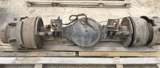
The mechanisms of the service brake system (Figure 5.25), a drum type with two internal pads, are installed on all wheels of the car. The brake mechanisms installed on the wheels of the rear axle are common to the service and parking brake systems.
The mechanisms are mounted on calipers, which are bolted to the flanges of the front axle steering axles, and connected to the rear axle housing flanges with rivets. Two brake pads with friction linings attached to them, made along a crescent profile in accordance with the nature of their wear, rest on eccentric axles fixed in the caliper. The axes of the shoes with eccentric supporting surfaces allow the shoes to be correctly aligned with the brake drum when assembling the brake mechanism. Brake drums are attached to the wheel hubs.
When braking, the pads 3 are moved apart by the expanding fist 8 and pressed against the inner surface of the drum 9. Rollers 7 are installed between the expanding fist and the pads. The pads are returned to the released state by tension springs 5.
The expansion knuckle shaft rotates in a bracket attached to the caliper with 1 bolts. At the splined end of the expanding fist shaft 8 there is an adjusting lever connected to the brake chamber rod by a fork and a pin. The shield, bolted to the rear axle caliper, protects the brake mechanism from dirt, and the oil deflector 10, attached to the inside of the brake drum, protects the brake mechanism from lubricant from the hub.
Figure 5.25 – Brake mechanisms of the service brake system
a – rear wheels; b – front wheels; 1 – caliper; 2 – block axis; 3 – brake pad; 4 – friction lining; 5 – tension spring; 6 – roller support; 7 – roller; 8 – expansion fist; 9 – brake drum; 10 – oil deflector
The adjusting lever is designed to reduce the gaps between the pads and the brake drum, which increase due to wear of the friction linings. The body of the adjusting lever contains a worm gear with a splined hole for installing an expansion knuckle and a worm with an axle on the shaft. The worm axis is fixed by a locking device consisting of a ball and a spring. The gear is held in place by caps attached to the housing. When turning, the worm turns the gear with the shaft and expansion fist, which pushes the shoes apart and presses them against the brake drum. When braking, the adjustment lever is turned by the brake chamber rod. The intensity of braking depends on the compressed air pressure and the stroke of the brake chamber rod.
Compressed air from the compressor (Figure 5.24) through the pressure regulator, condensate freeze guard and air cylinder flows to the double and triple safety valves, which, in turn, distribute the air, filling the air cylinders of the following independent brake circuits:
the first – the brake mechanisms of the front wheels;
the second – the brake mechanisms of the rear wheels;
the third – parking and spare brake systems, as well as a combined drive of the brakes of a trailer or semi-trailer.
All air cylinders have condensate drain valves, and pneumatic sensors for light indicators of compressed air pressure drop are built into these circuits.
A two-pointer pressure gauge is connected to the air cylinders of the brake drive of the service brake system.
To check the operation of the brake systems, control outlet valves are installed at various points of the pneumatic brake drive, to which portable pressure gauges are connected.
The first circuit includes the air tank, pressure drop sensor, lower section of the brake valve, front brake chambers and control valve.
Device
The cabin has 3 seats, 2 doors, panoramic glass, which provides excellent visibility. Large rear view mirrors are located on brackets. Door windows can be manually lowered and secured. The doors open at right angles, which is convenient for the driver and passengers. The cabin is equipped with large steps.
The height of the cabin is 2700 mm, it can be equipped with a berth. The steering has a mechanical and hydraulic drive. The hydraulic distributor and cylinder help improve steering control. Modern heating and ventilation systems have been installed.
The car is equipped with a 5-speed gearbox. The cardan system includes a chassis on which 2 shafts and intermediate supports are installed, which are connected by crosspieces. The load is transferred to the axles using the drive axle.
The supporting structure consists of a frame made of 2 metal channel beams. Longitudinal sections are fixed with cross members. Smooth movement is ensured by the design of the axle suspension. In the front and rear parts of the structure there are springs with shock absorption.
The rear springs are supplemented with metal sheets for strength. The truck is compatible with a large number of additional add-ons. The most commonly used emergency repair equipment includes a diesel generator mechanism with a repair shop and a fuel supply. The universal chassis allows tool boxes to be placed underneath. The machines are used to perform repair work at remote sites.
Ambulance vehicles, fuel tankers and garbage trucks, hydraulic lifts, tankers, loaders, dump trucks, bunker vehicles and other equipment are represented by this truck. The car can be used on any type of road.
The machine is characterized by increased maneuverability, maneuverability, operational reliability and ease of maintenance.
- power supply with standard connectors;
- versatility of the coupling device;
- connecting trailer brakes to vehicle systems.
The machine can transport bread, food, industrial products, frozen foods (refrigerated trucks). Hydraulic lifts can be used in the construction and installation of structures.
Brake system
The vehicle's braking system consists of 3 circuits and includes: a service brake with pneumatic control and a 2-circuit hydraulic system along the axles on the front and rear wheels. The axles have drum shoes with the possibility of installing anti-locking. There is a parking and spare brake with a drive circuit, pneumatic transmission, and drum shoes. If the cargo chassis is used as part of a road train, then the circuit is equipped with a crane to control the trailer brake.
Electrical equipment
The vehicle's electrical system is single-wire, with a voltage of 12 V. The ignition has a contact-transistor design. Starter voltage is 12 V, remote control and electromagnetic load relay are installed.
There is a 12 V battery, brand 6-ST-81, with a capacity of 81 A/h. The G-130 series alternating current generator creates a direct current of 28 A and a power of 350 W. The same voltage is maintained at different speeds using an electromechanical relay and an electronic control circuit.
The electrical equipment can be equipped with additional options: a pre-heater to make starting the engine easier in cold weather. A bed heating system can be installed. An upgraded ignition circuit with microprocessors is installed. The electrical circuit makes it possible to install an insulation cover and a recoil bar.
Device and characteristics
The design of the truck is based on a shortened frame. The front beam is mounted on springs, which are complemented by 2-way hydraulic shock absorbers. The rear axle has a standard suspension for ZIL products, which includes main and additional springs.
The following power units were used:
- 185-horsepower diesel ZIL-645, having a cylinder volume of 8.74 liters;
- boosted to 200 hp version of the ZIL-6454 diesel engine, cylinder capacity 9.56 l;
- petrol V-shaped engine with a power of 150 hp;
- experimental diesel ZIL-0550, which had a cylinder volume of 6.28 liters and developed 132 hp.
The performance characteristics of the vehicles differ depending on the engine type, but the load capacity remains the same (6830 kg for the chassis and 6000 kg for the onboard version). The most widespread cars are those with gasoline engines, which were produced before 2005-07. The trucks were equipped with a 170-liter fuel tank and consumed about 26 liters of gasoline per 100 km (at a speed of 60 km/h).
A single-disc dry friction clutch is used to transmit torque. The gearbox is 5-speed, equipped with 2 synchronizers for 2-3 and 4-5 speeds. Switching is carried out by a lever mounted on the cover of the unit. The rear axle is equipped with a 1-stage bevel gearbox with a hypoid tooth profile. There are versions with an old bridge design, which is equipped with a 2-speed gearbox.
The gearbox has space for installing a power take-off gearbox. The unit is designed to connect gear oil pumps of an additional hydraulic system. Fluid supplied under pressure is used to drive additional equipment. For example, such a pump is used on automobile towers PART 28 or PSS 131-22, built on the basis of the ZIL-43336 1 chassis.
Between the output shaft of the gearbox and the shank of the main pair there is a cardan shaft equipped with hinges on needle bearings. The shaft, made of thin-walled pipe, consists of 2 sections. To reduce vibrations, an additional support support is used.
Machine Specifications:
- length (chassis) - 6620 mm;
- wheelbase - 3800 mm;
- width (along the cabin wings) - 2380 mm;
- front overhang - 1153 mm;
- height - 2580 mm;
- ground clearance (to the axle housing) - 220 mm;
- permissible vehicle weight - 11000 kg.
- design speed - 90 km/h.
The brake system is pneumatically driven and equipped with drum wheel mechanisms. The system includes several receivers with a capacity of 20 liters each. The design of the units includes drain valves designed to remove condensate.
The family of machines included the following modifications:
- chassis with a 2-row cabin, designed for installation of fire-fighting equipment;
- flatbed truck;
- export version for temperate climates; a tropical version of the truck was also produced separately;
- chassis for installing specialized add-ons.
All versions used an all-metal cabin, equipped with a separate seat for the driver and a sofa for 2 passengers.
Specifications
ZIL-433362 has the following technical characteristics:
- Wheel formula - 4x2.
- Dimensions: length 6.6 m, width 2.4 m, height 2.6 m.
- Maximum cargo weight is 6830 kg.
- Vehicle weight - 3945 kg.
- The permissible chassis weight is 11200 kg.
- The maximum weight of the road train is 19200 kg.
- Permissible load on the road surface from the curb weight through the tires: front wheels - 21750 N, rear axle - 17700 N.
- The greatest load on the road surface from the total weight of the vehicle through the tire of the front wheels is 30,000 N, the rear axle is 82,000 N.
- The turning radius is 6.9 m.
- The highest speed with the full weight of the truck is 90 km/h, with the full weight of the road train - 80 km/h.
- Fuel tank volume - 170 l.
Engine
The car is equipped with a ZIL-508 carburetor engine. This is an 8-cylinder engine with a capacity of 6 liters. Motor power 150 hp, or 110 kW. Engine speed is 3200 per minute. The torque is 41 kgf/m. The motor design is equipped with valves located at the top. A total of 16 valves are installed. Engine weight with additional equipment is 640 kg.
Device and technical parameters
The cars use a straight-sided body. The ZIL-450650 and 450850 machines differ in the number of unloading directions - in 3 and 1 direction, respectively. The lower parts of the sides of the body are beveled, which reduces the likelihood of cargo sticking. The body is welded from stamped elements, equipped with a movable tailgate, which is hinged at the bottom or top. When unloading, the side opens automatically; forced unlocking is possible. Installation of extension sides is provided (on the agricultural version 45065).
The drive of the body control mechanisms on the ZIL-MMZ-45085 is hydraulic. To tip the body, a plunger telescopic cylinder assembled from 4 sections is used. When supplying working fluid, the unit provides force in 1 direction. The body lowers under its own weight. The parts of the dump truck are mounted on a steel subframe.
To supply fluid under pressure, a gear pump station located on the power take-off is used. The unit is a 1-stage gearbox mounted on the chassis gearbox. The design provides an increase in rotation speed by 1.2 times. During power take-off, the gears are connected to the reverse intermediate carriage.
The gearbox control is located in the driver's cabin. To turn on the selection, a remote electro-pneumatic drive is used. Compressed air comes from the truck's brake system reservoirs. The distribution of fluid flows is carried out by a spool block consisting of 2 sections. To store the working fluid, a 21-liter steel tank made of 2 stamped halves is used. The neck has a rod oil level meter and a strainer.
Technical characteristics of the dump truck when using the ZIL-494500 chassis:
- fuel consumption per 100 cycles of raising and lowering the body - no more than 5 liters;
- maximum speed when fully loaded - 90 km/h;
- fuel supply (tank on the side of the frame) - 170 l;
- fuel consumption (control at 80 km/h) - 26 liters per 100 km.
The driver is located in a closed metal cabin that allows the carriage of 2 passengers. Standard equipment includes a liquid heater and a windshield cleaning system. The individual driver's seat is adjustable.
Engine
The ZIL-MMZ-45065, built on the model 494560 chassis, uses a V-shaped gasoline engine. The unit develops 150 hp. at 3200 rpm. The cars were equipped with a catalytic converter for exhaust gases without feedback.
There are dump trucks equipped with a 100-horsepower D-245 tractor diesel engine with a turbocharger. The parameters of the power unit made it possible to maintain the load capacity, but the dynamic characteristics of the truck were reduced.
Transmission
A dry 1-disc clutch is installed on the engine flywheel. The shutdown drive is equipped with a pneumohydraulic amplifier. ZIL-MMZ-45085 vehicles use a manual 5-speed gearbox that does not have a synchronizer at 1st forward speed. There is no overdrive, the 5th gear ratio is 1.00.
The speed selection is carried out by a rocker lever mounted on the box lid. On the side surface of the crankcase there is a hatch for the power take-off gearbox. The design allows the selection of 30 hp, while the machine must be stationary.
The trucks use a rear axle with a 1-stage torque transmission. The main pair consists of 2 gears with a hypoid tooth profile. Between the box and the bridge there are 2 cardan shafts with hinges on needle bearings. The design of the unit provides for a movable connection and additional support.
Wheels and tires
The truck is equipped with 7.0*20 disc wheels with radial tube tires 260R508 or 9.00R20. The rear axle is equipped with dual wheels; footings are used for fastening. The spare wheel is located under the folding cargo platform, mounted on a special support.
Electrical equipment
The voltage sources are a battery and an alternator with a semiconductor rectifier. A 1-wire wiring diagram is used, the negative pole of sources and consumers is connected to the vehicle body.
On a gasoline ZIL-MMZ-45065, the on-board voltage is 12V. Diesel engines require an increase in the power of the electric starter, so on such machines the voltage in the starting circuit is raised to 24V.
Dimensions and weight characteristics
Dump truck parameters:
- length (when driving on roads) - 6370-6455 mm;
- width (along the sides of the platform) - 2420-2500 mm;
- height (to the edge of the front side) - 2810 mm;
- height (with additional sides) - 3290 mm;
- height with raised platform - 3850 mm;
- body lift angle - 50°;
- load capacity - 5500 kg;
- vehicle weight (with fuel, but without people in the cabin) - 6090 kg;
- permitted gross weight - 11815 kg;
- trailer weight - up to 9000 kg (with reduced dynamic parameters);
- turning radius (without trailer) - 6.9 m.
Modifications
Thanks to the universal design of the chassis, there are a large number of add-ons, which made it possible to create many modifications of the ZIL-433362 vehicle.
The ZIL-433362 aerial platform is a hydraulic lift equipped with a boom, used for lifting loads. The AKMP-3 model is used to clean roads in cities and airports. In summer, this unit cleans the roadway from dirt and dust, and in winter – from snow. The technical characteristics of the garbage truck allow the installation of an additional kit for cleaning the pipe surface. The device can be used to extinguish a fire.
The ERMZ asphalt distributor is designed for transporting bitumen and applying it to the surface of the roadway during road repairs. Used for transporting fuel oil, peat and lubricants.
ATs-3.5-40 is a tanker truck that is used as a fuel truck or when extinguishing a fire. Fire tankers can deliver approximately 2 tons of foaming water.
ZIL-433362 KO - garbage truck for unloading garbage from containers. When working, use a push plate with the body folded down. A manipulator is installed on the side. The machine has high maneuverability.
The municipal watering machine 713 01 520 KO on the ZIL-433362 chassis is used for watering plants in parks, squares and streets. KO-520 is also used for washing road surfaces.
Reviews and prices
A new truck costs 1.2-2 million rubles. Used cars cost 0.8-1.5 million rubles. Cars that have been in operation for more than 12 years cost 250 thousand rubles.
Our organization uses a fire tanker based on a ZIL truck chassis. This equipment is characterized by high strength, reliability and good cross-country ability. The unit was used many times during fires and showed high technical data.
I work on a ZIL refrigerated truck. The machine transports chilled products. We serve retail stores, meat processing plants and other organizations. The truck is maneuverable, has excellent speed and load capacity.
Brake system ZIL-130
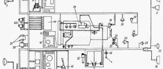
The brake system of ZIL 130-431410 vehicles can be multi-wire or single-circuit, depending on the time of production of the vehicle. Brake system diagrams are shown in Figures 12-15 and 12-16. The multi-circuit brake drive of ZIL-431410 vehicles differs from ZIL-433360 vehicles in the number of devices used and their connection. The brake drive devices themselves are the same. By car
multi-circuit braking system
Diagram of a service brake system with a single-circuit undivided drive
single-circuit braking system
Braking systems, as we see in the pictures, come in 2 types. We will make a multi-circuit system similar to a single-circuit one. Let's remove unnecessary taps, which we can say are not needed for the operation of the brake system. Let's look at the third picture. Here I want to show how I made a single-circuit system from a multi-circuit ZIL-431410 system.
I removed valves such as: a brake force regulator, a trailer brake system control valve with a two-wire drive, a single safety valve, pneumatic-electric pressure reduction sensors, connecting heads for trailer brake drives. As they say, the simpler, the more reliable. The fewer air pressure tubes, the less air will bleed.
rebuilt brake system
In the upper and lower pictures, look at how the diagram of the pneumatic brake drive is made and you will see the difference. Using this diagram, you will make all the connections, I think you will figure it out, there is nothing complicated.
5.3.1 Brake systems of ZIL vehicles
5.3.1 Brake systems of ZIL vehicles
The car is equipped with three braking systems that allow you to reliably brake the car and trailer equipped with both single-line and two-line drives.
The service braking system allows you to control the movement of the vehicle and stop it reliably, quickly, regardless of the speed and load, or on an uphill or downhill slope. The brake drive is pneumatic, with separate braking of the front and rear wheels (Figure 5.24). The service brake system is controlled using a brake valve.
The parking brake system keeps the vehicle stationary on a level road or slope. The drive of the brake mechanisms of the parking brake system is mechanical, from brake chambers with spring energy accumulators installed on the rear axle. When the vehicle moves, the power springs of the energy accumulators are compressed by air pressure. When the air pressure in the cylinders of the energy accumulators drops, the springs activate the brake mechanisms of the rear wheels. The parking brake system is controlled by a manual brake valve located in the cab to the right of the driver's seat.
Figure 5.24 – Diagram of a pneumatic brake drive
1 – front brake chambers; 2, 15 – air cylinders of the service brake system; 3 – pneumoelectric Danish pressure reduction; 4 – condensate drain taps; 5 – air cylinder for moisture condensation; 6 – compressed air distributor; 7 – single safety valve; 8 – triple safety valve; 9 – pneumoelectric brake signal sensors; 10 – control outlet valves; 11 – valve of the service brake system; 12 – pressure regulator; 13 – anti-freeze fuse; 14 – rear brake chambers with spring energy accumulators; 16 – valve for parking and spare brake systems; 17 – pressure gauge; 18 – accelerator valve; 19 – two-line valve; 20 – brake force regulator; 21 – compressor
A spare or emergency brake system ensures that the vehicle stops in the event of a complete or partial failure of the service brake system. When the spare brake system is turned on, the air pressure compressing the power springs of the energy accumulators changes, and thus the intensity of braking is regulated. The spare brake system is controlled by the same brake valve as the parking brake system.
In the event of an emergency drop in pressure in the parking brake system, the power springs of the energy accumulators are activated and the vehicle is braked. In addition to the pneumatic system, there are screws for mechanical release of the brakes, built into the cylinders of the energy accumulators.
The condition of the brake systems is monitored using a light and sound alarm system, the sensors of which are installed at various points of the pneumatic brake drive, as well as control outlet valves.
The mechanisms of the service brake system (Figure 5.25), a drum type with two internal pads, are installed on all wheels of the car. The brake mechanisms installed on the wheels of the rear axle are common to the service and parking brake systems.
The mechanisms are mounted on calipers, which are bolted to the flanges of the front axle steering axles, and connected to the rear axle housing flanges with rivets. Two brake pads with friction linings attached to them, made along a crescent profile in accordance with the nature of their wear, rest on eccentric axles fixed in the caliper. The axes of the shoes with eccentric supporting surfaces allow the shoes to be correctly aligned with the brake drum when assembling the brake mechanism. Brake drums are attached to the wheel hubs.
When braking, the pads 3 are moved apart by the expanding fist 8 and pressed against the inner surface of the drum 9. Rollers 7 are installed between the expanding fist and the pads. The pads are returned to the released state by tension springs 5.
The expansion knuckle shaft rotates in a bracket attached to the caliper with 1 bolts. At the splined end of the expanding fist shaft 8 there is an adjusting lever connected to the brake chamber rod by a fork and a pin. The shield, bolted to the rear axle caliper, protects the brake mechanism from dirt, and the oil deflector 10, attached to the inside of the brake drum, protects the brake mechanism from lubricant from the hub.
Figure 5.25 – Brake mechanisms of the service brake system
a – rear wheels; b – front wheels; 1 – caliper; 2 – block axis; 3 – brake pad; 4 – friction lining; 5 – tension spring; 6 – roller support; 7 – roller; 8 – expansion fist; 9 – brake drum; 10 – oil deflector
The adjusting lever is designed to reduce the gaps between the pads and the brake drum, which increase due to wear of the friction linings. The body of the adjusting lever contains a worm gear with a splined hole for installing an expansion knuckle and a worm with an axle on the shaft. The worm axis is fixed by a locking device consisting of a ball and a spring. The gear is held in place by caps attached to the housing. When turning, the worm turns the gear with the shaft and expansion fist, which pushes the shoes apart and presses them against the brake drum. When braking, the adjustment lever is turned by the brake chamber rod. The intensity of braking depends on the compressed air pressure and the stroke of the brake chamber rod.
Compressed air from the compressor (Figure 5.24) through the pressure regulator, condensate freeze guard and air cylinder flows to the double and triple safety valves, which, in turn, distribute the air, filling the air cylinders of the following independent brake circuits:
the first – the brake mechanisms of the front wheels;
the second – the brake mechanisms of the rear wheels;
the third – parking and spare brake systems, as well as a combined drive of the brakes of a trailer or semi-trailer.
All air cylinders have condensate drain valves, and pneumatic sensors for light indicators of compressed air pressure drop are built into these circuits.
A two-pointer pressure gauge is connected to the air cylinders of the brake drive of the service brake system.
To check the operation of the brake systems, control outlet valves are installed at various points of the pneumatic brake drive, to which portable pressure gauges are connected.
The first circuit includes the air tank, pressure drop sensor, lower section of the brake valve, front brake chambers and control valve.
The second circuit includes an air tank, a pressure drop sensor, an upper section of the brake valve, a brake force regulator with an elastic element, rear brake chambers with spring energy accumulators and a control outlet valve.
The third circuit includes an air cylinder, a pressure drop sensor in the circuit, a brake valve for the parking brake system, an indicator sensor for the activation of the parking or spare brake systems, an accelerator valve, a two-line valve that prevents the activation of spring energy accumulators when the service and parking brake systems are simultaneously engaged, a control output valve , spring energy accumulators, as well as a single safety valve, trailer brake control valves with two-line and single-line actuators, two connection heads for two-line actuators and one connection head type A for single-line actuators of the trailer brake system.
When the vehicle is moving, the air cylinders of the pneumatic drive are filled with compressed air. From the air cylinders, compressed air is supplied to the sections of the brake valve of the service brake system, the brake valve of the parking brake system, the accelerator valve, and the single safety valve. From the accelerator valve, through a two-line bypass valve, compressed air is supplied to spring energy accumulators, the springs of which are in a compressed state under the influence of air. From the single safety valve, compressed air is supplied to the trailer brake control valves with a single-line and two-line drive, the connecting head feeding the lines of the two-line drive, and from the trailer brake control valve with a single-line drive to the connection head of type A.
When driving a tractor-trailer with a single-line brake drive, the coupling head type A of the tractor is connected to the coupling head type B of the trailer, and compressed air enters the trailer brake system through a single safety valve and a control valve for the single-line trailer brake system. The connecting heads of the two-wire drive of the trailer brake system must be closed with covers.
When a tractor-trailer with a two-wire brake drive is moving, the connecting heads that supply and control the trailer brake system are connected to the corresponding trailer heads and compressed air enters the trailer brake system through the supply line through a single safety valve. The pressure in the control line is equal to atmospheric pressure.
When you press the pedal of the service brake system, compressed air supplied from air cylinders to the sections of the brake valve enters through the outlet of the upper section and the brake force regulator into the brake chambers, which operate the brake mechanisms of the rear wheels. From the lower section of the brake valve, compressed air enters the brake chambers of the front wheels. Thus, the car's wheels are braked at an intensity selected by the driver, based on driving conditions. At the same time, compressed air from both sections of the brake valve is supplied to the control cavities of the trailer brake system control valve with a two-wire drive.
When a vehicle with a trailer equipped with a single-line brake actuator brakes, the two-line trailer brake control valve is activated and supplies compressed air to the line to the single-line trailer brake control valve. As a result, the connecting lines of the tractor and trailer are connected to the atmospheric outlet of the valve.
The trailer brake air distributor passes compressed air from the trailer's cylinders to the brake chambers, which operate the brakes on the trailer's wheels.
When braking a vehicle with a trailer equipped with a two-line brake actuator, the two-line trailer brake control valve supplies compressed air to the control line of the two-line actuator. As a result, the air distributor is activated and allows air from the trailer's cylinders into its brake chambers.
When the pedal of the service brake system is released, both sections of the brake valve are connected to the atmospheric outlet. Compressed air from the front brake chambers exits through the atmospheric outlet of the two-section brake valve, and from the rear brake chambers through the atmospheric outlet of the brake force regulator, as a result of which the front and rear wheels are released. At the same time, the air pressure in the lines leading to the control valve of the trailer brake system with a two-wire drive drops. The control line of the two-wire drive is connected to the atmospheric outlet of the valve, which leads to the release of the trailer wheels.
Due to a drop in pressure in the control cavity of the trailer brake control valve with a single-line drive, the latter is activated and passes compressed air into the connecting line of the single-line drive. The air from the trailer's brake chambers exits through the air distributor into the atmosphere, and the trailer wheels are released.
Thus, when braking, the service brake system operates the first and second circuits of the brake drive of the front and rear wheels, as well as part of the third circuit, a combined trailer brake drive controlled from the first and second circuits.
If one of the circuits fails, the others remain operational. If the primary circuit is damaged and there is no compressed air in the cylinder, braking is carried out by the brake mechanisms of the rear wheels of the car and trailer. If the secondary circuit is damaged and there is no compressed air in the cylinder, braking is carried out by the brake mechanisms of the front wheels of the car and trailer.
To brake a car or road train while parked, the parking brake system valve handle must be set to the rear fixed position. In this case, the control cavity of the accelerator valve will be connected to the atmospheric outlet of the manually controlled brake valve, and air will be released from the energy accumulator cylinders through the atmospheric outlet of the accelerator valve. The springs, expanding, will activate the brake mechanisms of the rear wheels. At the same time, the two-wire trailer brake control valve will turn on, supplying compressed air to the two-wire control line and the single-line trailer brake control valve. The latter will release air from the connecting line of the single-wire drive. Thus, the trailer braking system is activated in the same way as when braking with the pedal of the service brake system. To disengage the parking brake system, the parking brake valve handle should be set to the forward position. In this case, air from the air cylinder will flow through the tap into the control cavity of the accelerator valve. The valve, when activated, will pass compressed air from the air cylinder through the two-line bypass valve into the cylinders of the spring energy accumulators and the power springs will compress.
The brake valve has a tracking device that allows you to brake the car with varying intensity depending on the position of the handle. When the tap handle is turned to a particular angle, compressed air is released from the control cavity of the accelerator valve, and the pressure in the cavity decreases in proportion to the angle of rotation of the tap handle. In this case, through the atmospheric outlet of the accelerator valve, air is released from the cylinders of the spring accumulators in an amount proportional to the decrease in air pressure, and the trailer or semi-trailer is slowed down with an intensity also proportional to the decrease in air pressure in the cylinders of the spring energy accumulators.
In the event of an emergency drop in pressure in the circuit, spring energy accumulators are activated and the car slows down. To release the car in this case, you need to turn out the mechanical release screws built into the cylinders of the spring energy accumulators (Figure 5.26) all the way.
Figure 5.26 – Device for mechanical release of the parking brake system
1 – spring energy accumulator; 2 – screw; 3 – socket wrench
The screw, rotating in the threaded boss of the cylinder, moves up and through the thrust bearing, acting on the piston, lifting it together with the pusher to the uppermost position. The power spring is compressed and the brake chamber rod returns to its original position.
The braking signal when the brake systems are operating is activated from a pneumoelectric sensor installed in the line after the control valve for the two-wire trailer brake system.