Crane KDE 163 technical characteristics
§ 34. ELECTRICAL DIAGRAMS OF RAILWAY CRANES
Circuit diagram of diesel-electric railway cranes KDE-163 and KDE-253
In Fig. Figure 64 shows a schematic electrical diagram of the diesel-electric cranes KDE-163 and KDE-253, which is the most complete for the KDE series cranes. Using this diagram, we will follow the implementation of the main operations of the cranes. Conventional graphic symbols for the electrical circuit are given in table. 16a.
Once the diesel engine is started and its stability and operating mode are established, the G1 generator will begin to generate three-phase alternating current and a normal voltage of 380-400 V will be established at its terminals.
By manually turning on the three-pole linear switch B7 to the power position from the generator, current is supplied to the power and auxiliary (control, lighting, alarm) lines. In this case, all auxiliary lines and power lines of the cargo electromagnet are turned on directly through the switch, while all others (power lines) are additionally turned on through the linear contactor P12. This was done in order to ensure the possibility of controlling the crane and safe operation of the load magnet, since even if the linear contactor is turned off and the power lines are de-energized, the load electromagnet remains energized and will not release the taken load. Turn on the linear contactor with the Kn9 start button; At the same time, for safety reasons, the so-called zero blocking is implemented, which allows the linear contactor to be turned on and current supplied to the power lines only if all controllers and command controllers are in zero positions, i.e. in the non-working position, and the door to the machine room compartment is securely closed.
By pressing the Kn9 button, the coil of the linear contactor will be energized through the following circuit: fuse Prb - wire 02 - coil P12 - opening contacts of mechanical interlocks MB1 and MB2 - closing contact of the door closing block B23 - emergency switch B22 - zero contacts of the motion controller B1 and the rotation controller B2 - zero contacts of command controllers VZ and B4 - start button Kn9 - wire 01 - fuse Prb.
When the linear contactor is turned on, its block contacts close the power circuit of the P12 coil, bypassing the zero contacts of the controller and command controllers, thereby ensuring the ability to transfer them to operating positions, i.e., the ability to turn on the mechanisms.
When any of the four maximum current relays RZ, P4, P5, P6 is triggered, the mechanical interlock MB1 is triggered, and when relays P7, P9 and P10 are triggered, the MB2 lock is triggered, breaking the power circuit of the contactor coil P12, turning it off and de-energizing the power line.
windings of the electric motor M10 and its rotor will begin to rotate, ensuring the lifting of the load.
A start-up resistor R4 is included in the circuit of the rotor winding of the electric motor, and in the first position of the command controller it is fully turned on, so the rotational speed of the electric motor will be the lowest. With the transfer of the command controller to the second position, its contacts are additionally closed and coil P19 receives power through the following circuit: fuse Prb - wire 02 - closing block contact P12 - coil P19 - closing contact VZ - closing block contact P12 - wire 01 - fuse Prb. Contactor P19 is activated and with its power contacts closes part of the ballast resistor, as a result the electric motor M10 will receive an increased rotation speed. When the command controller is moved to the third position, contactor P20 will operate in a similar way, removing the entire ballast resistor from the rotor circuit, resulting in the highest lifting speed.
The M9 brake electric motor is connected directly to the terminals of the main electric motor, so it turns on and off simultaneously with it, releasing the brake when the main engine is turned on and braking when it stops.
The load is lowered by moving the VZ command controller to the descent position due to the fact that the lowest descent speed corresponds to the third position, i.e. the ballast resistor R4 is completely removed from the rotor winding circuit, turning on the electric motor for descent must begin from the third position, quickly moving the command controller to it . When the command controller is installed in the third descent position, contactor P21 will also be turned on, the coil of which will receive power through the circuit: fuse Prb - wire 02 - closing block contactor P12 - coil P21 - NC block contact of the contactor P22 - contact of the command controller VZ - NC contact of the minimum switch number of rope turns on the drum B32 - opening contact of the rope loosening switch B31 (during grab operation) or closing contact of the VZO switch (during load operation) - closing block contact P12 - wire 01 - fuse Prb and contactor P20, closing and outputting ballast resistor R4 from the rotor winding circuit.
The descent is stopped by quickly moving the command controller to the zero position.
The M12 electric motor is turned on and controlled by the command controller somewhat differently from the control of the M10 electric motor. There are two modes of operation for lowering the load: normal descent and descent in dynamic braking mode in order to obtain low creeping descent speeds. Turning on the electric motor in normal mode is completely similar to turning on the M10 electric motor, with the only difference being that the MP brake electric motor is not connected directly to the terminals of the main motor, but independently through a magnetic starter P26, in the coil circuit of which the brake release pedal switch B35 is connected, which allows you to release the brake when the brake is not applied. Mil electric motor, which is important when operating the crane with a grab.
Basic technical data of jib cranes
By the nature of work on railway transport, rail-mounted cranes are the most common, although crawler-mounted and pneumatic cranes are also used. Cranes consist of two main parts: a running platform and a lifting and slewing frame with a boom and load-handling devices. The rotating frame also houses the power unit, the main operating mechanisms of the crane, a boom with load-handling devices and controls.
Each self-propelled full-rotating jib crane has at least four mechanisms: lifting the load, changing the boom reach, rotating the top of the crane, and a mechanism for moving the crane self-propelled. All ethn mechanisms can be driven from individual drives or in combination from one power drive.
In Fig. 1, 2 show full-rotating jib cranes, rail-mounted cranes with a lifting capacity of 15, 16 tons.
The technical characteristics of the crane are the lifting capacity, the power of the power drive and the total power of the installed engines, the speed of lifting the load and moving the crane self-propelled, the time of complete change of the boom radius, the rotational speed of the rotating frame of the crane, the maximum lifting height of the load-handling device, the radius described by the rotating part of the crane, overall dimensions , weight of the crane and permissible speed of transportation of the crane as part of the train.
The power of thermal engines (steam, internal combustion engines) is expressed in horsepower (hp), and electric in kilowatts (kW).
The speed of lifting cargo and self-propelled movement is expressed in meters per 1 minute (m/min), and the speed of transporting a crane as part of a train is expressed in kilometers per 1 hour (km/h).
The time it takes to raise or lower the crane boom from one extreme position to the other is expressed in minutes (min).
The speed of rotation of the crane's upper frame is characterized by the rotation speed.
The boom reach is the horizontal distance between the axis of rotation of the crane and the vertical line passing through the load suspension point.
The size of the area served by the crane depends on the reach of the boom: the greater the reach, the larger this area; but as the reach increases, the possibility of the crane overturning increases, as its stability decreases; therefore, as the reach increases, the weight of the load being lifted must be reduced. For increased stability and the ability to lift heavier loads
Rice. 1. Diesel-electric crane KDE-161 with a lifting capacity of 16 tons:
1 — crane portal; 2-crane body; 3 - cargo boom; 4 — rotating part of the crane; 5 — rotating support; 6 — diesel generator set; 7 — muffler; 8 — boom lifting mechanism; 9 — cable holder; 10 — control station; 11 — running trolley; 13 — lower running frame; 13 — cargo winch; 14 — outrigger; 15 — movement mechanism; 16 — fuel tank; 17 — rotation mechanism; 18 — driver’s seat; 19 — control panel
/ — cargo drum shaft; 2 - main shaft; 3 — vertical drive shaft of wheelsets; 4- horizontal shaft of the boom lifting mechanism; 5 — horizontal rotation shaft; 6 — vertical shaft of the boom lifting mechanism; 7 - main valve; 8 - steam regulator; 9 — boom drum axis; 10 — boom lift drum; //- vnlka; 12 — traverse; 13 — cargo drums; 14 - load capacity indicator; 15-upper support ring; 16 — support rollers; 17- lower support ring; 18-nut of the central kingpin; 19 — central kingpin; 20 — vertical rotation shaft; 21 — horizontal wheel pair drive shaft; 22 — cam clutch; 23 — manual drive of the trolley brake; 24 — rotation clutches; 25 — rotation brake; 26 — load clutches; 27 — load brakes; 28 — wheel pair drive clutches; 29 — wheel drive brake; 30 — trolley air brake drive; 31 — outrigger; I - worm; And — gear of the boom lifting mechanism; III - crown of rotation; IV - cylindrical gear of the vertical rotation shaft; V - cylindrical gear of the horizontal wheel pair drive shaft; VI - lower bevel gear of the vertical wheel pair drive shaft; VII - bevel gear of the horizontal wheel pair drive shaft; VIII - split spur gear; IX — cylindrical gear of the cargo drum shaft; X - spur gear of the main shaft; XI - intermediate gear; XII - left cylindrical gear of the horizontal shaft of the boom lifting mechanism; XIII - bevel gear of the horizontal shaft of the boom lifting mechanism; XIV - bevel gear of the horizontal rotation shaft; XV - bevel gear of the horizontal rotation shaft; XVII — right cylindrical gear of the horizontal shaft of the boom lifting mechanism; XVIII—
Other company announcements
3
Kedr, LLC, RU, 3267 km
Diesel locomotive TEM 2UM 1991, traction ED-118, Bandages 60 mm, flange 28-29 mm. Safety devices available. Requires repairs to the extent of TR-3
4
Kedr, LLC, RU, 3267 km
Diesel locomotive TGM 4A manufactured in 1985. Completed TR-2 in 2022. The diesel locomotive has been tested and is ready for work. Warranty – 1 year. Wheel rim thickness – 68mm….
2
Kedr, LLC, RU, 3267 km
I will sell the TGM 4 shunting locomotive, produced in 1987., workingLocation: Budenovsk, Stavropol TerritoryComplete, serviceable, with…
- Added91
- Loaded
YouTube6:46
Real Train Guide: How to get a driver to drive a train? Metant | Real Train Mod Russian | IR
171 viewsthree months ago
YouTube3:47
How to make a railway crossing in Real Train Mod? | RTM Crossing Tutorial Metant | Real Train Mod Russian | IR
three months ago
YouTube4:34
Trolleybus in Minecraft. Pre-alpha version. RealTrainMod. Trolleybus in Minecraft. Metant | Real Train Mod Russian | IR
194 views7 months ago
YouTube23:59
Tutorial on building a contact network in RealTrainMod Metant | Real Train Mod Russian | IR
8 months ago
YouTube23:17
MVP RTM 1.5 Metant Tutorial | Real Train Mod Russian | IR
8 months ago
YouTube15:00
Automation of train routes using NBT tags | RealTrainMod [1.12.2/1.7.10] minecraft Metant | Real Train Mod Russian | IR
9 months ago
YouTube43:00
New Year's trip to EP1 in Minecraft! Metant | Real Train Mod Russian | IR
9 months ago
YouTube1:33:35
RTM server ExtraDirt.ru (stream No. 4) Metant | Real Train Mod Russian | IR
9 months ago
YouTube14:21
Guide to the mod /REAL TRAIN MOD/ #2 ARROWS //REAL TRAIN MOD OVERVIEW #1 ARROWS// RTM Metant | Real Train Mod Russian | IR
11 months ago
YouTube15:22
Guide to the mod /REAL TRAIN MOD/ #1 INSTALLATION //REAL TRAIN MOD OVERVIEW #1 INSTALLATION// RTM Metant | Real Train Mod Russian | IR
383 views11 months ago
YouTube22:07
Tutorial on the mechanisms of the RealTrain Metant mod | Real Train Mod Russian | IR
202 views1 year ago
YouTube3:05
Minecraft: Stations mod. Departure mark Metant | Real Train Mod Russian | IR
a year ago
YouTube22:21
RTM: CARD FROM SUBSCRIBER #2. EXTINCENT METRO? Metant | Real Train Mod Russian | IR
a year ago
YouTube7:42
RTM: ?REAL JR. ?REAL YAZH. HIGH-SPEED TRAIN. SPEED TRAIN. Metant | Real Train Mod Russian | IR
a year ago
YouTube52:13
Automatic alarm without redstone on the RealTrain mod! Metant | Real Train Mod Russian | IR
451 viewstwo years ago
YouTube12:24
MCTE: WORLD EDIT Nonsense? HOW TO USE MCTE? Metant | Real Train Mod Russian | IR
two years ago
YouTube7:44
RTM: TAKEN AWAY ON KTM-5. KRASNOKAMSKY TRAM!? KRASNOKAMENSK TRAM Metant | Real Train Mod Russian | IR
571 viewstwo years ago
YouTube4:28
RTM?! MatoiVanillaPack Metant | Real Train Mod Russian | IR
two years ago
YouTube5:27
RTM: TRACK TILTING. TOWING THE WAYS Metant | Real Train Mod Russian | IR
two years ago
YouTube12:19
RTM: ? TECHNICIAN IN RTM!? MACHINIST IN RTM?! Metant | Real Train Mod Russian | IR
two years ago
YouTube5:17
RTM: KDE-253 DESTROYER CRANE! CRANE KDE-253 THE DESTRUCTIVE! MATOIVANILLAPACK Metant | Real Train Mod Russian | IR
two years ago
YouTube4:05
RTM: DRILLING MACHINE. DRILLING MACHINE Metant | Real Train Mod Russian | IR
two years ago
YouTube16:18
Minecraft: RTM Russian trains. RTM Russian trains. DarkKrond pack. Metant | Real Train Mod Russian | IR
two years ago
YouTube1:14
Minecraft: WIPERS ON TRAIN IN RTM?! THE BEST TRAIN IN THE REAL TRAIN MOD. RTM E231 Metant | Real Train Mod Russian | IR
173 viewstwo years ago
YouTube6:40
RTM: MCTE? Peregrine Falcon KILLED A RESIDENT! SUPER FAST TRAIN! Metant | Real Train Mod Russian | IR
two years ago
YouTube3:15:21
Minecraft: Playing on RTM server #4 Metant | Real Train Mod Russian | IR
two years ago
YouTube1:10:37
Minecraft: Playing on RTM server #3 Metant | Real Train Mod Russian | IR
two years ago
YouTube1:05:46
Minecraft: Playing on RTM server #2 Metant | Real Train Mod Russian | IR
44 viewstwo years ago
YouTube2:02:25
Minecraft: Building a dam for a train! Metant | Real Train Mod Russian | IR
two years ago
YouTube11:43
RTM: NEW SIGNS. NEW TABLES. HOW TO DO? HOW TO MAKE? Metant | Real Train Mod Russian | IR
61 viewstwo years ago
Show more
Technical characteristics of the KDE-163 railway crane and other modifications
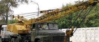
Model KDE-163 belongs to a series of railway cranes equipped with a diesel-electric drive. The machines are supplied with booms of various lengths and configurations and are used to move piece goods. It is possible to use grab grips for loading tree trunks, as well as magnetic units that allow you to reload rolled steel waste.
Models
All models of KDE series cranes were produced by a machine-building plant located in Leningrad (now St. Petersburg). The equipment has been mass-produced since the late 60s and has a load capacity of 16-25 tons.
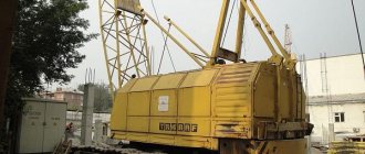
The machine is based on a steel frame welded from a large number of longitudinal spars and transverse beams. Ballast weight and additional equipment are placed in the free space. The end parts are equipped with railway automatic couplers designed for transporting the unit as part of a train.
The chassis consists of 2 paired bogies with spring shock absorption. The trolleys are equipped with traction motors with multi-stage gearboxes, which can be switched while the crane is stationary. The energy source is a diesel generator located on the rotating part of the machine. The transmission of electric current is carried out through slip rings installed in the rotary chase.
The braking system includes standard trolley mechanisms that press the pads against the outer running surface of the wheels. When moving in a hitch, the brakes are connected to a common network; they are controlled by the train driver. Additionally, a mechanical drive of the blocks is installed, which is used when the crane unit is parked.
KDE-163
The KDE-163 railway crane is designed for loading materials and parts weighing up to 16 tons. The basic model was supplied with a 15 m boom and a hook grip. On a separate order, the plant equipped the machine with additional lifting devices and a boom extension insert 5 m long. When using an extension, it is allowed to move loads only with a hook.
The diesel generator DG 75-3 is located on the turntable. The installation is equipped with a forced liquid cooling system. To ensure temperature conditions during long-term operation, an oil cooling system is used. The radiators are installed in 1 block, blown by a multi-bladed fan with a mechanical drive. The standard equipment includes an electrical cable for connecting to an external power source.
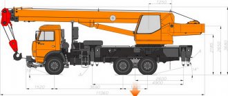
Technical characteristics and dimensions:
- trolley base - 1850 mm;
- the distance between the centers of the trolleys is 2950 mm;
- hitch height - 1040 mm;
- installation length (excluding boom reach and couplings) - 7016 mm;
- width - 3120 mm;
- hook lifting height - 13.7-18.5 m;
- transportation speed - up to 80 km/h;
- weight - 63.93 tons.
KDE-253
The KDE-253 crane with a lifting capacity of 25 tons is built on the basis of components of the previous model. The difference is the increased size of the running platform and the reinforced design of the boom equipment. The electrical circuit and energy sources remain unchanged.
Description of crane parameters:
- load lifting speed - 5.3-17.8 m/min;
- the time required to raise the boom to the maximum is 55-60 seconds;
- platform rotation speed (smoothly adjustable) - 0-1.5 rpm;
- self-propelled speed – up to 8 km/h;
- curb weight - 66.41-67.18 tons.
KDE-251
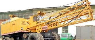
The KDE-251 crane, as standard, has a lattice boom 15 m long, designed to move a load weighing 25 tons. The boom has a detachable design, allowing the installation of additional sections that increase the length of the unit to 20 or 25 m. When using a boom of maximum length, a jib is installed, having a size of 5 m. In this case, the machine is equipped with a hook cage designed for a load of up to 7.5 tons.
The cranes are equipped with a diesel unit DG 75-3, developing a power of 115 hp. The design of the unit includes an alternating current generator. Asynchronous motors with a power of 3.5 to 30 kW are mounted in the chassis design and on the lifting winches.
Crane characteristics (when installing a 15 m long boom and working on supports):
- boom radius - 4.5-14.0 m;
- load capacity range - 5-25 t;
- hook lifting height - 9.0-13.5 m;
- load lifting speed - up to 12.5 m/min;
- rotation speed of the moving platform - up to 2 rpm;
- travel speed - up to 25 km/h;
- installation weight - 69 t;
- base - 4000 mm;
- track width - 1524 mm.
KDE-161
The KDE-161 crane is designed for moving piece goods weighing up to 16 tons. The power plant includes a 6-cylinder diesel engine K-661, equipped with a mechanical supercharger. The motor is equipped with a special coupling that transmits torque to the rotor of a 3-phase ECC5-93 generator.
- boom length - 10 or 15 m;
- load capacity without supports - no more than 10 tons;
- travel speed - 10.2 km/h;
- engine power - 115 hp at 1500 rpm;
- permissible radius of curvature of tracks - 60 m;
- curb weight - 52.1 tons.
During operation, it is possible to connect the machine to a 3-phase industrial power supply network with a voltage of 380 V. For switching, a distribution board mounted on the chassis frame is used.
Railway crane KDE-163
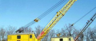
Railway crane KDE-163
– further development of one of the first Soviet diesel-electric railway cranes KDE-151, produced since the early 60s of the last century. The KDE-163, produced since 1971, took into account the shortcomings identified during the operation of previous models, and then the machine turned out to be more productive and economical. Despite the fact that the purchase of a KDE-163 railway crane means that the machine is at least 30 years old, these cranes can work for a long time and, so to speak, are in excellent shape and will work, with proper operation and regular maintenance, for the same amount of time.
Similar advertisements
Railway crane EDK 300/2, 1990, 60 tons Lattice boom. The EDK 300/2 crane is used on railways. d. tracks of stations, industrial enterprises,...
2
Railway crane EDK-1000/1. IN PERFECT technical condition. Price 3,000,000 rubles including VAT. Location: Krasnoyarsk.
3
Price
1 000 000
RUB/t
wholesale 950,000 – 900,000 rub/t
Railway crane SRK-20. New, from storage. In a warehouse in the village of Kerzhenets, Nizhny Novgorod region.
show more
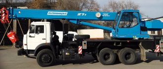
Description of KDE-163
KDE-163
– diesel-electric railway crane, with a lifting capacity of 16 tons (with extended additional supports). The KDE-163 power plant is a K-661 diesel engine combined with a flexible coupling and a DG75-3 generator. Thanks to the presence of a multi-engine diesel unit, the crane can move independently, even over fairly long distances, but it is much more economical to transport the crane as part of a special train. If necessary, this railway crane can itself become a source of energy for other machines and mechanisms, which is very convenient if you have to carry out large-scale work in an area that does not have a centralized power supply.
KDE-163
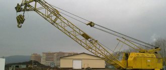
is equipped with a 15-meter steel lattice boom with a box section. An additional section can extend the boom up to 20 m. A boom with an extension can only carry a hook clip; without extension, it can be equipped with an electromagnetic gripper, a two-tooth grab and a special hook for loading timber. When purchasing a KDE-163 railway crane, take care of additional working equipment; this significantly expands the capabilities of the machine and allows you to replace several pieces of equipment.
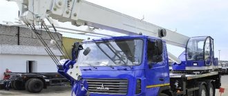
KDE-163 consists of two platforms:
- a chassis that moves on rails and carries hydraulic stops to increase the stability of the crane;
- rotary, on which all the working parts, the power plant, and the driver’s cabin are installed.
The connection between the platforms is carried out through a rotary support - a large-diameter bearing, which has a gear ring on one of the half-rings for engagement with the gearbox and transmission of torque to the rotary platform. The platform rotates using a separate electric motor. The double-drum cargo winch also has its own electric motors (one for each drum, the power of each engine is 22 kW). The boom lift winch is also equipped with a separate electric motor with a power of 14 kW.
The crane's running platform is a steel frame mounted on two carriage trolleys. For a 55 tonne machine it is very important to have reliable brakes. KDE-163
has 3 types of brakes.
Some are connected when the crane is moving as part of a special train, others operate when the crane is moving under its own power, and during long stays the KDE-163
is blocked by a special shoe brake placed on the frame.
TOP-2 crane installations of KZhDE
The KZhDE-16 Pervomaets crane installation, installed on a railway platform, is designed for operation on tracks with a Russian or European standard gauge. The equipment can move loads using a hook, work with a grab tool, as well as with an electromagnetic load gripper. The machines have been mass-produced by the Kirov Machine-Building Plant since mid-1985.