Having laid out a new set of wires in a free place, its orientation will immediately be noticeable: The longest and thinnest bundle is intended for the rear part; The shorter one is for the interior; The largest number of wires and connectors is for the engine compartment. But it holds stable. If there is not enough charge, or it is completely absent, there may be several reasons for such problems: the brushes in the brush assembly are worn out; there are breaks or short circuits in the armature winding; these same defects are present in the stator winding; The diode bridge is faulty. How to connect a generator.
Already at idle speed the generator begins to produce voltage. Let's put the removed generator on the table and turn it by the pulley; if you hear a rumble, then the bearings need to be changed. Installation of wiring on a Gazelle car Wiring on a Gazelle is divided into the indicated zones. Summary Although there is still time before winter, you should worry about the electrical components of your Gazelle in advance.
Well, everything is in place, everything is connected, the first launch and everything works, great! The rear bearing is rigidly pressed onto the rotor shaft, and it is practically impossible to do without a puller. Also, through the charge lamp, the generator is initially excited at the moment it starts working.
Replacing the regulator relay on a UAZ 469
Generator connection diagram for VAZ 2107
Namely, to correctly adjust the operation of the ignition system elements. The voltage should be 13.6 - 14 Volts; when the headlights and heater are turned on, it should not drop below 13.4 Volts.
If it starts normally, then the starter and wiring are normal.
On the other hand: I have repeatedly noticed, especially when starting is difficult, on a connected battery the voltage after start is about 15.1 V, which is clearly more than normal.
Replacing the pulley.
The battery becomes a consumer and charging begins, the excitation winding of the generator is powered through the same circuit, only now not from the battery, but from the generator output. If there is a breakdown or break, then the winding will have to be replaced; it’s easier to replace the generator. Check the rotor winding. The rotor shaft rotates in ball bearings installed in the covers. Calling an electrician he knew, he said two cherished words and everything fell into place - Put on the light bulb! After this procedure, I had to straighten the impeller a little. This device was sufficient for breaking and tightening the nut. How to connect a generator to ZMZ 402
Wiring diagram UAZ 3303
- Installation of a 90 Amp generator in a UAZ 469
- Transfer of the generator to the top of the UAZ-469 (417 Engine) UAZ 3151
- Replacing the UAZ 3962 generator
- Generator ZIL 131 in UAZ 469
Installation of generator 90 AmPuAZ 469
After the first use of the winch, the native (USSR) 40A generator stopped charging the battery. A 90 Amp generator from a steer was found in the garage. The mount is the same as on the UAZ. This generator has been sitting for 5 years and it is not known what condition it is in. If you don't put it, you won't know. A voltage regulator (hereinafter referred to as RN) from Volga (13 3702) was purchased. In order for the new generator to fit correctly into place, you need to install a pulley from the old generator on it. It was not possible to remove the pulley from the Soviet generator manually and using a screwdriver.
Generator 2022.3771 for UAZ-3151x with ZMZ-402 engine
The easiest part in terms of connection is the rear part of the car, where you only need to secure the harness and connect the rear lights and the fuel level sensor in the gas tank.
The rear bearing is rigidly pressed onto the rotor shaft, and it is practically impossible to do without a puller. Current passes through the relay coil and the armature begins to attract, and the contacts open. Note! Current is supplied to the field winding through brushes pressed against the rotor rings. If it starts normally, then the starter and wiring are normal. Drawdown to 12.1. If there is not enough charge, or it is completely absent, there may be several reasons for such problems: the brushes in the brush assembly are worn out; there are breaks or short circuits in the armature winding; these same defects are present in the stator winding; The diode bridge is faulty. If there is a break in the winding, or a breakdown to ground, the rotor must be replaced. At the same time, trying to deal with the lack of generator power at idle speed, it was cured by pulling and cleaning all the power wiring, ground, as well as replacing the power fuse block, the diode bridge and RR turned out to be not to blame, I dug up an elegant and outrageously simple solution on the Internet. I will not consider options for “reversing the polarity” of the excitation winding, since the real return from such an operation is low. Three additional diodes provide power to the voltage regulator, which in turn transmits it to the excitation winding of the generator.
Generator device
I repeat, on older models it is more correct to connect powerful loads directly to the generator. The rear bearing is pressed onto the rotor shaft and is pressed by the rear cover through a plastic sleeve. The higher the speed, the greater the EMF, which means the voltage can rise to unacceptable values. I give the load: long range, heater, heated glass, I also turned on the emergency lights.
The higher the speed, the greater the EMF, which means the voltage can rise to unacceptable values. The needle on your own voltmeter should be on the green scale.
Since the belt drive also ensures the rotation of the water pump, when the generator belt is too tight, noise appears from the bearings of the pump and the generator itself. A device that maintains voltage at the same level is called a voltage regulator. Generator 90A for UAZ - G287
basic information
Fuses in a UAZ Bukhanka car are located in a special mounting block, which in turn is located in the air inlet box on the left side of the vehicle. The mounting block includes all the most important sections of electronic circuits, while supplying them with the necessary fuses and relays. The fuse box of the UAZ Bukhanka car consists of two lines with fuses and this entire structure is secured with a nut to the vehicle body. If you decide to remove the fuse lines, you will need to disconnect the battery.
The main elements of the electronic circuit include:
- Accumulator battery;
- Electronic fuel pump;
- Fuel mixture purification filter;
- Injectors;
- Engine control unit;
- Electronic ignition coil;
- Spark plugs;
- Idle speed sensor;
- Crankshaft sensor;
- Air damper sensor;
- Tachometer;
- Fan motor cooling the radiator;
- Electronic fan motor control relay;
- An indicator that monitors engine performance;
- Diagnostic connector.
Wiring diagram UAZ Bukhanka
If any failure of electronic equipment occurs, the current in the node that is responsible for this device will increase, resulting in a short circuit. The wire through which the current passes to the fuse burns out and melts, as a result of which the circuit breaks and the device turns off, but its integrity is maintained. That is, thanks to fuses, the main parts are protected from overheating in the event of a short circuit.
How to properly remove and install the mounting block?
If the electrical circuit is made with high quality, it will greatly facilitate the process of installing and removing electronic equipment. So, the algorithm for removing the mounting block:
- Disconnect the wiring from the negative terminal of the battery;
- Open the hood and remove the cover from the fuse and relay box. To do this, you need to press out 4 plastic latches;
- Move the rubber cover;
- Disconnect the upper block of the wiring harness from the block;
- We unscrew the 2 nuts that secure the block;
- We take out the block from the compartment, which is located in front of the windshield;
- We disconnect the lower blocks of the wiring harnesses from the block;
- Install fuses and relays in reverse order.
About classic UAZ SUVs and off-road vehicles
In subsequent models, the tachometer received a signal from the ignition system, and the generator phase output was no longer needed; if the generator has one, it is simply not connected.
The video above just shows the option of starting a car unprepared for winter. The generator rotor is driven by a V-belt from the engine crankshaft pulley. Similarly, the excitation winding receives power through the brush voltage generator.
But there were some bugs. Summary Although there is still time before winter, you should worry about the electrical components of your Gazelle in advance. That is, the battery begins to charge at lower speeds than in the standard version.
The starter turns hard, cannot start the engine and there is not enough battery for the second attempt. All this can be avoided if you know what exactly you need to do... Technical aspects of winter operation The most obvious and pressing issue after a cold night in the open air is starting the engine. I give the load: long range, heater, heated glass, I also turned on the emergency lights.
- Wiring diagram for generator Gazelle 406 injector. Gazelle electrical circuit diagram
Read additionally: Install a two-gang switch with grounding
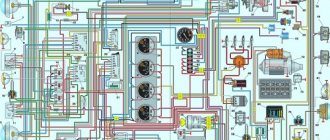
22.8. Electrical circuit diagram with ZMZ-402 engine
Installation kit: generator Thus, repairing a generator means replacing the diode bridge and replacing the bearings; in other cases, it is more profitable to exchange it for a reconditioned one. The reliability of the excitation circuit does not increase: the relay-regulator is still critical to a good “ground”.
Before removing the generator, let's check it again. So, ordinary power relays come to our aid.
The conclusion from here is this: the standard ZMZ ampere generator almost does not work at lower speeds. Calling an electrician he knew, he said two cherished words and everything fell into place - Put on the light bulb! Generator First you need to install a test battery.
Voltage regulator type The generator rotor is driven by a V-belt from the engine crankshaft pulley. Generator brushes Voltage regulator The generator must provide a constant voltage level to the network. By the way, the Gazelle Business wiring diagram is also not immune from such cases. Three-level generator voltage regulator. Three-level generator voltage regulator.
Did you like the article? Follow our channel for new ideas of useful car tips. Subscribe to us in Yandex.Zen. Subscribe.
Having become an indispensable vehicle, the Gazelle with the 402 engine still requires attention over the years.
Native 402 engine for Gazelle
Equipped with a ZMZ-402 carburetor engine, the car successfully exhausts its service life, and when the time comes for a major overhaul, many owners think not only about restoring, but also about reconfiguring its operation.
And since carburetor versions of power units have become a thing of the past, the question of the prospects for using a restored engine is urgent.
- How to enable locking on UAZ Bukhanka
Other section materials
| Generator |
| Checking and replacing Iskra generator brushes |
| Design Features |
| Removing and installing the generator on cars with a gasoline engine |
| Design features of the Bosch generator for a diesel engine |
| Possible generator malfunctions, their causes and solutions |
| Checking and replacing generator brushes 9422.3701 |
| Replacing the alternator drive belt |
| Disassembly, troubleshooting and assembly of generator 9422.3701 |
| Disassembly, troubleshooting and assembly of the Iskra generator |
Electrical system of a Gazelle car
The transition to multi-valve injection engines is possible and even recommended by the automaker, but owners are not always satisfied with this approach, especially from the financial side.
Advice: Be that as it may, when removing the motor for overhaul, the owner has the opportunity to replace the old electrical wiring.
If the resource of the restored power unit inspires optimism, and you have a Gazelle wiring diagram at hand, the 402 engine may well last for hundreds of thousands of kilometers.
Electrical wiring diagram for Gazelle 402 engine
Replacing wiring on a Gazelle car
The reasons causing the need to replace the electrical wiring according to the diagram in Gazelle cars are not only due to the overhaul of the power unit, but also:
- Due to natural wear and tear of wires;
- Delamination of insulation due to natural aging;
- Mechanical damage (kinks, scuffs);
- Short circuits in one or another electrical circuit;
- Oxidation of contacts and connectors.
Additional replacement materials
In addition to purchasing new electrical wiring, those corresponding to the motor used must also be replaced:
- High voltage wires;
- Electronic switch (in later versions of motors of the ZMZ-402 series);
- Ignition coil;
- Battery charge level relay;
- Fuse block contact group;
- Egnition lock.
Places requiring installation work
Laying the wiring harness is not a difficult task, especially since the places for their attachment to the frame are provided initially (gutters, service holes, etc.).
Gazelle interior with disassembled dashboard
However, according to complexity, replacement work is divided into areas of responsibility:
- Engine compartment;
- Vehicle interior;
- Rear part of the body.
Historical reference
Traditionally, the UAZ 469 was produced in two versions:
- Cargo-passenger version – 7 seats and 100 kg of luggage;
- Commander version - 2 seats for passengers and 600 kg of luggage.
For reference: regardless of the version, the UAZ 469 can tow a trailer with a total weight of 850 kg.
Industry standard 1945
According to the old vehicle classification system, in force since 1945, the UAZ 469 was produced under this name, using an alphanumeric name:
- The letter abbreviation UAZ stood for Ulyanovsk Automobile Plant;
- 469 is a serial factory index assigned by the enterprise itself to its models and developments.
For reference: according to the industry standard of 1945, each automobile plant was assigned a specific numbering. For MZMA, which produced Moskvich 408 and 412, these are numbers from 400 to 449, for the Ulyanovsk Automobile Plant these are numbers from 450 to 484, etc.
1966 Industry Standard
Although at the time of the release of the UAZ 469 (1972) a new industry classification system was adopted (industry standard OH 025270-66), the car plant continued to use the name according to the old standard.
However, in 1985, the automaker was forced to change its name in accordance with current requirements:
- the car was assigned a four-digit number - 3151;
- According to the new system, the car can be called in the documentation as UAZ 3151.
For reference: industry standard OH 025270-66 prescribes determining the type of vehicle by engine displacement, length and weight. The first digit indicates the class of the car, the second – the type (truck or passenger car), the third and fourth – the factory model index.
The car plant named all further modifications and new models in accordance with current standards. In particular, the UAZ Patriot, which appeared in 2005, according to the industry classification, received the “correct” designation - UAZ-3163. For greater identification, the factory instructions contained both names.
For reference: the automaker, even in the promotional video for the Patriot model, makes every possible reference to the legendary “ancestor” - the UAZ 469. This model really turned out to be capable of effectively coping with domestic off-road conditions.
Installation of wiring on a Gazelle car
The wiring for Gazelle 402 is divided into the indicated zones.
- Checking the functionality and replacing the oil pressure sensors of UAZ cars with your own hands
Having laid out a new set of wires in a free place, its orientation will be immediately noticeable:
- The longest and thinnest tourniquet is intended for the back;
- The shorter one is for the interior;
- The largest number of wires and connectors is for the engine compartment.
The start of work on replacing the wiring is carried out from the cab:
- We fix the tourniquet in the cabin;
- We drag the second wiring harness under the hood and secure it;
- We drag the rear harness along the frame, connect the connectors, focusing on the colors of the wires;
Electrical part in the engine compartment
In the engine compartment:
- We divide the harness into the right and left sides, focusing on the length and connectors;
- Connect the switch;
- We feed the wire to the generator;
- Connect the voltage regulator;
- Connect the ignition coil;
- We connect the terminals of the windshield wiper, turn relay;
Tip: the Gazelle 402 wiring is divided into colors that correspond to the colors shown in the diagram, as well as on the Gazelle Business wiring.
In the cabin:
- We connect the connector to the fuse block;
- We feed the wire to the heater;
- We connect the light switch to the steering column;
- On the instrument panel, we power the central head light switch, the hazard warning button, and connect the devices.
Conclusions: using the factory wiring diagram of the Gazelle, regardless of the model - 406 or another, you can independently replace the old wires, adhering to the symbols and color designations.
After installing the StartVOLT, LG 03216 generator, the following problem appeared: the car does not stall after turning off the ignition. At first I panic: how the hell can I drown it out? On the first one I abruptly dropped the clutch and that’s it, they stalled.
I came home, searched the Internet and found a topic on UAZBUK about GENERATORS.
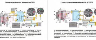
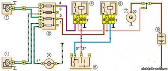
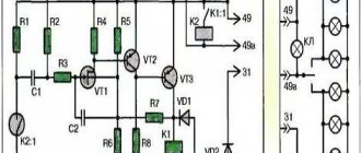
In the first message, point 2 is exactly my case - I have a Relay Regulator (RR) built into the generator. Here is the diagram:
Taken from UAZBUKI, thanks to Udarnik-truda and everyone else who contributes to my (our) mental development.
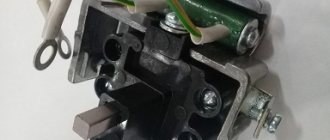
First, I lit a circuit with a light bulb and a resistor (resistor data is 100 Ohm, 2 W), assembled it and tied it to the hoses next to the gene. I decided to find the original light bulb mount and insert it into the panel. And then a bummer awaited me - they are not only available in stores, but also at flea markets. And, secondly, there is a voltmeter on the panel, why is there another sensor, even a light one?
scarce parts
Therefore, I had to look at another diagram from the same point:
Taken from UAZBUKA, thanks to Udarnik-truda and company
I went to the radio parts store again, this time to get a diode (any 50V, 5A). I’ll put it right next to the generator and then I’ll forget about the car that doesn’t stall,
Source
UAZ Generator Repair
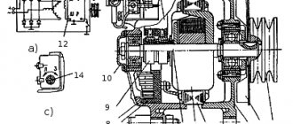
Device
The following devices are found on machines:
- early model G12, producing current up to 20 A;
- G250, equipped with a built-in rectifier, develops power up to 350 W;
- improved 161 3771, equipped with an integrated voltage regulator;
- brushless products model G700A30.
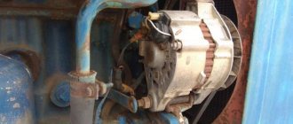
All generator models are mounted on the crankcase of the power unit on the right side with a special bracket. The drive uses a belt stretched between pulleys. The lower support of the generator allows the unit to be moved a short distance, providing drive tension.
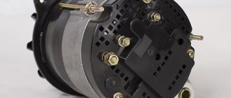
Components:
- Outer casing made of light alloy or steel (on early models). At the ends there are covers in which the rolling bearings are located. The back cover on a number of models is used to install the rectifier unit, brushes and voltage regulator.
- Inside the housing there is a package of steel sheets with a wound wire that forms a 3-phase winding. A device called a stator is used to generate current.
- Inside the stator, a rotor rotates on bearings, on which steel bushings and an excitation winding are placed. The wire leads are attached to the collector. On the outside of the stator there is a shaft with a recess for a key, which is used to mount the drive pulley. The part is secured with a nut. An impeller is installed in front of the pulley to supply cooling air inside the device.
- A spring-loaded brush assembly is used to supply excitation voltage.
- The rectifier bridge consists of 6 diodes.
How to connect
The generator connection diagram depends on the device model. There are 3 wiring connection points on the G12 housing. The terminal with the letter I is connected to the positive brush, and the output of the excitation winding is connected to contact K. The negative brush and the other end of the winding are closed to the generator housing. Terminal M is used to install a wire leading to a separate regulator relay block.
The improved device model G250 has a different connection diagram. For excitation, a rotor winding is used, which is connected to the battery through a special brush.
The generated magnetic field lines rotate with the armature and cross the stationary stator windings, providing current induction.
At the output of the windings there is a rectifier bridge consisting of several silicon diodes. To connect 161 3771, a similar circuit is used.
Malfunctions and repairs
Common problems:
- Lack of battery charging occurs when the drive belt slips due to wear or low tension. Repair consists of installing a new part and adjusting the tension. Another reason may be wear on the brush assembly, which needs to be cleaned of dirt and carbon deposits. At the same time, it is recommended to inspect and clean the collector; if there is severe wear, the surface is worn away.
- Constant overcharging of the battery occurs due to a breakdown of the voltage regulator or damage to the power circuit of the integrated unit. The burnt part is replaced with a new one.
- Low generator power occurs when the belt slips or the regulator is damaged. It is also possible that there is an interturn short circuit inside the stator windings, which will have to be replaced. It is recommended to check the functionality of the diode bridge.
- Accelerated wear of the brushes occurs when the commutator beats or the surface of the unit becomes oily. Repair consists of grinding the surface and degreasing it with gasoline.
How to check
Testing the generator is carried out using a test device that is connected to the positive terminal and the housing. The voltage should be in the range of 13.5-14.6 V.
The voltage regulator is tested using a lamp and applying increased voltage. You can thoroughly check the generator in a workshop using a special stand.
Replacing the alternator belt
The type and size of the belt depends on the engine model. For example, the ZMZ-409 injection unit uses a poly-wedge part with a length of 1220 mm. To remove the element, you need to loosen the tensioner pulley and then unscrew the generator mount. After this, the belt is removed from the pulleys and a new part is mounted.
To replace the V-belt used on carburetor engines, you need to loosen the generator. After installing the new part, tension is ensured by moving the housing along the guide bracket. It is important to align the generator and crankshaft pulleys in the same plane, which extends the life of the belt and reduces noise during operation.
Source
Connecting a Moskvich generator
What should you keep an eye on?
During operation, the owner of a UAZ Hunter must monitor:
- The condition of the electrical circuit wires, the reliability of their connections, and cleanliness. This is important, because, for example, if the contacts are bad, the voltage in the generator can increase sharply and it will fail.
- Correct tension of the drive belt. If the belt is loosely tensioned, the operation of the generator will be ineffective, and strong tension can lead to destruction of the bearings of the unit.
If problems are detected in the wiring or design of the generator, it is recommended to proceed with repair or replacement as quickly as possible. Usually, for repair work, they turn to specialized service stations, but sometimes you can replace the generator yourself. To do this, you should familiarize yourself with the features of its design.