The power unit in the electric starting system is the starter. Depending on the type of starting system on the MTZ 82 tractor, electric starters are used both to start the PD 10 starting engine and directly to start the diesel engine. As for the starter start of the launcher, we note that they use units of the ST 352 D, ST 362A brands with a power of 0.6 hp. The article will focus on the components installed for electric starting of a diesel engine: their varieties and technical characteristics, advantages and disadvantages, causes of operational problems, features when choosing and purchasing a component.
ST 212A
Starter ST 212 (D 240) of the MTZ 82 tractor
» Electrical equipment » Starter ST 212 (D 240) of the MTZ 82 tractor
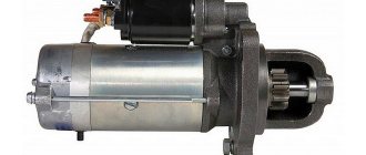
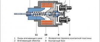
The starter ST 212 of the d-240 engine combines an electromagnetic traction relay, an electric motor and a drive mechanism.
Using the VK 316B switch located on the instrument panel, the starter is turned on. The starter uses a four-pole DC motor, series excitation and 4.8 hp. (3.5 kW).
The housing contains four steel poles with field coils. The starter armature device includes a shaft on which a package of iron is pressed, a winding laid in the grooves of the package and a collector consisting of copper plates isolated from each other. The shaft rotates in three bearings installed in an intermediate support and cover. The bearings are made as metal-ceramic covers, lubricated with oil.
Four brush holders are attached to the cover from the inside. The brushes are pressed against the commutator using springs. The brush-collector unit is protected from dirt by a protective cover.
Power to the electric motor comes from the battery. When current passes through the field and armature windings, electromagnetic fields are created, as a result of which the armature begins to rotate, generating torque. Using the starter drive, torque is transmitted from the starter shaft to the engine crankshaft via the drive gear and flywheel ring gear. The drive is located on the armature shaft and consists of a buffer spring, a gear, a release sleeve and a roller freewheel with a guide clutch.
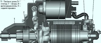
ST 212 starter device: 1 - housing; 2 - anchor; 3 - excitation coil; 4 - brush; 5 — hairpin; 6 — washer; 7 - casing; 8 - cover; 9 - connecting bus; 10 - plunger; 11 - relay pull-in coil; 12 — relay holding winding; 13 — relay anchor; 14 — return spring; 15 — relay flange; 16 — lever; 17 - cover; 18 — persistent half ring; 19 — washer; 20 — clip; 21 — drive gear; 22 — freewheel; 23 — buffer spring; 24 — branch sleeve; 25 — washer; 26 — intermediate support; 27 — outer ring; 28 — roller; 29 — spring; 30 - plunger; 31 — coupling cover.
Freewheel
A freewheel is used to transmit torque in one direction, namely to the engine shaft, ensuring automatic separation of the engine and starter shafts after starting, thus protecting the starter armature from failure due to centrifugal forces. When the starter is turned on, the torque from the armature shaft is transmitted to the freewheel guide sleeve and then to the outer race. Scrolling clockwise, the cage is blocked by the rollers and continues to rotate simultaneously with the cylindrical part of the gear. The rollers are held by springs in the narrow part of the shaped grooves of the outer casing. Thus, the engine flywheel crown and gear rotate simultaneously with the outer race. After the start, the rotation speeds of the gear and flywheel increase. The cylindrical part of the gear carries the rollers along with it, moving them into a much wider part of the shaped grooves of the outer race and wedging the connection, as a result of which the transmission of torque from the running engine to the starter armature is not allowed.
Electrical wiring diagram of MTZ-82.1, color with description
"Belarus" MTZ-82.1 is a new universal agricultural tractor of 2006, which is a modified model of MTZ-82 and can be equipped with a hole drill, hay thrower or plow. In models produced since 2013, the chassis has been improved and a large number of attachments have been added, which can be purchased separately.
When performing electrical equipment maintenance or repairs, most often the required unit is removed or the wiring is partially disconnected; this is where you will need a schematic diagram of the electrical wiring in color, which you can view and download absolutely free!
If you need to disconnect or connect electrical wiring, repair equipment (for example, a generator or battery):
- check the electrical diagram;
- turn off the main switch before starting work (disconnection and connection of plugs should be carried out strictly when the engine is not running);
- do not check the serviceability of electrical circuits using the “spark” method, creating a short circuit;
- Observe the polarity of the battery, carefully connect plus to plus, minus to minus.
What is an MTZ electrical circuit?
Let's look at what the electrical equipment diagram of a Minsk tractor consists of. One of the advantages of Minsk technology is the use of high-quality electrical wiring, based on the fact that metal parts are designed to act as mass. The advantages of such electrical wiring MTZ-1221, 80 or 82 include:
- reduced number of wires;
- simplified approach to maintenance.
But you need to take into account that wiring requires constant care and monitoring.
This will help monitor the serviceability of the wires, their insulation, and the reliability of the fastenings. If damage to the electrical circuit of the MTZ-80 or 1221 tractor is not detected in time, a fire, insulation damage, failure of electrical circuits, etc. may occur.
Let's look at the electrical equipment of Belarus tractors and a description of its operation.
The electrical circuit of MTZ-1221, 80 or 82 has the following characteristics:
- It has a polyvinyl chloride colored surface with low voltage.
- Additional elements are connecting panels, connectors, and wires that can be mounted in bundles. For example, such a half-move is applied to wires in MTZ-82.
- The PS 300A-100 socket is located on the rear wall of the operator's cabin and has 7 contacts.
- The socket is intended for all work where electricity is needed, including when transporting goods.
- Connection to the socket is made via a plug.
- If the need arises, you can connect the wiring harness from other units. Both the plug and the socket have special markings that help you understand where the wires are connected.
Thus, the wiring of MTZ-80, 82 and 1221 is functional and is designed to withstand loads while the tractor is operating.
Starters on MTZ Belarus tractors: design and installation
The simplest device for starting an engine used to be the so-called crank. It was inserted into a special hole, clung to a special terminal of the engine crankshaft and, by rotating it, the engine was spun up to the required speed for starting. Now, in order to spin the engine crankshaft to a frequency that will allow it to start, there is a so-called starter.
Types of starting devices
MTZ tractors use two types of engine starting systems - gasoline and electric.
Electric starter on the MTZ tractor
The gasoline engine is a small, single-cylinder starting internal combustion engine. The manufacturer delivers the PD-10 model from the factory. It consists of a motor and a gearbox. People sometimes call it “launcher”. The launcher's power is only 10 horsepower. Considering that this is a two-stroke engine, a mixture of gasoline and oil is used as fuel. Moreover, you can use low-quality fuels and lubricants - the engine is unpretentious, and this will not particularly affect its performance. After starting the PD-10, the torque is transmitted through the gearbox to the crankshaft of the main engine to spin it up.
Important Technical parameters and design principles of GAZ dump trucks
Electric starter is a direct current electric motor. It is powered through a battery-powered switching mechanism. The manufacturer provides for the installation of ST-142E starters on MTZ tractors. Its design includes the following elements:
- Frame. Cores and windings are placed in it.
- Anchor. The collector plates are attached to the armature axis and the core is pressed into place.
- Solenoid relay. It supplies power to the electric motor and pushes out the overrunning clutch through a movable jumper.
- Bendix. Otherwise, overrunning clutch. Through the meshing gear it transmits torque to the flywheel.
- Brushes and brush holders. Serve to supply voltage to the armature commutator plates.
The operating principle of a tractor starter is the same as the others and consists of three main stages:
- The drive gear is connected to the flywheel ring;
- Start;
- The drive gear is disconnected from the flywheel.
That is, it does not participate in the further operation of the engine. Its main and only task is to start the engine.
In early versions of electric starters, torque was transmitted to the main engine by engaging the drive clutch gear to the flywheel. It was carried out by pressing a spring lever.
Nowadays more advanced mechanisms are used. Modern models use a gearbox for transmitting rotation. Their design uses planetary gearboxes, which consist of several gears. The gearbox amplifies the voltages passing through it several times. This method is more reliable, the starting torque has increased by a third. In addition, the weight of the starter itself has decreased and durability has increased. One of the significant advantages of gear starters is low current consumption during cold starts.
All types of starters are automatically switched off when the main engine starts.
| Model | Rated power, kW | Rated voltage, V | Dimensions, mm | Weight, kg | Manufacturer country |
| Spark | 3 | 12 | 380x150x220 | 14.35 | Slovenia |
| Magneton | 2.8 | 12 | 290x160x120 | 5.3 | Czech |
The factory version provides for the installation of electric starters on the D-240/D-243 engines and on more modern engines; on the D-240L/D-243L there is a starting motor.
Installing an electric starter instead of a starting motor
Depending on the specific operating conditions of the tractor and individual needs, the owners themselves determine the advisability of using either an electric starter or a starting motor. It would be more justified to start the engine using the PD-10 in cold weather, when the fuel has thickened and in order to start the engine, more power and more battery consumption are required. In summer or in warm areas, starting with a conventional starter is a more convenient option.
Reinstallation procedure
When figuring out how to install a starter instead of a starter, it should be noted that the procedure is extremely simple and does not require significant effort from the master. You will need to disassemble the tractor, which will allow you to gain access to the necessary components. After this, it is advisable to adhere to the following algorithm of actions:
Check the condition of the installed flywheel. In most cases, YuMZ equipment has an impressive mileage and requires element replacement
You will also need to make sure that the installed element is a universal type and can be used with a starter. Remove the old flywheel ring, designed to work with the standard starting unit. Warm up the crown that you plan to use with the starter. Place the crown onto the flywheel, being careful not to damage the element. Install the crankcase and the starter.
Such a procedure requires disassembling the tractor, and therefore novice craftsmen may encounter certain difficulties. There is also an alternative method that can significantly simplify the installation process. It involves the use of an already assembled mechanism, which is equipped with a gear starter.
Installing a starter at YuMZ instead of a starter using this method assumes that the tractor owner will only need to dismantle the starter motor and install a new unit in its place. Such kits are somewhat more expensive than individual parts, which is compensated by the speed of installation, which allows even a beginner to cope with the task.
Maintenance and repair of ST 212 starter
Maintenance of the starter consists of keeping it clean, checking the fastening, the condition of the terminals, etc. The starter requires a high current strength, as a result of which even weak transition resistances in its circuit can lead to some voltage drop and a noticeable decrease in power.
It is recommended that the starter be inspected every 3000 hours of operation to identify possible faults. To do this, you need to remove the starter from the engine and clean the outer part of dirt and dust. Next, the protective casing is dismantled and the condition of the brush-collector assembly is checked. If contamination or the slightest burn is detected, it should be wiped with a rag soaked in gasoline. If the burn cannot be removed, then this area can be cleaned with sandpaper. The brushes should move freely in the brush holders and their plane should be adjacent to the commutator. The pressure of the brush spring at the moment the spring separates from the brush body should be 7.5-10 N (0.75-1.0 kgf). Next, remove the solenoid relay cover and inspect the condition of the contacts. If the contacts burn, they must be cleaned with a file and then wiped with a rag soaked in gasoline.
Important TOP 3 domestically produced Celina cultivators
If more serious faults are identified, the starter must be disassembled and the following work must be carried out: clean the housing inside and outside, clean the armature from dirt and dust; grind the collector to a minimum depth until a smooth surface is obtained, and then clean it with sandpaper; inspect the condition of the flywheel ring and drive gear, clean out potholes and worn-out teeth if necessary, or replace them if their service life is exceeded; replace worn brushes up to a height of 10 millimeters with new ones; Lubricate all rubbing parts with engine oil.
The assembled starter must be adjusted and tested in operation. When adjusting the starter, a current of 8-12 V is supplied to the output terminal of the relay windings from a battery or a special device. The starter housing must be securely connected to the negative terminal of the battery. To prevent rotation of the armature, it is necessary to disconnect the tire from the output bolt of the housing. When the traction relay is activated, the gap between the thrust half-rings and the end of the drive gear should be 3±1 millimeters. The gap is adjusted by turning the eccentric axis of the lever, which is then secured with a nut. After assembly, the starter is checked at idle speed. During testing, the armature rotation speed and current consumption are measured, which must correspond to the technical characteristics of the starter - at least 5000 rpm and no more than 120 A.
If the armature rotates tightly, this indicates distortions due to incorrect assembly of the starter, a short circuit of the armature winding to ground, the armature touching the strips or a short circuit between the turns, which leads to increased current consumption. Low current consumption indicates poor contact at the joints or weak brush spring pressure.
Article: 6401.3708600-01
Data updated: 11/01/2021 at 12:00
Characteristics
| Order code | 264877 |
| Articles | 6401.3708600-01T |
| Catalog group | Electrical equipment, ..Electrical equipment |
Options
Shipping territory
Other partner warehouses and stores
+7 [email protected] Shipments only for legal entities by pre-order
Mon-Fri: from 9:00 to 18:00, Sat, Sun: closed
+7 [email protected] Mon-Fri: from 9:00 to 20:00, Sat: from 9:00 to 18:00, Sun: from 9:00 to 16:00
+7 [email protected] OPT: Mon-Fri: from 9:00 to 18:00, Sat-Sun: closed. Retail: Mon-Fri: from 8:30 to 17:30, Sat: from 10:00 to 16:00, Sun: closed
+7 [email protected] Mon: from 8:30 to 18:00, Tue-Thu: from 9:00 to 18:00, Fri: from 9:00 to 17:30, Sat-Sun: closed
Conversion to starter starting according to the version of the manufacturer MTZ
Everyone knows that the components and parts of modifications of MTZ 80(82) tractors are maximally unified and interchangeable. Therefore, the alteration consists of installing on the tractor components and parts from the manufacturer’s plant that correspond to the MTZ 80(82) starting system with electric starter. This option is considered the most expensive and time-consuming, but fully corresponds to the manufacturer’s configuration with this starting system.
Parts and components for conversion to a starter
1 Rear engine plate for mounting the starter.
The part is replaced due to the different location of the mounting holes for fastening the units transmitting rotation to the ring gear with a starter or starter. Also, in order not to completely replace the part, you can get by with a commercially available fragment of a plate for fastening the starter, which is installed with an overlay from the outside in the place where the starter transmission housing is mounted. This ensures the correct location of the starter Bendix drive gear for full engagement with the diesel flywheel.
Factory conversion kit for MTZ 80
2 Replacing the flywheel.
Why do you need to replace the flywheel? — For drive from a starter, the ring gear of the part has a smaller size in terms of the internal landing diameter and the outer diameter, so it is impossible to simply replace the rings without changing the flywheel completely.
To complete the description of the conversion process according to the factory version, we list the sequence of operations:
- The starting motor with the clutch reducer is dismantled.
- The outlet windows of the cooling jacket in the diesel unit for supplying liquid to the starting engine are plugged.
- Roll out the tractor, disconnecting the diesel engine from the housing of the intermediate part of the tractor transmission.
- Remove the clutch basket, remove the flywheel, dismantle the rear plate if it is completely replaced under the starter.
- Assembly is carried out in the reverse order, installing the flywheel with the crown under the starter.
- Install the starter into the seat in the replaced plate or through a fragment of the plate.
to order
Code: B00008047
Manufacturer: ZIT (KZATE)
12 585
Code: 000174819
Manufacturer: ATE-1
7 539
Code: 000022525
Manufacturer: ZIT (KZATE)
to order
Code: 000013184
Manufacturer: Russia
to order
Please tell us about your problem
Thank you! Your comments are very important to us and help us improve our search results for all our customers
As soon as the price of a product drops, you will immediately know about it
Dynamics of changes in the average price for six months
Section under construction
There are no reviews for this product yet. Be the first!
Information about technical characteristics, delivery set, country of manufacture and appearance of the product is for reference only and is based on the latest available information from the manufacturer
By continuing to use our website, you consent to the processing of Cookies and other user data in accordance with the personal data protection and processing policy.
For cooperation, please contact the Sales Department:
Source
Device
The brake system circuit is designed on the principle of independent influence on the drive mechanisms of the wheels of the front and rear axles. The pneumatic vehicle used on MAZ vehicles consists of the following elements:
- compressor;
- compressed air tanks (receivers);
- pneumatic pipelines and control devices;
- brake mechanisms.
Important TOP 3 best McCulloch chainsaws for household use
The vehicle can be equipped with a single or double cylinder compressor. The latter is used on tractors (road trains).
Compressed air is supplied through a pneumatic line to the receivers. Depending on the model, the vehicle can use 3 or 4 air cylinders of different capacities. Each pair of wheels (axle) has its own receiver: front and middle - 40 liters each, rear - 20 liters. The parking system is equipped with a separate 20-liter cylinder.
Here, braking occurs due to friction arising from the contact of the pads located on a stationary caliper to the inner surface of the movable (rotating) drum. It is made of cast iron with a diameter of 420 mm and a working surface width of 160 mm.
The brake pads are made of steel. Friction linings made of asbestos-free material are installed on top. The gap between the pads and the surface of the drum is adjusted by a lever with a built-in automatic adjuster. The front wheel brakes are actuated by diaphragm brake chambers (BC). On the rear axles, the force on the pads is transmitted by spring energy accumulators.
Control air is supplied to the actuators by the brake valve through a four-circuit valve. This applies the brakes on all wheels simultaneously. If there is a trailer, to prevent it from hitting the tractor, a trailer brake control valve is installed, which allows the brakes to be applied slightly faster than on the tractor.
See » Design and characteristics of the MAZ-64229 cabover truck
Maintenance and possible starter problems
Routine maintenance of the unit is performed every 3000 engine hours of tractor operation. During operation, for normal operation of the starter, you need to ensure the cleanliness of the assembly and connecting terminals, as well as the reliability of the fastenings. The operation of the unit is characterized by the consumption of high current, so the appearance of additional transition resistance in the circuit will be expressed in a drop in voltage and output power.
The causes of failures in the operation of the starting device may be:
- wear and uneven operation of the excitation brushes
- burning of the surface of the commutator part of the armature and its contamination,
- burning of the solenoid relay contacts
- short circuit of the armature to ground or damage to the field windings as a result of wear of the support bushings, bearings and general contamination of the unit
- failure of the bendix and drive gear due to wear
Checking the commutator and brushes
To check, the housing is dismantled and cleaned of dirt. Remove the brush holder cover and check the condition of the brushes. If the length of the brushes is less than 10 mm, replace them. The springs in the brush holders must create the same force on the brushes. If there is a discrepancy, replace the springs. In brush holders, brushes should move freely without distortion or jamming. The unit collector is cleaned with a rag soaked in gasoline to remove dust and dirt. If there is slight burning of the collector, clean it with fine abrasive sandpaper. Deeper damage to the commutator can be repaired by grooving to a minimum depth and then grinding to a smooth surface.
If damage is detected to the starter field windings, contact a qualified specialist for repair.
Repair of retractor and drive
To inspect the traction relay, remove the cover of the device and check the condition of the connecting contacts. Clean parts from dirt. If there are burns on the surface of the contacts, clean them or turn the disc contacts back to each other in case of unacceptable damage.
If there are small potholes on the drive gear, the damage is eliminated by filing with a file. In case of unacceptable damage and wear, the parts are completely replaced.
Assembly
During assembly, the bushings and rotation bearings, shaft journals, and screw splines are lubricated. To preserve the working life of the gear starter, the gears of the gearbox are lubricated with a special heat-resistant lubricant, which ensures the preservation of parts under operating heating conditions. Evidence of proper repair and assembly of the unit is the free rotation of the armature without distortions or jamming, with a runout of the commutator of no more than 0.05 mm relative to the shaft journals.
Additionally, pay attention to the starter power cable. With sufficiently long operation, the wire loses its conductive characteristics, and its total resistance increases.
As a result, a significant voltage drop occurs, which negatively affects the starting ability of the starter. For a good start, install a multi-core copper cable with a cross-section of at least 50 mm².
