Troubleshooting in the KamAZ electric starting system
The engine starting system of a KamAZ vehicle can be in three alternative states: serviceable, operational and faulty (failure).
When in good condition, the starting system ensures the engine starts, and the condition of all devices meets the requirements of the technical specifications.
When in working order, the system ensures reliable engine starting, but the technical condition of some devices does not meet the technical conditions.
In the event of a malfunction (failure), starting the engine is impossible due to a malfunction of one or more system devices.
We will not consider the serviceable state of the system, since we are not tasked with determining the failure-free operation period of the system by the number of starts or by the mileage of the vehicle. To perform most tasks, it is enough to have the system in working order, when the system ensures reliable engine starting. Therefore, first of all, we will consider system failure and possible malfunctions, and indicate ways to quickly identify and eliminate them.
The system consists of seven devices, each of which affects the operation of the entire system. Therefore, in order to optimize the troubleshooting process, it is necessary to time each test and evaluate its impact on the performance of the starting system:
Checking batteries
Remove the cover from the battery socket. By external inspection, check the condition of the terminals of the tips and the tightness of their fastening to the pole terminals (Fig. 1). Based on the density of the electrolyte, the degree of discharge of the battery should be determined. Check time is about 5 minutes;
Checking the presence of voltage on the ammeter
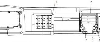
Unscrew the bolts securing the prior shield and tilt the shield towards you or place it on the steering column. In this case, free access to the ammeter leads is available. Connect a test light in series to the input and output of the ammeter. If the light on the “+” of the ammeter is on, then the circuit up to the ammeter is working, and vice versa. Then check the “-” ammeter. If the control lamp is on, it means that current is passing through the ammeter, and faults should be looked for further along the circuit. If the light does not light, then the ammeter is faulty. This test without replacing the ammeter takes up to 2 minutes;
Checking the instrument switch and starter
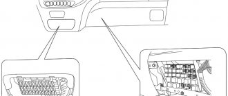
Before checking this device, it is necessary to carry out preparatory work to ensure access to the terminals. To do this, you need to remove the guard panel for the electric motors of the cabin heating system, unscrew the nut securing the instrument switch and starter and remove the device from the panel, leaving it on the wires (Fig. 2). Remove the red wire from the “AM” terminal and check the presence of voltage with a test lamp. If the lamp is on, it means that the circuit to the instrument switch and starter is working. Then you need to connect the red wire to the “AM” terminal, turn the key in the instrument and starter switch to the second position and check the “ST” terminal (green wire) with a light bulb. If the lamp is on, it means that the instrument and starter switch is working properly.
Starter Interlock Relay
This relay is installed under the hinged fuse panel. The relay is assembled on semiconductor devices and it is impossible to check it with a test lamp. A special device is used for checking. A malfunction of the starter interlock relay does not necessarily lead to loss of functionality of the starting system, so this test should not always be performed when troubleshooting;
Checking the starter relay
This relay is located under the hinged fuse panel. Use a wire to connect the “+” from the ammeter to the “K” terminal of the relay. In this case, you should hear a click when the contacts are turned on. In order to make sure that the contacts and relays are closed, it is necessary to connect a test lamp to terminal “C” of the starter activation relay (black wire). If the lamp is on, it means the relay contacts are closing.
Checking the starter traction relay
Use a wire to connect the “+” from the batteries to the terminal that pulls in the starter relay windings. If a click is heard, the relay is activated. The electric motor must rotate. If the starter motor does not rotate, use a test lamp to check for voltage at the contact bolt connected to the electric motor. If the lamp is on, it means that the starter traction relay is working normally.
Checking the starter motor
This check is the most time-consuming, since it is carried out (as a rule) with the starter removed. It takes 30 minutes to remove the starter and 25 minutes to diagnose.
Since the electric starting system has a small number of elements (only seven), the method of element-by-element testing is used, or sequentially dividing the system into two subsystems.
autoruk.ru
Typical starter malfunctions and methods for diagnosing them
The following malfunctions are typical for the starter on KAMAZ:
If situation number 1 occurs, you should check the pull-in winding of the traction relay: an open circuit or short circuit is possible. If necessary, replace the solenoid relays. Also, the cause of the malfunction indicated in point 1 may be a lack of contact between the commutator and the brushes. In this case, it is necessary to replace the brushes or their springs.
If after all these procedures the starter still does not work, then try replacing the PC530 relay; it may have failed.
If the traction relay does not turn on (point 2), you must:
— check the winding of the PC530 relay, if necessary, rewind it; — check the serviceability of the starter switch; — make sure that the pull-in winding on the traction relay is intact (a break is possible). Otherwise you will have to replace the entire relay.
If clicks and knocks are heard when the KAMAZ starter is operating (point 3), you must:
— check the reliability of the contact of the starter traction relay circuit. If there are malfunctions, eliminate them; — make sure that the winding and contact connections of the PC530 relay are in good condition. If necessary, replace the PC530 relay or rewind the winding.
The causes of the malfunction specified in point No. 4 may be the following:
— the closing moment of the traction relay contacts is incorrectly adjusted. To eliminate the malfunction, it is necessary to adjust the gap between the thrust washer and the gear; — clogged ends of the teeth of the flywheel ring gear or starter drive. There are several ways to fix this problem. The first is to replace the drive gear or flywheel crown. The second is to restore the teeth by surfacing. The third is to smooth out the irregularities on the teeth.
If the starter on a KAMAZ rotates the armature, but does not interact with the crankshaft in any way (point No. 5), you must:
— check that the starter is adjusted correctly; — make sure that the teeth of the flywheel ring and drive gears are intact.
The KAMAZ starter is a rather complex device, the repair of which must be carried out on a special stand. If you do not have the necessary equipment and sufficient experience, then it is better to trust specialized service stations.
Where is the starter relay located on KAMAZ?
Kamaz repair
How to check, connect the signal, ignition, starter relay......
Kamaz 2 repair
Long-range. We are starting KamAZ after 6 months of inactivity. Relay repair. Bad mass
Kamaz. Repair.
Starter relay
How to connect a 4- and 5-pin relay. Why?
How to remove the starter on a Kamaz car (Theory)
The starter does not work. The starter does not turn. The starter relay does not retract.
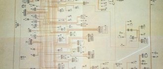
Starter connection diagram
Also see:
- Power of KAMAZ 740
- Where is the candle at KAMAZ
- Repair of Euro KAMAZ shaft
- Tank capacity KAMAZ 55102
- Control fuel consumption of a KAMAZ 6520 vehicle
- Dismantling the KAMAZ compressor
- Pre-launch device for KAMAZ
- KAMAZ days of downtime
- KAMAZ shock absorbers for UAZ
- A number of KAMAZ models
- How to rebuild a KAMAZ engine video
- KAMAZ trucks from state storage
- Truck crane ks 35714 KAMAZ
- Fuel equipment bosch KAMAZ euro 4
- Semiconductor diode KAMAZ
Home » Clips » Where is the starter relay on KAMAZ
kamaz136.ru
Do-it-yourself KAMAZ balancer repair
When repairing a KAMAZ balancer axle or repairing a KAMAZ balancer shoe, it should be taken into account that this axle has a nominal size of 8.8 cm, the shoe bushing is 8.75 cm, and the repair bushing is approximately 8.4 cm. The nominal size of the gap between the bushings and axle - from 0.12 to 0.305 mm, and the permissible maximum gap size between the bushings and the axle is 1 mm. If the bushings move freely, they must be replaced with new ones. We also need to replace the balancer cuff, boot, protective cup and nut, and inject the shoes using a grease fitting.
If cracks are detected in the spring sheets, they must be replaced with main sheets with a thickness of 12 mm (nominal) to 18 mm (maximum). It is recommended to measure the sheet size using a tape measure and caliper to provide the seller with accurate data. When assembling the springs, it is necessary to lubricate the rubbing leaf surfaces with graphite-based lubricant, and lubricate the pins on the front springs. Installation of rear and front springs on a car is carried out in pairs, the difference in deflection should not exceed 1 cm.
KAMAZ balancer axle diagram
Procedure for adjusting the axial clearance of the balancer shoe
- Lift the car by the frame, place it on stands, make it possible to rotate the balancer by separating the ends of the spring located at the rear from the bridge supports, or by removing the spring.
- Screwing the split nut in such a way as to prevent the balancer from turning by hand.
- Unscrewing the nut one-sixth of a turn, tightening the pinch bolt and checking that the balancer can be turned manually; If it is impossible to turn it, you should additionally loosen the split nut, loosening the tie bolt in advance.
In case of replacement, stepladders also need to be measured. During this process, the thread, its pitch, the width of the landing site, as well as the length of the stepladder at this site are measured. When inspecting the reaction rods, you need to take a closer look at the fit of the fingers in the bracket - if free movement of the fingers is detected, they need to be replaced. The seat has a nominal size of 43 mm. In case of higher output, it makes sense to try the fingers from the KRAZ machine. The fingers are syringed using a grease fitting.
Operating principle of the starter blocking relay on KAMAZ
How to connect a 4- and 5-pin relay. Why?
Kamaz 2 repair
Starter Interlock Relay
Starter solenoid relay
Installing an additional starter relay on a VAZ 2112
VEHICLE ELECTRICAL EQUIPMENT.
Installation of Pantera CL 500 alarm system on VAZ 2104, 2105, 2107 (part 3)
3. Charging system - 2
12 to 24 in the MTZ tractor. Standard wiring 12.
Starting modified engine PDM for T 150, DT 75 with a starter from KAMAZ
Also see:
- Gear ratio of KAMAZ winch
- Side view of KAMAZ
- KAMAZ rear fender holder
- KAMAZ pumping oil seal block
- How to determine the KAMAZ model
- KAMAZ onboard 65117 with fassi f 155 0 22
- KAMAZ 6520 average axle play
- Fuel tank 175 l for KAMAZ
- Tire pressure KAMAZ 5350
- Engine KAMAZ 740 power
- How to change a KAMAZ kingpin
- KAMAZ 53229 rear gearbox
- How to remove the KAMAZ 740 starter
- Side view mirror KAMAZ 65115
- Purpose of the KAMAZ 740 diesel engine power system
Home » New » Operating principle of the starter interlock relay on KAMAZ
kamaz136.ru
Device
Structurally, the KamAZ starter is an electric motor with a traction relay and a mechanical drive. This mechanism is installed on the flywheel housing (located on the left side of the engine). It is secured with three bolts and studs.
The mechanism is based on a 4-pole electric motor with sequential excitation. The starter design also includes the following elements:
All this is combined into a metal case. Externally, the KamAZ starter looks as shown in the photo below.
All coils are impregnated with a special varnish and additionally braided with cotton tape. The turns are insulated with cable paper.

