The vast majority of modern cars are equipped with fuel injection systems. There are modifications in which gasoline is sprayed by a nozzle in the intake manifold. There are also models in which fuel is sprayed directly into the engine cylinders.
Diesel units operate differently than gasoline internal combustion engines. In them, diesel is supplied to an already compressed environment in the cylinder. In order for a portion of fuel to be sprayed smoothly, a mechanism such as a high-pressure fuel pump is needed.
Let's consider the features of such a mechanism, its modifications and signs of malfunction.
What is a fuel injection pump and why is it needed?
The mechanism, which is abbreviated as injection pump, is part of the fuel system of a diesel engine, but there are also models for gasoline power units. The only difference between the fuel pump of a diesel engine is that the pressure it generates is much higher than its gasoline counterpart. The reason for this is the fundamental features of the unit’s operation. In the cylinders of a diesel engine, the air is first compressed to such an extent that it is heated to the ignition temperature of the fuel.
When the piston reaches top dead center, the injector sprays fuel and it ignites. The injector needs to overcome enormous pressure. For the system to work properly, the pump must create more pressure than in the cylinders.
In addition to the mentioned function, the pump must also supply fuel in portions, depending on the operating mode of the power unit. This parameter is determined taking into account the rotation of the crankshaft. In a modern car, this process is controlled by an electronic control unit.
Plunger pair design
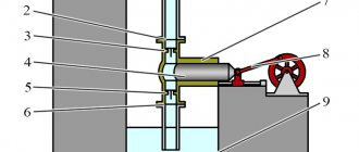
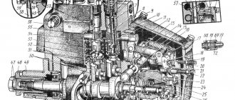
The plunger pair consists of a plunger 9 and a sleeve 8. The sleeve has one or two inlet channels (with two channels, one of them serves as inlet and bypass), which connect the suction cavity to the high-pressure chamber of the plunger pair. Above the plunger pair there is a fitting 5 with a landing cone 7 of the discharge valve. The rack 10 moving in the injection pump housing rotates the gear sector 2, thereby controlling the adjusting sleeve 3 of the plunger. The movement of the rack itself is determined by the crankshaft speed controller. This allows you to accurately dose the cyclic feed amount. The full stroke of the plunger is unchanged. The active stroke and the associated cyclic feed value can be changed by turning the plunger, which is done using an adjusting sleeve.
- Suction cavity
- Gear sector
- Plunger adjusting sleeve
- Side cover
- Discharge valve connection
- Discharge valve body
- Discharge valve cone
- Plunger sleeve
- Plunger
- Injection pump rack
- Plunger driver
- Plunger return spring
- Lower return spring plate
- Adjustment screw
- Roller pusher
- Injection pump cam shaft
In addition to the longitudinal groove 2, the plunger also has a spiral groove 7. The resulting oblique edge on the surface of the plunger is called a regulating edge 6. If the injection pressure does not exceed 600 bar, then one regulating edge is sufficient; for higher injection pressures, a plunger with two regulating edges milled on opposite sides of the plunger. Their presence reduces the wear of the plunger pair, since the plunger with one control edge is pressed under pressure against one side of the sleeve, increasing its production. The plunger sleeve has one or two holes for supplying and returning fuel. The plunger is ground into the sleeve so tightly that the pair is sealed without additional seals, even at very high pressures and low crankshaft speeds. Because of this, only complete plunger pairs can be replaced. The amount of possible fuel supply depends on the working volume of the pair. The maximum injection pressure at the nozzle can be, depending on the design, 400... 1350 bar. The angular shift of the cams on the cam shaft ensures precise alignment of injection with the phase shift of processes along the engine cylinders in accordance with the order of its operation.
a - sleeve with one supply channel b - sleeve with two supply channels
- Supply channel
- Longitudinal groove
- Plunger sleeve
- Plunger
- Bypass channel
- Regulating edge
- Spiral groove
- Annular groove for lubrication
PLUNGER PAIR WITH DRIVE
a — BDC of the plunger b — TDC of the plunger
- Cam
- Video clip
- Roller pusher
- Lower return spring plate
- Plunger return spring
- Upper return spring plate
- Plunger adjusting sleeve
- Plunger
- plunger sleeve
History of development and improvement
This device was first developed in the 1930s by Robert Bosch. In passenger cars, injection pumps began to be actively used in the second half of the same decade.
Since the first gasoline engines were equipped with carburetors, only diesel units needed such a mechanism. Nowadays, gasoline engines with a direct injection system also have a pump of this type (a carburetor is already extremely rare - only in older generation cars).
Although the operating principle of the pump has remained virtually unchanged, the mechanism itself has undergone multiple modernizations and improvements. The reason for this is the increase in environmental standards and performance of internal combustion engines. At first, a mechanical injection pump was used, but it was not economical, which led to large emissions of harmful substances. Modern electronic pumps show excellent efficiency, which allows transport to fit within environmental standards and satisfy drivers of modest means.
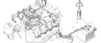
High pressure pump design
There is a wide variety of modifications of fuel injection pumps for gasoline engines, as well as diesel analogues. However, in most cases, the main elements of a mechanical pump are:
- A filter is installed at the inlet in front of the pump;
- A plunger piston located in a cylinder - the so-called. plunger pair;
- A housing in which recesses are made - fuel is supplied through them to the plunger pair;
- Shaft with cam and centrifugal clutch. This element is connected to the timing pulley using a belt drive;
- Plunger pair drive pushers;
- Springs that return the plunger piston back;
- Supercharger valves;
- Mode regulator – connected to the gas pedal;
- Injection pump return valve (through it, excess fuel is supplied to the return);
- Low pressure pump (pumps fuel into the pump).
As already mentioned, mechanical pumps are gradually being replaced by electronic modifications due to their cost-effectiveness and efficiency. The mechanism itself is difficult to repair and adjust. Electronic pumps are equipped with their own control unit, as well as several electronic valves and sensors.
Most electronic injection pumps have their own diagnostic system, thanks to which the device adapts to any malfunctions and errors that arise. This allows the device to operate properly even if one of the sensors fails. Such a pump stops working completely only if the microprocessor breaks down.
Principle of operation
The injection pump operates on the principle of a two-stroke engine. Due to the rotation of the shaft with cams, the plunger piston is driven. Diesel oil enters the sub-plunger space, which then goes into the main line.
The operating principle of the plunger pair is described in more detail in the video:
Plunger pair for UTN
Pressure is created in the cavity, due to which the discharge valve opens. Diesel fuel flows through the fuel line to the nozzle and is sprayed. The pump to the injector supplies only part of the fuel. The remainder is returned to the fuel tank through the drain valve. To prevent fuel from returning from the system when the supercharger is opened, a check valve is installed in it.
The injection moment is determined by a centrifugal clutch. The mode regulator (or all-mode regulator) determines the amount of the supplied portion. This element is connected to the gas pedal. When the driver presses it, the regulator increases the volume of the portion, and when it is released, the quantity decreases.
In electronic models, all processes are controlled by a control unit. Electronics distributes the moment of fuel supply and its quantity, taking into account the dynamics of the car. Such fuel systems have fewer parts, which increases the stability and reliability of the mechanism.
Electronic injection pumps are capable of dividing a portion into two parts, which ensures more efficient combustion and smooth running of the piston group. As a result, there is less exhaust toxicity and increased engine performance. To ensure two-phase injection, the pump control unit records:
- Pressing the accelerator pedal;
- Timing camshaft speed;
- Temperature in the engine cooling system;
- The speed of the car itself;
- The pressure created by the turbocharger;
- Operation of injectors;
- Triggering of glow plugs.
Fuel pumps with suction throttling
Fuel pumps with suction throttling have a throttling needle 8 at the suction window (Fig. c). The needle is connected to a screw under the influence of the diesel regulator. Using lever 10, you can change the throttling section, and therefore the filling of the pump cavity. This pump works as follows. When the plunger moves downward, a vacuum arises in the space above the plunger, which is filled with fuel vapor. After the suction hole is opened by the plungers, this space is filled with fuel. The higher the shaft rotation speed, the stronger the vacuum above the plunger, the greater the resistance of the throttling section to the passing fuel, the shorter the time interval during which the suction window remains open, the less fuel will enter the pump cavity.
The speed characteristics of this pump have a hyperbolic form. At low speed conditions, fuel manages to fill the space above the plunger of the pump, so the pump flow increases, and at a high shaft speed, a decrease in the time-section of the inlet window and an increase in the hydraulic resistance of the throttling section cause a reduction in flow.
This method of regulating cyclic flow is used mainly for low-power diesel engines and in distribution-type pumps.
The pump is characterized by a simple design of the plunger and control device, and has a satisfactory flow rate characteristic. The disadvantages of the pump include:
- the difficulty of regulating the uniformity of supply in multi-cylinder diesel engines, when a needle is installed in each section of the pump;
- low pressure at the start of feeding and lack of a clear cutoff at the end of feeding;
- reduction of supply pressure when diesel load decreases;
- a significant drop in cyclic feed at increased speeds;
- difficulty in regulating supply phases under different diesel operating modes.
Types of injection pump
Fuel systems come in three types:
- Single injection. This is the very first modification. The representative was originally a carburetor. In its cavity, the fuel-air mixture was prepared and supplied to the intake manifold. A little later, such systems, instead of a carburetor, received one nozzle, which injects fuel into the intake manifold, where it is mixed with air;
- Multipoint injection. This is already a type of injection system. An individual injector is installed on the intake manifold for each cylinder. Injection is also carried out into the intake manifold, only as close as possible to the intake valve;
- Direct injection. As the name of the system suggests, fuel is sprayed directly into the cylinders at a time when the air in them is already compressed by the piston.
There are three types of similar mechanisms that can be used in these types of fuel systems:
- Row;
- Distribution;
- Mainline.
In-line injection pump
An in-line injection pump consists of several pumps housed in one housing. Each of them serves a separate injector. This modification was used in old diesel engines. The operation of the entire mechanism strictly depends on the timing drive.
The in-line modification has been used for quite a long time. Even some modern cars (trucks) are equipped with such pumps. The reason is their high reliability and unpretentiousness to diesel quality.
The row system works as follows. The plunger pair is driven by turning the crankshaft. One revolution of the pump camshaft corresponds to two revolutions of the engine crankshaft.
The plunger mechanism, through the fuel shut-off valve of the injection pump, separates part of the fuel from the common line and compresses it in the pressure part of the system. The portion volume is regulated by a gear bar connected to the gas pedal. In cars with an ECU, it is regulated by a servo drive that responds to signals from the control unit.
The injection moment is determined by the crankshaft rotation speed. The mechanism has two coupling halves, which are separated by springs. When the engine speed increases, the springs are compressed, causing the pump shaft to rotate slightly, which leads to a change in the injection advance angle.
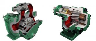
Distribution type injection pump
Unlike the previous modification, this model is smaller in size. It is also characterized by stable operation. There are several modifications of distribution pumps. There are plunger and rotary types. They also differ in the type of drive - internal, end or external arrangement of cams.
A drive with an external cam arrangement is not stable or reliable. Therefore, if possible, it is better to focus on the other two types.
Such pumps wear out faster, since one plunger mechanism in them serves all the nozzles of the group. In this regard, in-line analogues have advantages. Due to their small size, distribution injection pumps are installed in fuel systems of passenger cars and small trucks.
Main fuel injection pump
Unlike the two previous modifications, the main pump creates pressure in a single line - the so-called fuel rail. It serves as an accumulator in which constant fuel pressure is maintained.
Thanks to the smaller number of distribution mechanisms, this modification has proven itself to be the most reliable. Repairing main-line injection pumps is not particularly difficult. The portion volume is controlled by an electromagnetic dosing valve. Such pumps are found in Common Rail fuel rail systems.
Common Rail injection pump
A slightly different type of high pressure pump is used in the Common Rail fuel system. The design of the injection pump is affected by the operating features of the system itself.
Single-plunger Common Rail injection pump
In this system, the injection is controlled and controlled by the computer, so the dosage and timing of fuel injection are not part of the pump's task. It has only one function - to pump fuel into the ramp (battery).
Therefore, the design of the injection pump is greatly simplified. In fact, the pump consists only of a shaft, plunger pairs (from 1 to 3) and valves - inlet and discharge. There are no regulators here as they are unnecessary.
Double plunger high pressure pump
Everything is simple here - the shaft rotates from the drive and the plungers constantly pump fuel into the ramp. This is all that is required from the injection pump.
Is there a fuel injection pump on a gasoline engine?
Although the main use of fuel injection pumps is in diesel engines, many modern gasoline engines also operate by supplying fuel under high pressure. These mechanisms are used in internal combustion engines with direct injection.
GDI gasoline engines require the installation of such pumps. In fact, this system is a hybrid version that combines the design of a gasoline internal combustion engine with the operating principle of a diesel unit. The only difference is that ignition does not occur due to the temperature of the compressed air, but thanks to the spark plugs. Such engines use an in-line modification.
Regulating cyclic feed
The amount of cyclic fuel supply can be adjusted by changing the active stroke of the edge. To do this, the rack 5, through the adjusting sleeve of the plunger, turns the plunger 3 itself in such a way that the adjusting edge 4 can change the moment of the end of injection and, at the same time, the amount of cyclic feed (control at the end of injection). In the extreme position corresponding to zero feed (a), the longitudinal groove is located directly in front of the bypass channel. As a result, the pressure in the high-pressure chamber of the plunger pair during the entire stroke of the plunger is equal to the pressure in the suction cavity and fuel injection does not occur. The plunger is brought to this position if the engine must be stopped. With an average feed (b), the plunger is installed in an intermediate position (along the control edge). Full feed (s) becomes possible only when the maximum active stroke of the plunger is set. The transmission of motion from the rack to the plunger can be carried out either through a rack to a gear sector mounted on the adjusting sleeve of the plunger or through a rack with guide splines to a pin or spherical head on the adjusting sleeve of the plunger.
a - zero feed b - medium feed c - full feed
- Plunger sleeve
- Supply channel
- Plunger
- Plunger adjusting edge
- Injection pump rack
Basic faults
Although injection pumps differ in their design, there are several important rules that the car owner must follow in order for the pump to serve its allotted time:
- Most pumps are sensitive to fuel quality, so it is necessary to comply with the requirements set by the manufacturer for a specific pump;
- Due to the complexity of the design and the loads placed on the mechanisms, high-pressure pumps require regular maintenance;
- All rotating and rubbing parts must be well lubricated, so it is extremely important to follow the manufacturer's recommendations for choosing lubricants.
If these rules are not followed, the device will quickly become unusable, which will require replacement or expensive repairs.
The following factors indicate a malfunction of the injection pump (if other systems are working properly, faults in which may have similar manifestations):
- Black smoke in the exhaust and, as a result, more toxic emissions into the environment;
- Increased fuel consumption (due to fuel leaks);
- Decrease in engine power;
- While the engine is running, noises from the pump are heard;
- Difficulty starting the engine;
- The timing belt often slips;
- Unstable engine speed.
The most common malfunction in such elements of the fuel system is failure of the plunger pair. Most often this happens due to low-quality fuel - plaque accumulates on surfaces, impeding the movement of parts. Also, the cause of mechanism failure is water, which often condenses in the fuel tank. For this reason, it is not recommended to leave the car with an empty tank overnight.
Repair of high pressure pumps
If repairing a regular fuel pump is not difficult - just buy a repair kit and replace worn parts, then repairing and adjusting a high-pressure fuel pump is a very complicated procedure. It is even impossible to determine the cause of the malfunction without additional equipment. Often self-diagnosis of modern control units does not help.
It often happens that the symptoms of a fuel pump failure are identical to malfunctions in the gas distribution mechanism or exhaust system. For these reasons, it is not recommended to repair the injection pump yourself. To do this, it is better to seek help from a specialized service center.
Additionally, watch the video on troubleshooting and repairing fuel injection pumps:
part 1 Repair of fuel injection pump ve 1.6 diesel disassembly troubleshooting