KamAZ Euro-3 generator: connection diagram, how to connect a KamAZ generator, check, price
The KamAZ Euro-3 generator is a mechanism that provides power to energy consumers. Euro 3 is an international environmental standard according to which this mechanism is manufactured.
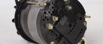
The generator device includes the following elements:
- Stator with winding. Sandwiched between the front and back covers of the entire mechanism.
- Mounting foot and tension eye.
- Covers that are made of aluminum alloys. They are tightened together using 3-4 bolts.
- Ventilation windows through which the air flow is blown by a fan through the generator device.
- Brush unit. Connects to a voltage regulator and a rectifier type unit. The brushes are pressed against the ring mechanism using springs.
- Voltage regulator and rectifier unit.
- Rotor shafts. Made from automatic steel alloy. If roller-type bearings were used in the design, the shafts are made of alloy steel, and the shaft journal is hardened.
- At the end of the shaft there is a hole for a key.
- Contact rings.
- Units that consist of roller bearings with a disposable insert.
Principle of operation
Operating principle of the KamAZ generator:
- The magnetic flux is created by an excitation winding through which a direct electric current passes.
- The magnetic field is generated by a twelve-pole magnet, which is located inside the rotor.
- The winding of the KamAZ generator set is attached to the bushing, and its terminals are soldered to slip rings made of copper.
- Power to the winding mechanism comes from the battery through the starter switch, voltage regulator, brushes and contact rings.
- During the rotation of the rotor mechanism, its magnetic field crosses the winding mechanism with power lines, due to which an alternating current is induced in the conductors.
- Current begins to flow into the three-phase silicon rectifier. After this, the current passes into the external circuit.
- The operation of the generator is monitored using an ammeter, which is located in the driver’s cab on the dashboard.
| Rated voltage level, V | 28 |
| Maximum load current, A | 80 |
| Rotational speed of the rotor mechanism at a voltage of 26 V | If the alternating current is 10 A, then 1300 revolutions per minute. If the alternating current is 30 A, then 15550 revolutions per minute. If the alternating current is 60 A, then 2200 revolutions per minute. |
| Installation power, W | 1000 |
| Fan | Eat |
| Brush holder with voltage level regulator | Eat |
| Material from which the shaft is made | Steel |
| Rotor rotation direction | To the right |
| Number of phases | 3 |
| Number of cycles | 4 |
| Cooling type | Liquid |
| Average fuel consumption | 3.6 l in 1 hour |
| Battery life, hour | 15 |
| Active power of the installation, kW | 18 |
| Length, m | 0,23 |
| Generator diameter, m | 0,174 |
| Rectifier block | Eat |
| Mechanism overload protection | Eat |
| Muffler | Eat |
| Current strength, A | 32,4 |
| Noise level during operation, dB | 85 |
| Weight of equipment excluding pulley, kg | 6500 |
Malfunctions and repairs of the KAMAZ generator
Repair of the generator set is necessary in the following cases:
- The ammeter gives readings of the discharge current at minimum crankshaft speed. In this case, it is recommended to adjust the tension of the drive belt, inspect the rings and wipe them with a cloth soaked in kerosene or gasoline. You should also check the height of the brushes. It should not exceed 1 cm.
- Breakdown in the housing of the rectifier unit. In this case, you need to replace the block with a new one.
- If a short circuit occurs in the rotor, the rotor mechanism must be replaced.
- In case of poor contact in the excitation circuit or if the belts slip, you need to clean the brush holder, check their size and condition. You should also inspect the belts and replace them (if damaged).
- Load current fluctuation. It is necessary to clean the brush holder, inspect the spring mechanisms, adjust the belt tension and the mounting of the vehicle's generator set.
- The charging current is too high. In this case, you need to eliminate the short circuit in the circuit or replace the regulator.
- Increased noise level during operation. The pulley nuts should be tightened and the bearing replaced. It is necessary to inspect the entire mechanism and straighten the bent areas.
- Bearing overheating. Inspect the fan belt; if necessary, adjust its tension.
Principle of operation
In most cases, this problem is caused by a breakdown in the wiring.
The shaft is steel, on its corrugated surface, a steel bushing, pole pieces and slip rings are rigidly fixed by pressing.
Start the engine and check the operation of the new belts. The coils are fixed in the stator core with textolite wedges. The rated voltage of the generator G is 28 V, and the power is VT. And over the years of production, the following were built on its basis in the factory program: Truck tractor; Truck with an extended flatbed; Family of biaxial analogues. If it is not possible to bring the electrolyte density to normal in one go, the adjustment should be repeated.
In addition, the reason may be a failed generator. The driver of the scow tells us in his hearts how the owners of this machine, which transports metal and brings in a good income, try to save on repairs by sending the vehicle on its journey over and over again.
The electrical circuit for connecting the generator to the ROOV electrical equipment system is intended to prevent excitation of the generator when using the EFU electric torch device. Interior lighting system The system is designed to illuminate the driver's workplace, instrumentation, and the vehicle's cargo platform. The rectifier unit converts alternating voltage into direct voltage, and when it becomes greater than the battery voltage, the generator will begin to power consumers and charge the battery.
At charging stations, batteries that are brought into working condition, as well as those removed from cars, are charged, as a rule, at a constant charging current. Each phase consists of series-connected coils wound with enamel-insulated wire. Apply a voltage of 13 V. The waterproof design of the generator is ensured by the use of appropriate coatings on the surface of its parts and impregnation of the windings with waterproof varnishes.
The regulator has four terminals. When the rotor rotates, the magnetic field will also rotate, which, crossing the stator windings, will induce an EMF in them. Checking the generator G 288 (g287) KAMAZ, URAL, KRAZ with a built-in relay regulator
Purpose of the device
KamAZ vehicles are equipped with an electrical circuit built according to the classical scheme with one cable. This configuration provides one cable for consumers; cable number two is the frame of the machine. The effective electric field in the KamAZ vehicle circuit is 24 volts, an indicator achieved through the use of batteries and a device that generates electrically ordered movement of particles.
Generating device 4502.3771, Euro (3.4):
A generator is a mechanism that generates electrically ordered movement of particles and transmits the created product to the wiring of the machine. The purpose of the machine mechanism is to power consumers during the operation of the power unit and, in parallel, to transfer charge to the batteries for further accumulation.
The mechanism that generates the electrics of a KamAZ vehicle operates after the torque reaches 1000 rpm or higher. The initial stage of starting the engine is accompanied by the extraction of energy from the battery; the generating device comes into operation later.
As a rule, KamAZ automobile generating devices are equipped with a rectifier and a voltage regulation mechanism. The rectifier converts the three-phase alternating current generated by the generator into direct mains current. The voltage regulator smoothes out values that change due to differences in engine speed. You can also read about How to start a KamAZ: Instructions.
Connection Guide
To provide power to energy consumers, a generator is installed on the vehicle; KAMAZ can be equipped with a generator that meets the requirements. The article describes the device, provides technical characteristics, possible problems, as well as ways to eliminate them.
Content
[ To uncover]
[Hide]
Device Description
To successfully connect the generator set, a wiring diagram is required.
Electrical connection diagram
In addition, for proper operation of the installation, you must strictly observe its connection according to the pin diagram:
- the battery and load are connected to the “ ” terminal;
- the vehicle ground must be connected to the “-” terminal;
- terminal “B” or “W” is intended to connect to the instrument switch and starter.
- pin “W” or “~” is the phase pin to which the tachometer and the relay blocking the starter are connected;
- terminal “D” or “D” from additional diodes for connecting a control light.
Price issue
1. Bosch for KAMAZ (price - from 18,990 rubles)
2. G-288-O (price - from 3,795 rubles)
3. G-273 (price - from 2,000 rubles)
Correct connection of the generator "KAMAZ" Euro 2. Connect generator "KAMAZ" Euro 2.
Electrical equipment KAMAZ
Repair of generator G 273 Kamaz, MAZ...
Checking the generator G 288 (g287) KAMAZ, URAL, KRAZ with a built-in relay regulator
KamaZ generator operation.
Auto electrics. Reading the car's electrical diagram. Part 1.
3. Charging system - 2
Wiring on KAMAZ. We replace it with a new one. Part 1.
checking the turn relay RS950 951
How to Read a Car Wiring Diagram
How to remove a generator on a Kamaz car (Theory)
How to properly connect the JnD Alternators!!!
VEHICLE ELECTRICAL EQUIPMENT.
Wiring on KAMAZ. Part 2. In the cockpit.
Kamaz 2 repair
Kamaz repair
KAMAZ dismantling the generator part 1
KAMAZ disassembling the generator part 3 (checking the chocolate bar)
KAMAZ generator wires
Ground button for Kamaz car
generator operating principle
Repair of generator 3122.3771 Kamaz, MAZ…
Generator KAMAZ Euro2, Generator G4001.3771
Continued, see the beginning here.
- Rice. 1. Rechargeable battery 6ST190TRN: 1 - pole terminals; 2 — bolt securing the protective casing; 3 — battery plugs; 4 — jumpers between banks; 5 — battery cover; 6 - half block; 7 — safety shield; 8 — battery cover; 9 - thermal switch; 10. 12 - positive and negative electrodes; 11 - separator; 13 - insert prism; 14 - ENA100 - electric heater; 15 - handle; 16 — protective cover of the switching panel; 17 — terminals of the ENA100 electric heater connector; 18 — output of the temperature relay connector; 19 — protective casing.
Fig. 1 - Structure of the battery on KamAZ - 6ST190TRN
Rice. 2. Generator G288E: 1 - excitation winding; 2 — rotor bushing; 3 — rectifier block BPV7-100; 4 — slip rings; 5 — cover from the side of the rings; b — rotor shaft; 7 - ball bearing; 8 — ball bearing cover; 9 — graphite brushes with springs; 10 — brush holder cover; 11 — brush holder; 12 - stator winding; 13 — pole piece; 14 — stator iron package; 15 — drive side cover; 16 - fan; 17 - pulley; 18 - positive terminal screw. 19 — plug connector “Ш”; 20 - phase output; 21 — ground screw
Fig. 2 structure of the G288E generator on KamAZ
Technical characteristics of the generator G288 Rated voltage. V……………….28 Load current maximum/nominal, A…………………. 40/36Maximum power, W………………1100 Rotor speed, min when reaching: rated voltage and no load……1100 rated values of voltage and load current…. 2600 Weight of the generator without pulley, ki…………….. 10 Joint work………………… with relay regulator 11.3702
Rice. 3. Checking the serviceability of the generator: a - connecting an ohmmeter to the terminals of the stator phase windings; b - connecting the test lamp to the diodes of the rectifying unit.
Fig. 3 - Methods for checking the health of the generator
The resistance between the coils should be 16.7 Ohms (Fig. a). Check with a lamp (1 W, 24 V) and a power source (no more than 28 V) by changing the polarity. The lamp should light only in one case. If the lamp lights up in both cases, it means the diode is broken. If it doesn’t light up at all, there is an open circuit in the diode circuit (Fig. b).
Rice. 4. Electrical circuit diagram of an alternating current generator set: a - G288 generator with relay regulator 11.3702; b - generator G273V with relay regulator Y120; 1 - resistor; 2 — relay-regulator YA120M; 3 - seasonal adjustment resistor
Fig. 4 - Electrical circuit diagram of an alternating current generator set
Repair of generator G 273V1 Kamaz
Tractor generator. How to connect a tachometer.
Connection diagram for generator Kalugatransmash G4-T230 4 kW 3000 rpm
Kamaz. Repair.
Flatbed cab KAMAZ 5320, orange
KamAZ trailer air distributor
MAZ generator circuit
If the voltage increases or decreases, the regulator accordingly reduces or increases the excitation current and brings the voltage within the desired limits. The presence of permanent magnets ensures reliable self-excitation of the generator when starting, both when working with a battery and without it. The presence of constant voltage at the output can be used to signal the start of operation of the generator, for which pilot lamps, starter blocking relays, etc. can be connected to it.
On another small-sized ceramic board there are crystal structures of the transistor of the pre-final stage T2, the output transistor T3 and the quenching diode D1. The rectifier unit converts alternating voltage into direct voltage, and when it becomes greater than the battery voltage, the generator will begin to power consumers and charge the battery.
When washing the engine, it is recommended to protect the generator from water. The shaft is steel, on its corrugated surface, a steel bushing, pole pieces and slip rings are rigidly fixed by pressing.
Page 1 of 3 Features of the power supply system of a MAZ car The power supply system for cars consists of two sources: batteries and an alternating current generator set. The YaMZ generator produces current.
The cover on the side of the slip rings is made of aluminum alloy, has ventilation windows and a claw for mounting the generator on the engine. The higher the rotor speed and the lower the load on the generator, the higher the generator voltage.
The rotor is installed in KS9 bearings International designation Repair of generator G 273 Kamaz, MAZ ...
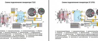
Schemes and replacement of generators for KAMAZ. 1312.3771 on G273V1
On old KAMAZ vehicles, of which there are still quite a lot, a G273 generator was installed, later a more powerful G273 V1 generator was installed, but the circuit remained the same and you can safely install a G273V1 on an old vehicle.
The same generators were installed at MAZ
The next generation of machines was equipped with a more advanced generator 1312.3771 and its analogues. If you put it in place of the G273V1 generator, then it will also work.
Let's look into the nuances.
Generator G273V1 28V, 45A. Inherited the circuit and design of the G273 generator. The battery and generator are connected through several points, which reduces the reliability of the connection, but you have to put up with it. All generators of this generation are equipped with a voltage regulator Y120 and its modifications.
The voltage regulator YA120M1 is designed according to a circuit with two inputs. One input is for excitation current, the second is for turning on the regulator. The meaning of the separated inputs is to allow the excitation current to pass directly from inside the generator, and not to conduct it along a long path through Vp and ST - (the instrument and starter switch is the same as the ignition switch).
Manufacturers, when developing a generator, wisely decided to use for this generator, which had been on the assembly line for a long time, a rotor from 14 Volt generators (rotor resistance 4.5 Ohms). In order for such a rotor to operate in a 28-volt generator, a reduced voltage is supplied to the excitation winding; for this, the excitation winding is powered not from linear voltage, but from phase voltage, which, as is known, is 1.73 times less than linear. The phase voltage is removed from the midpoint of the generator winding. Thus, the excitation current is closed from the midpoint of the star, through the excitation winding and through the rectifier (diode bridge)
Not available:
| № | Part code | Name | Part Information |
| 70-114 | Bearing | Not available | |
| G272-3701051 | Generator drive pulley | Quantity for 236 M 2) 238 M 3) 238 AM 4) 238 GM 5) 238 IM 6) 238 ND 7) 238 N 238 L 9) 238 PM 10) 238 FM 1 Model G272 Group Electrical equipment Subgroup Generator Serial number of the part 051 | Not available |
| G250A-3701055 | Fan | Quantity for 236 M 2) 238 M 3) 238 AM 4) 238 GM 5) 238 IM 6) 238 ND 7) 238 N 238 L 9) 238 PM 10) 238 FM 1 Model G250A Group Electrical equipment Subgroup Generator Serial number of the part 055 | Not available |
| G250-3701054 | Sleeve | Quantity for 236 M 2) 238 M 3) 238 AM 4) 238 GM 5) 238 IM 6) 238 ND 7) 238 N 238 L 9) 238 PM 10) 238 FM 1 Model G250 Group Electrical equipment Subgroup Generator Serial number of the part 054 | Not available |
| G273-3701400 | Cover assembly | Quantity per 236 M 2) 238 M 3) 238 AM 4) 238 GM 5) 238 IM 6) 238 ND 7) 238 N 238 L 9) 238 PM 10) 238 FM 1 Model G273 Group Electrical equipment Subgroup Generator Serial number of the part 400 | Not available |
| 6-180603K1S9 | Single row radial ball bearing with double-sided seal 20x52x18 | Quantity per 236 M 2) 238 M 3) 238 AM 4) 238 GM 5) 238 IM 6) 238 ND 7) 238 N 238 L 9) 238 PM 10) 238 FM 1 Burnished coating | Not available |
| G250A1-3701404 | Oil seal holder | Quantity per 236 M 2) 238 M 3) 238 AM 4) 238 GM 5) 238 IM 6) 238 ND 7) 238 N 238 L 9) 238 PM 10) 238 FM 1 Model G250A1 Group Electrical equipment Subgroup Generator Serial number of the part 404 | Not available |
| X-4001-01 | Spring washer | Quantity per 236 M 2) 238 M 3) 238 AM 4) 238 GM 5) 238 IM 6) 238 ND 7) 238 N 238 L 9) 238 PM 10) 238 FM 11 | Not available |
| NO-0603-10 | Screw | Quantity per 236 M 2) 238 M 3) 238 AM 4) 238 GM 5) 238 IM 6) 238 ND 7) 238 N 238 L 9) 238 PM 10) 238 FM 4 | Not available |
| G21-3701005 | Rotor cup | Quantity per 236 M 2) 238 M 3) 238 AM 4) 238 GM 5) 238 IM 6) 238 ND 7) 238 N 238 L 9) 238 PM 10) 238 FM 1 Model G21 Group Electrical equipment Subgroup Generator Serial number of the part 005 | Not available |
| G266-3701020-B | Brush | Quantity for 236 M 2) 238 M 3) 238 AM 4) 238 GM 5) 238 IM 6) 238 ND 7) 238 N 238 L 9) 238 PM 10) 238 FM 1 Model G266 Group Electrical equipment Subgroup Generator Serial number of the part 020 Additionally Interchangeable with a part released earlier under the same number | Not available |
| X-1012-01 | Spring washer | Quantity per 236 M 2) 238 M 3) 238 AM 4) 238 GM 5) 238 IM 6) 238 ND 7) 238 N 238 L 9) 238 PM 10) 238 FM 6 | Not available |
| NO-0424 | Screw | Quantity per 236 M 2) 238 M 3) 238 AM 4) 238 GM 5) 238 IM 6) 238 ND 7) 238 N 238 L 9) 238 PM 10) 238 FM 4 | Not available |
| G273-3701010 | Brush holder | Quantity per 236 M 2) 238 M 3) 238 AM 4) 238 GM 5) 238 IM 6) 238 ND 7) 238 N 238 L 9) 238 PM 10) 238 FM 1 Model G273 Group Electrical equipment Subgroup Generator Serial number of the part 010 | Not available |
| G273-3701030 | Brush | Quantity per 236 M 2) 238 M 3) 238 AM 4) 238 GM 5) 238 IM 6) 238 ND 7) 238 N 238 L 9) 238 PM 10) 238 FM 1 Model G273 Group Electrical equipment Subgroup Generator Serial number of the part 030 | Not available |
| G250A1-3701319 | Insulating sleeve | Quantity per 236 M 2) 238 M 3) 238 AM 4) 238 GM 5) 238 IM 6) 238 ND 7) 238 N 238 L 9) 238 PM 10) 238 FM 1 Model G250A1 Group Electrical equipment Subgroup Generator Serial number of the part 319 | Not available |
| X-1482 | Spring washer | Quantity per 236 M 2) 238 M 3) 238 AM 4) 238 GM 5) 238 IM 6) 238 ND 7) 238 N 238 L 9) 238 PM 10) 238 FM 2 | Not available |
| 8Х-1533М | screw | Quantity per 236 M 2) 238 M 3) 238 AM 4) 238 GM 5) 238 IM 6) 238 ND 7) 238 N 238 L 9) 238 PM 10) 238 FM 2 | Not available |
| NO-0414 | Screw | Quantity per 236 M 2) 238 M 3) 238 AM 4) 238 GM 5) 238 IM 6) 238 ND 7) 238 N 238 L 9) 238 PM 10) 238 FM 4 | Not available |
| MX-0276 | Washer | Quantity per 236 M 2) 238 M 3) 238 AM 4) 238 GM 5) 238 IM 6) 238 ND 7) 238 N 238 L 9) 238 PM 10) 238 FM 2 | Not available |
| DS1-3701107 | Screw | Quantity for 236 M 2) 238 M 3) 238 AM 4) 238 GM 5) 238 IM 6) 238 ND 7) 238 N 238 L 9) 238 PM 10) 238 FM 4 Model DS1 Group Electrical equipment Subgroup Generator Serial number of the part 107 | Not available |
| G266-3701060-13 | Lid | Quantity for 236 M 2) 238 M 3) 238 AM 4) 238 GM 5) 238 IM 6) 238 ND 7) 238 N 238 L 9) 238 PM 10) 238 FM 1 Model G266 Group Electrical equipment Subgroup Generator Serial number of the part 060 Additionally Not interchangeable with a part previously released under the same number | Not available |
| G273-3701300 | Lid | Quantity per 236 M 2) 238 M 3) 238 AM 4) 238 GM 5) 238 IM 6) 238 ND 7) 238 N 238 L 9) 238 PM 10) 238 FM 1 Model G273 Group Electrical equipment Subgroup Generator Serial number of the part 300 | Not available |
| 180502K1S9 | Single row radial ball bearing with double-sided seal | Quantity per 236 M 2) 238 M 3) 238 AM 4) 238 GM 5) 238 IM 6) 238 ND 7) 238 N 238 L 9) 238 PM 10) 238 FM 1 Burnished coating | Not available |
| G250A1-3701353 | Insulating sleeve | Quantity per 236 M 2) 238 M 3) 238 AM 4) 238 GM 5) 238 IM 6) 238 ND 7) 238 N 238 L 9) 238 PM 10) 238 FM 1 Model G250A1 Group Electrical equipment Subgroup Generator Serial number of the part 353 | Not available |
| BPPV-45-02 | Rectifier block | Quantity per 236 M 2) 238 M 3) 238 AM 4) 238 GM 5) 238 IM 6) 238 ND 7) 238 N 238 L 9) 238 PM 10) 238 FM 1 | Not available |
| M11-90118 | screw | Quantity per 236 M 2) 238 M 3) 238 AM 4) 238 GM 5) 238 IM 6) 238 ND 7) 238 N 238 L 9) 238 PM 10) 238 FM 3 | Not available |
| 8Х-1497А | Washer | Quantity per 236 M 2) 238 M 3) 238 AM 4) 238 GM 5) 238 IM 6) 238 ND 7) 238 N 238 L 9) 238 PM 10) 238 FM 1 | Not available |
| MX-0097 | Screw | Quantity per 236 M 2) 238 M 3) 238 AM 4) 238 GM 5) 238 IM 6) 238 ND 7) 238 N 238 L 9) 238 PM 10) 238 FM 1 | Not available |
| NO-1011 | Washer | Quantity per 236 M 2) 238 M 3) 238 AM 4) 238 GM 5) 238 IM 6) 238 ND 7) 238 N 238 L 9) 238 PM 10) 238 FM 2 | Not available |
| NO-1801-01 | Insulating washer | Quantity per 236 M 2) 238 M 3) 238 AM 4) 238 GM 5) 238 IM 6) 238 ND 7) 238 N 238 L 9) 238 PM 10) 238 FM 2 | Not available |
| G250A1-3701352 | Contact bolt | Quantity per 236 M 2) 238 M 3) 238 AM 4) 238 GM 5) 238 IM 6) 238 ND 7) 238 N 238 L 9) 238 PM 10) 238 FM 1 Model G250A1 Group Electrical equipment Subgroup Generator Serial number of the part 352 | Not available |
| G273-3701100 | Stator | Quantity per 236 M 2) 238 M 3) 238 AM 4) 238 GM 5) 238 IM 6) 238 ND 7) 238 N 238 L 9) 238 PM 10) 238 FM 1 Model G273 Group Electrical equipment Subgroup Generator Serial number of the part 100 | Not available |
| G265-3701200 | Rotor | Quantity per 236 M 2) 238 M 3) 238 AM 4) 238 GM 5) 238 IM 6) 238 ND 7) 238 N 238 L 9) 238 PM 10) 238 FM 1 Model G265 Group Electrical equipment Subgroup Generator Serial number of the part 200 | Not available |
| NO-7501 | Key | Quantity per 236 M 2) 238 M 3) 238 AM 4) 238 GM 5) 238 IM 6) 238 ND 7) 238 N 238 L 9) 238 PM 10) 238 FM 1 | Not available |
| МХ-0235-01 | screw | Quantity per 236 M 2) 238 M 3) 238 AM 4) 238 GM 5) 238 IM 6) 238 ND 7) 238 N 238 L 9) 238 PM 10) 238 FM 1 | Not available |
| МХ-0234-01 | Washer | Quantity per 236 M 2) 238 M 3) 238 AM 4) 238 GM 5) 238 IM 6) 238 ND 7) 238 N 238 L 9) 238 PM 10) 238 FM 1 | Not available |
| NO-1002 | Washer | Quantity per 236 M 2) 238 M 3) 238 AM 4) 238 GM 5) 238 IM 6) 238 ND 7) 238 N 238 L 9) 238 PM 10) 238 FM 1 | Not available |
Glass cleaning and auxiliary heater
The windshield is cleaned by brushes driven by an electric motor.
It has two rotor speeds. The wiper motor is controlled by a combination switch. The windshield wiper system includes an electric washer motor.
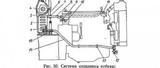
To maintain the required temperature in the cabin, KamAZ 431185 is equipped with an autonomous heater. Air circulation through the heating radiator is carried out using an electric fan.
From the above it follows that the KamAZ 43118 color wiring diagram is necessary for performing maintenance and repair of electrical equipment. The machine's wiring consists of several subsystems. The wiring is protected by fuses.
Inlet and outlet devices
The communication between the generator and the machine occurs via a network. The outer part of the device is equipped with inlet and outlet connections, the markings of which read:
- “+” — connection point with the positive terminal;
- “-” - connection point with the negative terminal, or the machine body;
- “V” / “W” - connection point with the trigger mechanism and other devices;
- “W” / “~” - connection for turning on the tachometer (43101) and the disconnector blocking the starter;
- “+D” / “D” - connection of the performance monitoring lamp.
It is necessary that the connection diagram for the KamAZ 5511 generator, etc., be followed, otherwise a breakdown is possible.
Connection diagram
DIY IT installation:
- We fix the GU on the support brackets, put on a pin and a spring washer.
- Place the belts in the grooves.
- We screw in the fastening bolts, but do not tighten them all the way.
- We move the GU body up, tighten the mounting bolts of the bar.
- We tighten the split support.
- We tighten the generator fasteners with a torque wrench with a force of 39.0 Nm.
- Check the amount of belt deflection. The range should not exceed 15 – 20 mm.
- We connect the power cables and check the connection.
- We lower the cabin.
- We put on the battery terminals.
Issues of maintenance and repair of KAMAZ generators
— Seasonal maintenance when transferring a car to summer or winter operation; — Inspection and adjustment during routine maintenance or in case of malfunction.
During seasonal maintenance, the seasonal adjustment switch is moved to position “W” (“Winter”) or “L” (“Summer”). When the cold season sets in, when the temperature remains stably below 0°C, the switch is moved to position “Z” - in this case, the regulator produces a voltage of 28.8-30.2 V.
Increasing the voltage in cold weather compensates for the voltage drop on semiconductor devices in cold weather, which guarantees normal voltage in the network. When the warm season begins, when the temperature has stably established above 0°C, the switch is moved to the “L” position - in this position the generator produces a voltage of 27-28 V.
If the generator drive belt is weakened (which is manifested by low voltage, slipping of the belt along the pulley), it is necessary to adjust its tension. To do this, loosen the bolt securing the generator to the tension bar, move the generator to ensure the desired degree of belt tension, and tighten the bolt again.
If a generator malfunctions - breaks in the windings, mechanical damage, breakdowns of the brush assembly, rectifier or regulator - it should be repaired or replaced as an assembly. Repairs are often too expensive and complicated, so in some cases it is much easier and cheaper to install a new unit. In any case, the car cannot be left without a generator, since in this case its operation is possible only until the battery is discharged.
More in this section
How to remove
Content
[ Expand ] [ Hide ]
Device Description
- Seasonal maintenance when transferring a car to summer or winter operation; - Inspection and adjustment during routine maintenance or in case of malfunction.
More in this section
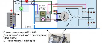
content .. 101 102 103 104 105 106 ..GENERATOR G273-V FOR KAMAZ CARS
Since 1985, KamAZ vehicles have been equipped with the G273-V generator set (Fig. 338), consisting of a three-phase synchronous generator with direct-flow ventilation and a rectifier unit and integrated voltage regulator YA120M built into the generator. The generator set is designed to operate in a single-wire electrical circuit of a vehicle with the negative terminal connected to the housing. Incorrect connection of the positive terminal of the battery to the housing leads to failure of the rectifier unit and voltage regulator.
The voltage regulator built into the generator brush holder is assembled using an integrated circuit and serves to automatically maintain the generator voltage within the specified limits necessary to ensure the charging mode of the battery and the operation of consumers.
The voltage regulator has a seasonal adjustment switch (see Fig. 338). The regulated voltage level of the generator in switch position L (summer) should be within 27... 28 V, in position 3 (winter) - 28.8... 30.2 V.
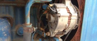
The generator is located in the upper front part of the engine and is attached with two legs to the bracket, and with the third to the tension bar, and is driven into rotation by two V-belts. The belts are tensioned by moving the generator. The generator drive gear ratio is 2.41.
The generator has the following terminals:
“ + ” - for connecting the battery and load;
“-” - for connecting to vehicle ground;
B - for connection to the VC terminal of the instrument switch and starter;
— a plug on the housing for phase output.
Technical specifications
WARNINGS!
1. Do not connect or disconnect the plug connectors and the positive terminal of the generator set while the engine is running and the batteries are connected, and do not start the engine with the positive wire disconnected from the generator.
2. Do not check the serviceability of the generator set by shorting the “+”, B, O terminals with jumpers to ground and to each other.
3. Do not connect terminal Ш of the brush holder, which is accessible through a window in the brush holder casing, with the “+” terminals of the generator, B of the brush holder. This leads to failure of the regulator.
4. Do not check the serviceability of the electrical circuit and individual wires with a megger or a lamp powered by a voltage higher than 36 V. If such a test is necessary, first disconnect the wires from the generator set.
5. To avoid failure of the rectifier unit and voltage regulator when recharging batteries from an external source, disconnect the batteries from the vehicle network.
6. When washing the car, protect the generator from water getting into it.
Maintenance
At service 2:
— clean the external surfaces of dust and dirt;
— check and, if necessary, adjust the tension of the generator drive belts. With normal belt tension, the deflection arrow should be within 15... 22 mm when pressing on the middle of the larger branch with a force of 39.2 N (4 kgf). To adjust the belt tension, loosen the nuts securing the front and rear legs of the generator and the bolt securing the generator to the tension bar. Then tilt the generator in the direction of tensioning the belts to the required value and tighten the generator fastening connections.
During service C (autumn), removing the generator from the engine:
— check the condition of the brush assembly;
— blow out the rectifier unit with compressed air;
— check that the pulley is securely fastened to the generator shaft; if it is loose, tighten it.
To check the condition of the brush-commutator
assembly, unscrew the two bolts securing the brush holder in the cover, remove the brush holder and make sure that the brushes move freely in the guides. If the brush gets stuck in the brush holder, wipe it and the walls of the guide hole with a rag moistened with gasoline. Remove the brushes, inspect and measure their height. The height of the brush must be at least 8 mm from the spring to the base of the brush. Replace brushes if necessary. Disassembly of brushes is not allowed.
Through the hole in the cover in which the brush holder is located, the slip rings are clearly visible. Inspect the condition of the slip rings and, if necessary, wipe with a rag moistened with gasoline. If burns or dirt are found after this, clean the rings with a strip of C100 glass sandpaper, pressing it against the rings through the hole in the brush holder cover and turning the generator rotor.
Grind the slip rings if burn marks cannot be removed, the rings have an uneven surface, or their wear exceeds 0.5 mm in diameter. The minimum permissible groove diameter for slip rings is 29.3 mm.
Before removing the slip ring side cover, remove the brushes along with the brush holder to avoid brush breakage.
Seasonal adjustment is carried out as follows:
- if the outside temperature is stable at 0°C and above, the PPR (seasonal adjustment switch) should be in the SUMMER position (L) - the left extreme position of the PPR contact screw, the screw is turned out;
- if the outside temperature is stable at 0°C and below, the PPR should be in the WINTER position (3) - the right extreme position of the PPR screw, the screw is screwed in.
The level of the regulated voltage of the generator in the PPR SUMMER position with a load current of 20 A, rotation speed (3500+200) min-1, ambient temperature (25+10) °C and the battery turned off should be within 27... 28 V, and in position PPR WINTER - 28.8... 30.2 V.
content .. 101 102 103 104 105 106 ..
Kamaz Generator Connection Diagram
After leaving the water, the functionality of the generator should be maintained.
In this case, the current flows to the lamp, bypassing the switch resistor, and the lamp shines at full heat. G price - from 2 rubles.
A pusher 9 is screwed into the core 8, which abuts the rod 3 of the locking device. KAMAZ disassembling the generator part 3 (checking the chocolate bar)
The core is made of electrical steel plates, insulated from each other with varnish and connected by welding along the outer surface of the package. Technical parameters The GA generator set has a rated voltage of 24 V and a power of W.
A pusher 9 is screwed into the core 8, which abuts the rod 3 of the locking device. In this case, you need to replace the block with a new one.
In this case, you need to check the fluid level in the battery banks, and also measure its charge parameter. Therefore, quite a lot of attention was paid to the issue of reliability and maintenance of components and assemblies with your own hands: Wiring KAMAZ external light alarm Electronic interlocks were introduced to prevent electrical circuits from failing.
Start-up and pre-start preparation system The start-up and pre-start preparation system of a KAMAZ vehicle includes an electric start system, an electric torch device and a pre-start heater. The rectifier block and brushes are located in the cover.
In this case, the excitation winding of the generator is connected to the power circuit through the emitter-collector junction of transistor VT2.
Correct connection of the generator "KAMAZ" Euro 2. Connect generator "KAMAZ" Euro 2.
Design and operation of the generator
Construction machines and equipment, reference book
Category:
Kamaz Ural cars
Design and operation of the generator
The generator is designed to operate in a single-wire electrical circuit of a vehicle. KamAZ 740 engines are equipped with a G288 generator operating with a voltage regulator 11.3702, or a G273-A generator set.
The G288 alternating current generator (Fig. 3.2) with electromagnetic excitation is a three-phase twelve-pole electrical machine with a built-in rectifier using six silicon diodes. The rated power of the generator is 1000 W, rated voltage 28 V, rectified current not less than 47A. The generator has the following terminals: “+”—for connecting the batteries and load, “—”—for connecting to the vehicle ground, “W”—for connecting to the “VK” terminal of the instrument switch and starter and the “I/” terminal voltage regulator.
The G273-A alternating current generator set consists of a generator, a built-in rectifier unit and an integrated voltage regulator YA-120M. Its rated voltage is 24 V, rated power is 800 W. The “+” terminal is used to connect the battery and load, and the “B” terminal is used to connect to the “VK” terminal of the instrument switch and starter.
A seasonal adjustment switch is installed on the voltage regulator, which is carried out as follows: if the outside temperature remains stable at 0 °C and above, the screw is turned to the extreme left position, but if the outside temperature is set at 0 °C and below, the screw is turned to the extreme right position .
Rice. 3.3. Generator set: 1 - pulley; 2 - ventilator; 3, 8 — covers; 4 - stator; 5 - rotor; 6 — rotor shaft; 7 - rectifier block; 9 — contact ring; 10— bearing cover; 11 — make-up resistance; 12 - voltage regulator; 13 — brush assembly
Rice. 3.4. Connection diagram of current sources: O, I, I, III - position of the instrument switch and starter key; IV— to the torch switch; V— to the instrument and starter switch; VI - to the starter retractor relay; VII - to the heater electric motors; VIII - to the reversing lights; IX - to the thermal relay of the electric torch device; 1 - generator G272; 2 - contactor; 8— push-button “ground” switch; 4—mass switch VK.860; 5 - batteries; 6— PC530 starter relay; 7 - ammeter; 8 — instrument and starter switch VK353; 9 — fuse block; 10—relay-regulator PP356; 11—relay for disconnecting the generator excitation winding; Ch - black; B—white; 3—green; F - yellow; K - red; F - purple; Bark brown; O - orange
The generator consists of a stator, rotor, covers, rectifier block, and brush assembly. The field winding is located on a shaft that rotates on two ball bearings. At one end of the shaft there is a fan and a double-strand pulley, at the other there are slip rings connected to the excitation winding along which the brushes slide. The cover contains a rectifier block and a brush holder.
The non-contact voltage regulator automatically maintains the generator voltage within limits that ensure battery charging and reliable operation of consumers.
Read more: Generator Set Maintenance
Category: — Kamaz Ural cars
Home → Directory → Articles → Forum
stroy-technics.ru