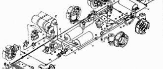
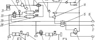
MAZ pneumatic system diagram
1 64229-3506130-10 Tube 2 008-011-19-2-3 O-ring 3 S40-3721000 Pneumatic signal 4 504V-3506197-I Tube with hose assembly 5 012-016-25-2-3 O-ring 6 6422 -3506142-10 Tube 7 64229-3506282-10 Tube 7 64229-3506282-10 Tube 8 6422-3506094 Hose to brake valve 9 54323-3506134 Tube 10 54323-3506112-20 Tube 11 5336-3506187-01 Hose 12 5549-3506187 -02 Hose 12 5549-3506187-02 Hose 13 54323-3506184 Tube 14 54323-3506194 Tube 15 54323-3506193 Tube 16 5336-3513015 Receiver 16 5336-3513015 Re receiver 17 6303-3513015-10 Receiver A40-280 17 6303-3513015- 10 Receiver A40-280 18 54323-3506158-10 Tube 19 54323-3506136 Tube 20 54323-3506240 Tube 21 11-3518010 Accelerating valve 22 54323-3506188 Tube 23 100.3 562010 Double-line valve 23 100.3562010 Double-line valve 24 54323-3506180 Tube 25 5434-3506098 Connector with hose 26 6422-3506085-01 Hose 27 100-3533010 Brake force regulator 28 54323-3506289-10 Tube 29 5336-3506085-01 Hose to rear brakes 30 54323-3506243-10 Tube 31 943.002.521.0 Trailer control valve 32 64229 -3506132-10 Tube 33 64229-3506183-10 Tube 34 54323-3506146-10 Tube assembly 35 100-3514008 Valve with lever assembly 36 64229-3506283-10 Tube 37 100-3512010 Pressure regulator assembly 38 100-3536010 Fuse anti-freeze 39 943.702.120.0 Four-circuit valve 40 11.3511010 Water separator assembly 41 961.702.005.0 Brake valve 42 100-3537110 Brake valve 43 5336-3570234 Pipe 44 5336-357023 0 Tube 45 64221-3537020-20 Tube 46 64229-3506139-10 Tube 47 64226-3570240-10 Tube 48 54323-3506248 Tube 49 64226-3570212-10 Tube 50 16.3741000 Pneumatic valve 51 5516-1115040 Tube 52 64226-3506316 Tube 5 3 64229-3506336-20 Tube 54 64229-3506337-20 Tube 55 100-3570210 Cylinder 56 100-3519210-01 Front brake chamber 57 5336-3519200 Rear brake chamber Link to this page: https://kspecmash.ru/catalog.php?typeauto=2&mark=11&model=26&group=152
MAZ model tractors are very popular among car enthusiasts due to its reliability and reasonable cost. This vehicle has been manufactured at a specialized plant in Minsk since 1988.
The car has a large cabin and ease of operation. The salon has two comfortable soft chairs. If necessary, the cabin can be tilted to the rear position thanks to the presence of a hydraulic cylinder, which is activated manually. Vehicles are distinguished by increased reliability and endurance, especially when transporting large cargo over long distances.
The MAZ brake system acts as the main component of the vehicle. If certain faults are detected in it, the driver loses confidence in his own safety. In such a case, you should not neglect repairs and seek help from a specialist as soon as possible.
In MAZ cars there are four systems simultaneously, which are quite closely intertwined. Among them it should be noted:
- Working.
- A spare system (it comes into operation after the first one breaks down).
- Parking system (if it breaks down, the vehicle will not stand in one place and parking problems will arise).
- Auxiliary (turns off the engine).
6.5. Brake systems of MAZ vehicles. Brake repair. - “IMPORTANT TO EVERYONE”
Brake repair. The parts that suffer the most wear in service brakes are the friction linings and working surfaces of the drums, as well as the bushings and journals of the expansion knuckles and the axles of the pads. The design of the brake mechanisms provides for an easily removable brake drum and the ability to visually determine the condition of the brake linings through hatches in panels 21 (see Fig. 56). To disassemble the service brake, you need to jack up the wheel, remove the tire and, unscrewing the nuts, remove the disc from the studs 19. Then you need to screw two M16 bolts into the dismantling threaded holes of the drum 29 and remove the drum by evenly screwing in the bolts. After this, you need to remove the tension springs 23, unscrew the bolt 20 and, moving the pads 28 away from the expansion knuckle 24, remove them from the axles 22. Disassembling the front wheel brake is given in section “4.4 Front axle and steering rods. Device". Friction linings must be replaced if the distance from the surface of the lining to the head of the rivets remains less than 1.0 mm.
Installation of new linings and riveting them to the blocks is carried out in a special device that ensures a tight fit of the lining to the surface of the block. The local gap between the block and the lining should not be more than 0.3 mm; the shape of the rivet, its dimensions, as well as the dimensions of the hole for the rivet in the lining are shown in Fig. 113. The riveting is done from the block side; we hide the head of the rivet and should lie on a mandrel that ensures that the head retains its shape during the riveting process. Riveting can be done in a vice using a simple tool. After riveting the linings, the pads assembled with the linings must be processed in pairs along the outer diameter to the nominal size, if the drum has not been bored to the repair size. If the drum is bored to one of the repair sizes, then the pads assembled with linings must be machined to the same repair size number (Table 13).
The processing of the pads is carried out on a lathe using the R-114 installation, which ensures the correct placement of a pair of pads. If necessary, brake drums are bored to one of the repair dimensions indicated in Table 13. Wear of the expansion knuckle journals is allowed up to a diameter of 39.75 mm, and the expansion knuckle bushings - up to 40.10 mm. If these surfaces are worn beyond the specified values, the journals are welded and machined to a nominal diameter of 40±0.075 mm, and the bushings are replaced with new ones. Wear of the support journals of the pad axles is allowed up to a diameter of 31.88 mm. The wheel brake is assembled in the reverse order of disassembly. When installing the pads, you need to lubricate the axles 22 with Litol-24 grease GOST 21150-75.
vajnovsem.ru
Device
The brake system circuit is designed on the principle of independent influence on the drive mechanisms of the wheels of the front and rear axles. The pneumatic vehicle used on MAZ vehicles consists of the following elements:
- compressor;
- compressed air tanks (receivers);
- pneumatic pipelines and control devices;
- brake mechanisms.
The vehicle can be equipped with a single or double cylinder compressor. The latter is used on tractors (road trains).
Compressed air is supplied through a pneumatic line to the receivers. Depending on the model, the vehicle can use 3 or 4 air cylinders of different capacities. Each pair of wheels (axle) has its own receiver: front and middle - 40 liters each, rear - 20 liters. The parking system is equipped with a separate 20-liter cylinder.
The design of the MAZ brake system provides for the installation of drum-type brakes.
Here, braking occurs due to friction arising from the contact of the pads located on a stationary caliper to the inner surface of the movable (rotating) drum. It is made of cast iron with a diameter of 420 mm and a working surface width of 160 mm.
The brake pads are made of steel. Friction linings made of asbestos-free material are installed on top. The gap between the pads and the surface of the drum is adjusted by a lever with a built-in automatic adjuster. The front wheel brakes are actuated by diaphragm brake chambers (BC). On the rear axles, the force on the pads is transmitted by spring energy accumulators.
Control air is supplied to the actuators by the brake valve through a four-circuit valve. This applies the brakes on all wheels simultaneously. If there is a trailer, to prevent it from hitting the tractor, a trailer brake control valve is installed, which allows the brakes to be applied slightly faster than on the tractor.
Brake system of cars Maz-5516, 5340, Maz-6430, 64229, Maz-5440, 54323, 54329
_______________________________________________________________________________________
Cars Maz-5516, 5340, Maz-6430, 64229, Maz-5440, 54323, 54329 are equipped with working, parking, spare and auxiliary brake systems, as well as devices for connecting the brake system of a semi-trailer with a two-wire pneumatic drive and outputs for powering other consumers with compressed air. air. The working brake system Maz-5516, 5340, Maz-6430, 64229, Maz-5440, 54323, 54329 affects the braking mechanisms of all wheels of the car. The drive mechanisms are pneumatic with separate braking of the front and rear wheels. Electro-pneumatic pressure modulators of the anti-lock braking system (ABS) are installed in the brake mechanism drive. The parking and spare brake systems of Maz-5516, 5340, Maz-6430, 64229, Maz-5440, 54323, 54329 vehicles act on the brake mechanisms of the middle and rear axles, which are actuated by brake chambers with spring energy accumulators (Figure 25). Control is carried out using a crane in the driver's cabin. The parking brake system also serves as a spare one. It is designed to brake the vehicle in the event of a complete or partial failure of the service brake system. When the parking brake system is activated, the control valve handle is set (by turning) to its extreme fixed position. Compressed air, compressing the power springs of energy accumulators, is released into the atmosphere and the springs activate the brake mechanisms. When turning on the spare brake system of Maz-5516, 5340, Maz-6430, 64229, Maz-5440, 54323, 54329 vehicles, the parking brake control valve handle is held in any intermediate non-fixed position. As the angle of rotation of the handle increases, the braking intensity increases due to a decrease in air pressure compressing the springs of the energy accumulators. The auxiliary brake system acts on the vehicle's transmission by creating back pressure in the exhaust system using an air-actuated throttle body. It is designed to slow down the car on long descents of mountain roads. The Maz-5516, 5340, Maz-6430, 64229, Maz-5440, 54323, 54329 vehicles are equipped with a speed limiting system consisting of cylinder 15 (Figure 27) and a proportional valve 14, as well as an anti-slip system consisting of an electro-pneumatic valve and two two-way valves. The control of these systems is electronic. Air is supplied to the fuel control cylinder through a proportional valve, which is controlled by the electronic traction control and speed limiting systems. When the tractor vehicle is braked by the working or parking (spare) systems, the semi-trailer (trailer) is simultaneously braked. Fig.25. Brake chamber of Maz-5516, 5340, Maz-6430, 64229, Maz-5440, 54323, 54329 cars with a spring energy accumulator 1.7-springs; 2 - disk. 3 - diaphragm; 4 - pusher. 5 - cylinder; 6 - piston; 8 - bolt; 9 thrust bearing; 10 - rod Brake mechanisms of cars Maz-5516, 5340, Maz-6430, 64229, Maz-5440, 54323, 54329 Brake mechanisms of cars Maz-5516, 5340, Maz-6430, 64229, Maz-5440, 54323, 54329 drum type with two internal shoes and an easily removable brake drum. There are special holes in the brake pads (opposite the tension spring hooks) to allow the spring to be removed when replacing the brake pads (linings). On cars Maz-5516, 5340, Maz-6430, 64229, Maz-5440, 54323, 54329, an adjustment lever with a built-in automatic slack adjuster is installed (Figure 26). Diaphragm brake chambers are designed to activate the brake mechanisms of the front wheels of a car when the service brake system is activated. The brake chambers of Maz-5516, 5340, Maz-6430, 64229, Maz-5440, 54323, 54329 cars with spring energy accumulators (Fig. 25) are designed to activate the brake mechanisms of the wheels of the rear and middle axles when the working, parking and spare brakes are engaged systems When the service brake system is turned on, the brake mechanisms are actuated by the rods of 10 diaphragm brake chambers, the design and principle of operation of which is practically no different from the front brake chambers. When the parking brake system is turned on, compressed air is released from the cavity under the piston 6, which, under the action of the power spring 7, moves down and moves the pusher 4, the latter, through the thrust bearing 9, acts on the diaphragm 3 and the rod 10 of the brake chamber, resulting in the car braking. When the parking brake system of the Maz-5516, 5340, Maz-6430, 64229, Maz-5440, 54323, 54329 vehicles is turned off, compressed air is supplied under the piston 6, which, together with the pusher, moves upward, compressing the spring and allowing the brake chamber rod under return to its original position by the action of return spring 1. When braking by the reserve system, air from the cylinders of the energy accumulators is partially released to the extent of the required braking efficiency of the vehicle, which corresponds to the intermediate positions of the control valve handle. Thus, the braking efficiency depends on the angle of rotation of the crane handle. Fig. 26 — Brake adjustment lever Maz-5516, 5340, Maz-6430, 64229, Maz-5440, 54323, 54329 1 — body; 2 — pusher, 3 — movable coupling half; 4 - fixed coupling half; 5 - spring; 6 - plug; 7 - shaft - worm; 8, 9, 10 — sealing rings; 11 - screw; 12 - cover; 13 — leash 14 — control ring; 15 - gear; Pneumatic brake drive of cars Maz-5516, 5340, Maz-6430, 64229, Maz-5440, 54323, 54329 The schematic diagram of the pneumatic drive of the brake system is shown in the figures below. Adjusting the service brake of Maz-5516, 5340, Maz-6430, 64229, Maz-5440, 54323, 54329 cars The initial position of the brake pedal (size 245 mm) is adjusted by bolt 6 by screwing it in or out. In this case, bolt 6 should touch the pedal guard with its thorium. The free travel of the brake pedal (3+1J mm is adjusted by rod 4 - by rotating the hexagon of the pusher 2 with the lock nut 3 released. Maintenance of the pneumatic brake drive of Maz-5516, 5340, Maz-6430, 64229, Maz-5440, 54323, 54329 vehicles . servicing the pneumatic brake drive of the Maz-5516, 5340, Maz-6430, 64229, Maz-5440, 54323, 54329 vehicles must be monitored first of all, ensure the tightness of the system as a whole and its individual elements.Particular attention should be paid to the tightness of connections of pipelines and flexible hoses and hose connection points, since this is where compressed air leaks most often occur. Places of strong air leakage are determined by ear, and places of weak leakage are determined using a soap emulsion. Air leakage from pipeline connections is eliminated by tightening or replacing individual elements of the connections. Leakage is eliminated by tightening connection nuts torque: for pipelines with a diameter of 6 mm - 9.8 - 12.3 Nm (1 - 1.25 kg/cm), 10 mm -21.6-27.5 Nm (2.2 - 2.8 kg /cm); 15 mm - 49 - 60.8 Nm (5 - 6.2 kg/cm). If after tightening the leak is not eliminated, the rubber O-rings must be replaced. To avoid breakage of connecting bosses on brake devices, the tightening torque of fittings, plugs, nuts and other fittings should not exceed 30 -50 Nm (3 - 5 kg/cm). The tightness test should be carried out at a nominal pressure in the pneumatic drive of 588 kPa (6.0 kgf/cm2), with compressed air consumers turned on and the compressor not working. The pressure drop from the nominal pressure in air cylinders should not exceed 30 kPa (0.3 kgf/cm2) for 30 minutes, with the drive controls in a free position and for 15 minutes. when turned on. Care and maintenance of chambers with spring energy accumulators of Maz-5516, 5340, Maz-6430, 64229, Maz-5440, 54323, 54329 cars consists of periodic inspection, cleaning of dirt, checking the tightness and operation of the brake chambers, tightening the nuts attaching to the bracket. The tightening torque should be 177 - 196 Nm (18 - 20 kg/cm) for spring energy accumulators and 108 - 137 Nm (10.8 - 13.7 kg/cm) for front brake chambers. Check the spring-pneumatic brake chambers for leaks when there is compressed air in the emergency or parking brake drive circuit and in the rear bogie brake drive circuit. To check the emergency or parking brake of Maz-5516, 5340, Maz-6430, 64229, Maz-5440, 54323, 54329 vehicles for leaks, release the parking brake of the vehicle. This will fill the cylinders with compressed air. Then determine the air leak. The presence of an air leak indicates damage to the cylinder sealing elements. In this case, replace the cylinders with brake chambers.
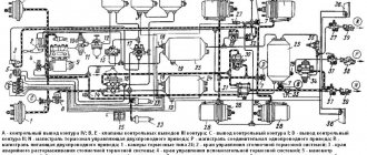
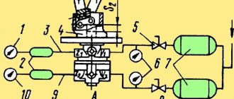
Fig.27. Diagram of the pneumatic brake drive of a Maz 6x4 car with spring suspension (Yamz engine).
Fig.28. Diagram of the pneumatic brake drive of a Maz 4×2 car with spring suspension (YMZ engine).
Fig.29. Diagram of the pneumatic brake drive of a Maz 6x4 car with air suspension (YaMZ engine).
Fig.30. Diagram of the pneumatic brake drive of a Maz 4×2 car with air suspension (YMZ engine). Fig.31. Diagram of the pneumatic brake drive of a Maz car with a MAN or Deutz engine. Figure 27-31. Diagram of the pneumatic drive of the brakes of the Maz-5516, 5340, Maz-6430, 64229, Maz-5440, 54323, 54329 cars 1 - compressor: 2 - pressure regulator with adsorber; 3 — regeneration receiver: 4 — four-circuit valve; 5 - towing valve; 6 - consumer receiver; 7 — front circuit receiver; 8 — rear circuit receiver; 9 — parking circuit receiver; 10 — engine brake button; 11 — EPK anti-theft system and engine brake; 12 — pneumatic cylinder of the engine brake flap; 11 — fuel supply limiting pneumatic cylinder; 14 — speed limit valve; 15 — speed limiting pneumatic cylinder; 16 — brake valve; 17 — front circuit ABS modulator; 18 — front brake chamber: 19 — rear circuit ABS modulator; 20 — brake chamber with spring energy accumulator; 21 — brake force regulator with built-in accelerator valve; 22 — two-line valve; 23 — PBS valve; 24 — trailer brake control valve; 25 — connecting control head (yellow cover); 26 — connecting supply head (red cover); 27 — parking brake valve; 28 — check valve; 29 — accelerator valve of the parking brake system; 30 — control valve; 31 — sensor block; 32 — condensate drain valve; 33 — sensor for turning on the engine brake; 34 — accelerator valve of the service brake system; 35 — cylinder of the engine energy saving system; 36 - brake force regulator without built-in accelerator valve. The pneumatic drive of the brakes of the Maz-5516, 5340, Maz-6430, 64229, Maz-5440, 54323, 54329 cars is equipped with pneumatic devices that do not require special maintenance and adjustment. The tightness of the connection largely depends on the correct centering of the piston of the connecting head of the tractor in the sealing collar of the connecting head of the trailer (semi-trailer). Check the tightness of the coupling heads when coupling vehicles with a semi-trailer sequentially in the braked and unlocked positions. The pneumatic brake drive of Maz-5516, 5340, Maz-6430, 64229, Maz-5440, 54323, 54329 vehicles uses a pressure regulator combined with an adsorption compressed air dryer. The compressed air dryer filter element (cartridge) is replaced as necessary when the presence of condensate is detected in the pneumatic system receivers. Depending on the operating conditions and technical condition of the pneumatic drive devices, the replacement frequency can range from one to two years. Therefore, you should periodically check for condensation in the brake system receivers. When draining condensate from cylinders, to avoid splashing your hands, you must use a hook made of wire. Replace the filter element (cartridge) of the compressed air dryer Maz-5516, 5340, Maz-6430, 64229, Maz-5440, 54323, 54329 in the following order: - clean the surface of the dryer from dirt; — loosen the threaded connection of the discharge pipeline from the compressor (inlet 1) and bleed air from it; — unscrew the cartridge by rotating counterclockwise; — wipe the inside of the dryer body, preventing dirt from getting into the check valve; — install a new cartridge, for the Vabko dryer No. 432410 020 2, for the KNORR dryer No. II 17793 or 1140100 F. (for the BelOMO dryer - repair kit 8673.00.00.000 - 01 or cartridge Vabko or KNORR), lightly lubricating the sealing gasket with oil; — tighten the cartridge by hand (torque no more than 15 Nm). Caring for Maz-5516, 5340, Maz-6430, 64229, Maz-5440, 54323, 54329 wheel brakes involves periodically replacing the brake linings as they wear out. The degree of wear of the pads can be monitored through inspection holes in the shields. There is a wear limit line at the ends of the linings, which allows you to visually determine the need to replace them. If the linings were replaced by removing the wheel hub, then after installing it, you must press the end of the ABS wheel sensor with a screwdriver or other similar object and bring it into contact with the inductor (ring gear), and then turn the hub 2 - 3 turns. The gaps between the linings and the drum are regulated by an automatic adjustment lever, the operation of which largely depends on its correct installation. The stroke of the brake chamber rods should be within 38 - 44 mm (when applying maximum pressure). After replacing the linings, as well as when replacing the adjusting lever or brake chamber, it is necessary to adjust the stroke of the brake chamber rods. Adjusting the stroke of the brake chamber rods Maz-5516, 5340, Maz-6430, 64229, Maz-5440, 54323, 54329: - install the adjusting lever on the expansion cam shaft like this. so that the distance from the brake chamber fork to the lever is 20 - 80 mm. In this case, the lever should be positioned with the plug forward along the brake chamber rod when braking, and the hexagonal end of the shaft - with the worm facing the brake chamber (when replacing on the rear axle, brake chambers with spring energy accumulators must be released); — by rotating the hexagonal end of the worm shaft counterclockwise, you should feel the clicks of the reverse clutch, align the holes of the chamber rod fork and the lever and connect the lever to the fork with your finger. In this case, the expansion cam shaft must remain in its original position under the action of the tension spring of the pads; — turn the lever lever all the way (in the direction of rotation of the lever when braking), and secure the lock in this position; — adjust the stroke of the brake chamber rod by successively pressing the brake pedal all the way at a compressed air pressure in the system of at least 600 kPa (6 kgf/cm2), until a constant value of the rod stroke is established within the range of 38-44 mm. Caring for the adjusting lever (Figure 26) consists of periodically lubricating it through a press-lubricator 18 until the grease comes out of the safety valve 19. When removing the brake drum Maz-5516, 5340, Maz-6430, 64229, Maz-5440, 54323, 54329 for To increase the gap between the brake pads and the drum, it is possible to unscrew the plug with a K1/8″ thread from the lever body, use a thin screwdriver to disengage the movable half-coupling from the ratchet connection and turn the worm axis clockwise by the hexagon, and then install the plug in place. After installing the brake drum, it is necessary to adjust the stroke of the brake chamber rod as indicated above. During operation, periodically monitor the operation of the levers by measuring the stroke of the chamber rod. The difference in rod strokes should not exceed 5 mm. If an increased stroke is detected, check the correct installation of the lever or find out the cause of the malfunction and eliminate it, for which purpose disassemble the lever and clean and rinse the parts. Disassembling the brake drum lever Maz-5516, 5340, Maz-6430, 64229, Maz-5440, 54323, 54329 is carried out in the following order: - unscrew plug 6, having previously unlocked it; — remove spring 5 with coupling half 3; — remove cover 12 with driver 13 and control ring 14 assembled and gasket 17, pusher 2; — remove worm 7 with half-coupling 4 assembled; — remove gear 15.
_______________________________________________________________________________________
_______________________________________________________________________________________
- 970 Elite
- TLB 860
- Cat 422
- Cat 428
- Cat 434
- Cat 444
- 3 CX Super
- 4 CX
- 5 CX
- WZ30-25
- XT860/XT870
_______________________________________________________________________________________
- WB 97S
- WB 93R
- Hyundai H940S
- B110
- B115
- Hidromek HMK 102B
- Hidromek HMK 62SS
_______________________________________________________________________________________
- Mobile cranes
- Cranes manipulators
- Motor graders DZ-122,143
- Excavator EK-14
- Kamaz truck repair
- MAZ truck repair
- TL 65
- TL 120
- TL 310
- Cat 914
- Cat 924
- Caterpillar 950
- Caterpillar 966
_______________________________________________________________________________________
- LW500F
- ZL30G
- ZL50G
- LW321F
- XGMA XG932
- XGMA XG955
- Design of Terex, Komatsu, Cat loaders
- ZW250
- ZW310
- ZW220
- ZW180
- W130
- W170
- W190
- W270
- L34
- Adjusting the D-180 engine
- Transmission T-170
- Assembly of gearboxes T-170, T-130
- Adjusting the T-170 clutch
- Hydraulic and mounted systems T-170
- Main gear T-170, T-130
- Diesel injection pump D-160
- Servo mechanism of clutch T-130, T-170
- Onboard clutches T-130
- Final drive of the T-130 tractor
- Rotation control mechanism T-130
- Hydromechanical transmission TO-18/TO-18B
- Hydraulic system GMP TO-18/TO-18B Amkodor
- Hydraulic system TO-18
- Hydraulic system components TO-18/TO-18B Amkodor
_______________________________________________________________________________________
- Design of rack and pinion hydraulic cylinders
- Types of positive displacement hydraulic pumps
- Rotary screw pumps - Design and operating principle
- Characteristics and design of gear pumps
- Pump control diagram in a closed hydraulic system
- Hydraulic distributor device with proportional control
- Hydraulic systems of special equipment - operation and maintenance
- Application of hydrostatic transmissions for special equipment
- Application of cartridge electrically controlled valves
- Design and diagrams of cartridge plug-in hydraulic valves
- Characteristics of Screw-in Hydraulic Cartridge Valves
- Sequence valve and pressure reducing valve operating diagrams
- Variable displacement hydraulic pump regulator
- Load Sending System for Variable Pumps
- Hydraulic distributors - Control systems
- Control diagrams for working hydraulic units of special equipment
Advantages of the vehicle
MAZ trucks are quite often designated as superautos. This name is quite justified, since the car is as advanced as possible. The elements and mechanisms of the car are made in a unique exclusive design. The MAZ brand vehicle is fully equipped with a variety of modern devices. It is for this reason that cars are very popular and are used in a wide variety of areas of the construction and industrial sectors.
A modern truck tractor is characterized by a large number of undeniable advantages. Among the most important positive aspects are:
- A true hard worker who is ready to work without any failure at full load;
- Optimal performance and load capacity, the truck does not let the driver down on long trips;
- High reliability indicators.
Thanks to these positive qualities, the truck was in demand during the Soviet Union and is popular today. The vehicle's middle axle is a pass-through structure that is installed to reduce the overall load on the main rear axle. One of the important details is the presence of a center differential, the purpose of which is to effectively distribute the total torque between the main axles. The design is installed on the rear axle and only on cars that are characterized as three-axle. At the same time, competent, uninterrupted driving and operation are ensured through timely technical inspections.
The cabin of the MAZ truck deserves special attention. Drivers appreciate it for its high levels of comfort and practicality. In terms of external characteristics, the truck is quite attractive. The latest models are equipped with uniquely shaped headlights, the design of the cabin itself, and also the radiator. In the new models, the shape of the windshield has been slightly changed; if previously it was split, now it has a panoramic one. The shock-proof bumper was replaced with a more attractive aggregate one, on which the headlights are installed. The entire interior of the cabin has been slightly improved, it has unique levers and the most comfortable steering wheel.
Malfunctions
When operating a vehicle, the following breakdowns may occur:
- low braking efficiency;
- uneven braking of the wheels of the right and left sides;
- jamming of service or parking brakes (brake jam);
- increased travel of the parking brake handle.
An increase in braking distance can occur due to a large gap between the pads and the brake drum (TB), due to wear of the pads or insufficient output of the rod at low pressure in the pneumatic system. If such a malfunction appears after repairs associated with replacing the pads, then there is a high probability of oiling of the friction material or the inner surface of the brake pad.
In most cases, a car skidding during braking occurs due to a large difference in the strokes of the brake rods installed on one axis or the shaft getting stuck in the expansion cam bushings in the brake pad block.
Slow release most often occurs due to a broken or stuck return spring in the brake cylinder. The cause of such a defect may also be incorrect adjustment of the brake pedal. Therefore, the brake valve lever does not reach the stop. Due to the breakdown of the brake pad tension springs, spontaneous braking may occur, and a characteristic knocking sound in the wheel will be heard when driving.
When driving a truck with a trailer, there may be a delay in the latter's braking. This is due to incorrect installation of the adjusting ring in the brake valve. The same failure is typical for a stuck piston in the trailer air distributor.
It must be remembered that a breakdown in the steering will only lead to a loss of control of the car, and a vehicle failure will lead to the impossibility of stopping it, which will inevitably end in an accident.
How MAZ brake mechanisms work
Brake mechanisms are drum-type with two internal shoes and an easily removable brake drum.
On vehicles equipped with ABS, special holes are made in the brake shoes of the rear axle (opposite the tension spring hooks) to ensure the removal or replacement of brake shoes without disassembling the wheel drive.
At the end of the expansion cam shaft there is a worm-type adjusting lever (Fig. 1) connected to the brake chamber rod.
By turning worm 3 by the hexagonal head of the axle with a wrench, you can turn the expansion fist and, consequently, spread the brake pads, thereby reducing the gap between them and the drum.
To rotate the axis, plate 7 must be released and moved upward.
On vehicles, an adjustment lever with a built-in automatic regulator can be installed (Fig. 2).
To prevent lubricant from entering the brake mechanisms, rubber O-rings are installed in the brackets of the front and rear brake expansion knuckles.
The brake chambers are diaphragm, designed to activate the brake mechanisms of the front wheels of the car when the service brake system is turned on.
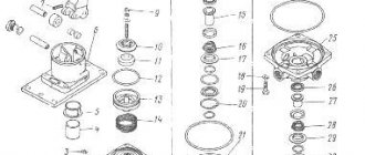
Brake chambers with spring energy accumulators (Fig. 3) are designed to activate the brake mechanisms of the wheels of the rear and middle axles when the service, parking and spare brake systems are engaged.
When the service brake system is turned on, the brake mechanisms are actuated by the rods of 10 diaphragm brake chambers, the design and principle of operation of which is practically no different from the front brake chambers (inlet 11).
When the parking brake system is turned on, compressed air is released from the cavity under the piston 6, which, under the action of the power spring 7, moves down and moves the pusher 4, the latter, through the thrust bearing 9, acts on the diaphragm 3 and the rod 10 of the brake chamber, resulting in the car braking.
When the parking brake system is turned off, compressed air is supplied under the piston 6 through the inlet 12, which, together with the pusher, moves upward, compressing the spring and allowing the brake chamber rod to return to its original position under the action of the return spring 1.
When braking by the reserve system, air from the cylinders of the energy accumulators is partially released to the extent of the required braking efficiency of the vehicle, which corresponds to the intermediate positions of the control valve handle. Thus, the braking efficiency depends on the angle of rotation of the crane handle.
It is possible to install diaphragm brake chambers with a spring energy accumulator and a quick-release device on the vehicle (see Fig. 4).
The quick-release device (QRU) is a spring-loaded fixing sleeve 9, which provides connection of the diaphragm 5 with the rod 4 of the energy accumulator through balls 8.
The chamber is released as follows: remove the cover, insert the pusher 12 (located in the spare parts box) until it stops into the fixing sleeve 9 and press or lightly hit with a hammer. In this case, the sleeve 9 moves, the balls 8 come out of the groove on the rod
4, the diaphragm 5, under the influence of the spring 11, moves all the way into the body, the spring 1 moves the rod 4, releasing the wheel brake mechanism.
When compressed air is supplied to cavity “A”, the balls 8 fall into the groove of the rod 4 and are fixed by the sleeve 9, while the energy accumulator is blocked.
Self-disassembly of spring energy accumulators is strictly prohibited!
The brake mechanism of the main parking brake system of MAZ-631705, 631708, 642505, 642508, 533605 vehicles is drum (Fig. 5), double servo shoe with lever release of the shoes and a gap adjustment mechanism.
It is attached to the transfer case housing, the brake drum is attached to the transfer case output shaft flange.
The action of the brake is as follows. When braking, the force from the drive cable is transmitted to the drive lever 9, which, through the intermediate lever 17 and the link 8, acts on the shoe lever 7.
When the drum rotates counterclockwise, the driving force from the shoe lever is transmitted through rod 3 to the left shoe 22 and presses it against the brake drum.
In this case, the block, due to friction, is captured by the drum and moves in the direction of rotation, pressing through the adjusting device on the right block 16, and presses it against the drum.
When the brake drum rotates clockwise, the shoe lever 7, resting on the rod 3, transmits the drive force to the right shoe 16 and presses it against the drum.
Due to friction, the block is captured by the drum and is shifted in the direction of rotation, pressing through the adjusting device on the left block 22, and presses it against the drum.
The drive diagram is shown in Fig. 6, the design of the control lever is shown in Fig. 7.
The mechanism of the auxiliary brake system (Fig. throttle type with flaps installed in the engine exhaust pipe in front of the muffler.
The mechanism consists of a body and dampers 2, mounted on an axis 3.
A rotary lever 4, connected to the rod of the drive pneumatic cylinder, is also attached to the damper axis.
Lever 4 and the dampers 2 associated with it have two fixed positions.
When the auxiliary brake is turned off, the damper is installed along the exhaust gas flow, and when turned on, it is perpendicular to the gas flow, creating back pressure at the outlet.
Cost of work
| Price | |
| Adjusting the brakes | 1,100 rub. |
Sign up for the service
The prices indicated on the website are not final and may change either up or down.
Currently there are 2 special offers and promotions
Original spare parts for MAZ trucks from a warehouse in Moscow
- Truck service center "ST Service"
- Technical - Your reliable assistant if your truck requires repairs or maintenance during the warranty and post-warranty period of operation.
- 9 years on the market
- Convenient location
- in the north of Moscow Read more
Possibility of your presence next to the car during maintenance or repairs
- Comfortable waiting room with air conditioning and coffee machine
- and free wi-fi
Equipment and workshops
Stand TS 1500 CAORLE for turning brake drums and brake discs.
Stand for testing and adjusting mechanical injectors
Stand for testing and adjusting high pressure fuel pumps (HPF)
9 posts equipped for maintenance
Bosch EPS205 - test bench for common rail injectors
CR-NeXT - complex for repair and adjustment of injectors
MP-250 SASH - machine for rebuilding injector valve
Certificates for performance of service work by Technical
The following trucks are serviced at the ST Service truck service center:
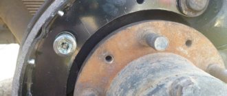
How to remove a brake drum
During vehicle operation, both the brake pad linings and the inner surface of the drum wear out. As a result, braking efficiency is lost. In this case, it is necessary to dismantle the drum and replace the pads. The dismantling work is not difficult, but it will require some physical effort, because... the parts are heavy.
See » Technical characteristics and design of the MAZ-241 passenger bus
To remove the brake drum, do the following:
- install the machine on a flat surface and secure it against possible movement;
- jack up the wheel;
- unscrew the nuts and remove it;
- screw 3 M10 bolts into the holes on the drum cover and press it out;
- remove the part from the hub.
It must be remembered that the TB is made of cast iron, so you need to use a hammer to remove it with great care.
Replacing linings
Brake pads consist of two parts: a metal body and a friction lining. Previously, about 40 years ago, the linings were made of asbestos-containing material, which was installed on a metal part using rivets. The service life of such parts was small and amounted to 40-50 thousand km. Today, new friction materials are used that can last 180-200 thousand km without replacement. Therefore, there is no point in replacing brake linings, and the pads are replaced as a set.
After removing the drum to dismantle the elements, you must perform the following steps:
- remove the spring that tightens the pads;
- dismantle the cups with springs that press the parts to the protective casing;
- remove the pads from their seats.
If you decide to replace only the friction linings, then in addition to the listed actions you must perform the following:
- dismantling the remaining friction material;
- cleaning the surface of the part;
- installation of new linings;
- processing on a lathe to the required size.
The installed material must have a thickness of at least 7 mm, with a margin of 3.5 mm to the rivet head. The gap between the friction material and the pad body is allowed no more than 0.1 mm. Such work can be performed without special devices using a bench vice in compliance with the required dimensions and tolerances.
Summing up
Many people are motivated to purchase this car by the numerous positive reviews about the truck from the owners. What deserves the greatest admiration is its attractive appearance, small dimensions, carrying capacity; it is very comfortable and solid to sit behind the wheel of this car. Also attractive is the optimal combination of price and quality of the truck. Almost everyone notes the ideal handling of MAZs; they get real pleasure from the work process on this machine. Standard work can be carried out with an optimal level of control and comfort at the same time.
Maintenance
With proper operation, the MAZ 5440 air dehumidifier will last for several years. For normal operation of the device, monitor the pneumatic drive. Monitor the tightness and presence of condensate in the receivers. To prevent the device from freezing in winter, turn off the engine after turning on the pressure regulator.
The timing of replacing the MAZ 4370 air dryer depends on operating conditions. Over time, the adsorbent loses its ability to absorb moisture. Therefore, regeneration is necessary. Backflush the dryer from the receiver.
If you follow the deadlines for replacing the MAZ 4370 air dryer and cartridge, the device will reliably protect the system from breakdowns and destruction. If the valves break, you will have to install a new device.
The muffler can be replaced separately.
It is recommended to replace the cartridge once a year. When installing a new spare part, remove the old gasket. The new seal is lubricated with oil. Repair work is carried out with the air supply turned off.
You can buy the necessary spare parts and find out the price of a MAZ air dryer on our website.
MAZ brakes - diagram, parking brake, manual - TD Spetsmash
Of course, the MAZ electrical circuit is one of the most difficult for ordinary drivers who do not have a special electrical engineering education to understand its principles. At the same time, Minsk-made cars have plenty of systems that are only slightly inferior in complexity to electrical devices. Such complex systems include the MAZ brake system. Moreover, its main difficulty is that it consists of several subsystems at once, different in structure, specific purpose (in some cases, subsystems perform the functions of their “brothers”) and in the principles of interaction with other subsystems. The standard MAZ brake circuit includes the following subgroups:
- working; - auxiliary; - spare; - parking.
Using the latter as an example, we will tell you what needs to be done to prevent problems in the system and prevent breakdowns...
The MAZ handbrake and its drive do not require special care, but some rules should be remembered:
• be sure to periodically inspect the drive cables and hinge joints for signs of wear, and if they appear, replace them immediately; • do not allow fastenings to loosen or connections to become dirty; • when lubrication, strictly adhere to the lubrication chart recommended by the manufacturer, but do not forget to make adjustments to it in case of deviations in operating conditions; • before each departure, additionally make sure that the MAZ parking brake functions without failure and is capable of holding the vehicle within the specified limits.
Such limits are regulated by the manufacturer; for example, for the 5335 family of Minsk tractors, there is a standard according to which the handbrake must hold a fully loaded vehicle even on a road with a 16 percent slope.
| Consultation on technical issues, purchase of spare parts 8-916-161-01-97 Sergey Nikolaevich |
Only properly adjusted and absolutely serviceable MAZ brakes can cope with such a task. Therefore, to the listed rules it is worth adding one more thing - for preventive and forced replacement of brake system parts, use only high-quality spare parts and components. Exactly the same as ours, one of the best manufacturers of spare parts for Minsk and other equipment, offers you. Moreover, we are the best not only because all our products are of the highest quality, but also due to very affordable prices that can please any MAZ owner (driver).
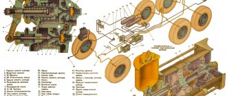
MAZ brake diagram
1 5336-3519210 Front brake chamber 1 5336-3519210 Front brake chamber 2 6422-3506094 Hose to brake valve 2 6422-3506094 Hose to brake valve 3 64229-3506283-10 Tube 4 13.351531 0 Control valve 5 64229-3506130-10 Tube 6 64229-3506282-10 Tube 7 100-3514008 Valve with lever assembly 8 6422-3506142-10 Tube 9 5336-3509012 Compressor 10 64226-3506316 Tube 11 C40-3721000 Pneumatic signal 12 11.3511010 Water separator assembly 13 5336-3506187-01 Hose 14 100-3512010 Pressure regulator assembly 15 6422-3506085-01 Hose 15 6422-3506085-01 Hose 15 6422-3506085-01 Hose 15 6422-3506085-01 Hose 16 100-3536010 Anti-freeze fuse 17 943.702.120.0 Four-circuit valve 18 64229-3506148-20 Tube 19 008-011-19-2-3 O-ring 20 012-016-25-2-3 O-ring 21 100-3570110 Engine stop cylinder 22 100-3570210 Cylinder 23 5551-357023 4-01 Tube 24 6303-3513015-10 Receiver A40-280 25 5336-3513015 Receiver 25 5336-3513015 Receiver 26 5336-3570230 Tube 27 64229-3506258 Tube 28 64229-3506154 Tube 29 64229-3506240-20 Tube 30 53362-3506178 Tube 31 64221-3506180 -20 Tube 32 5336-3506319 Tube 33 943.002.521.0 Trailer control valve 34 64229-3506248-20 Tube 35 54323-3506146-10 Tube assembly 36 53362-3506289 Tube 37 642 29-3506183-10 Tube 38 64229-3506243-20 Tube 39 64229-3506132-10 Tube 40 53362-3506336 Tube 41 53362-3506337 Tube 42 53361-3506136 Tube 43 64229-3506305 Tube 44 53362-3506188 Tube 45 11-3518010 Accelerator valve 46 53361-3506158 Tube 47 53361-3506280 Tube 48 5336 -3519200 Rear brake chamber 48 5336-3519200 Rear brake chamber 49 500-3506060-B2 Hose assembly 50 100-3533010 Brake force regulator 51 64226-3521110 Connecting head 51 64226-3521110 Head connecting 52 014-018-25-2-3 O-ring 53 375960 Washer 54 250636 Nut М16х1,5-6Н 55 250159 Washer 16 56 63031-3521050 Bracket 57 401509 Nipple 58 201497 Bolt М10-6gх25 59 252136 Sha yba 10 OT 60 252536 Nut M10-6N 61 64221-3537020-20 Tube 62 961.702.005.0 Brake valve 63 64229-3506184-20 Tube 64 64229-3506139-20 Tube 65 100-3537110 Brake valve 66 16. 3741000 Pneumatic signal valve 67 100-3562010 Dual-mag valve line 68 64226-3570240-10 Tube 69 64226-3570212-10 Tube 70 54325-1115042 Tube 71 5551-1115040 Tube 72 6303-3506183 Tube 73 64229-3506194 Tube 75 53362-3506289 Tube 76 64229-3506243-20 Tube Link to this page: https://www.kspecmash.ru/catalog. php?typeauto=2&mark=11&model=96&group=138
Adjustment
In serviceable and adjusted brakes, the gap between the lining and the inner surface of the drum should not exceed 0.4 mm. This corresponds to the movement of the TC rod by 25-40 mm. If this value increases to 45 mm or more, then adjustment of the brakes is necessary. Most drivers prefer to do this work with their own hands.
Adjustment work involves sequentially performing the following actions:
- placing the axle on a jack;
- releasing the worm screw of the adjusting lever from the locking plate;
- turning it until the rotating wheel begins to brake;
- rotation of the worm in the opposite direction by 1/3 of a turn, which will correspond to a rod stroke of 25-40 mm.
- return the stopper to its original position.
It must be remembered that the difference in stroke of the TC rod on one axis should not be more than 8 mm. Serviceable brake systems will ensure safe movement and parking of the car.
Adjusting the brakes
In the brake valve drive (Fig. 10), the angle of 45°+2° is adjusted by bolt 2. After adjustment, tighten nut 3 to a torque of 11.8–15.7 Nm. The pedal free play should be 17-27 mm.
Adjustment is made by changing the length of rod 4. After adjustment, tighten nut 5 to a torque of 23.5–35.3 Nm.
When installing the adjusting lever (Fig. 1), the stroke of the brake chamber rods should be within 25-40 mm. When the rod stroke increases to 45 mm, the brakes must be adjusted. In this case, the difference in the stroke of the brake chamber rods on each axle should not exceed 8 mm.
Adjust the brake mechanisms in the following order:
— lift the wheel with a jack;
— loosen bolt 6 and move up the locking plate 7 of the adjusting lever of the expansion fist; — rotating worm 3 (in this case, the brake chamber rod should not move out of the chamber), spread the brake pads until they contact the working surface of the drum;
- turn the worm in the opposite direction by about 1/3-1/2 turn, lock the worm axis by sliding the plate to its original position and securing it with a bolt;
— check that the rod stroke corresponds to the permissible limits;
— check that the drum does not touch the pads in the released position.
Check the stroke of the brake chamber rods at an air pressure in the pneumatic system circuits of 0.56±0.04 MPa (5.6±0.4 kgf/cm 2 ). When taking measurements, the brake force regulator lever should be turned upward to the maximum angle allowed by the design.
When installing the adjusting lever (Fig. 2), the stroke of the brake chamber rods should be within 38...44 mm. The stroke of the rods is not adjusted during operation.
After replacing the linings, as well as when replacing the adjusting lever or brake chamber, it is necessary to adjust the stroke of the brake chamber rods.
— install the adjusting lever on the expansion cam shaft so that the distance from the brake chamber fork to the lever is 20-80 mm.
In this case, the lever should be positioned with the plug forward along the brake chamber rod when braking, and with the hexagonal end of the worm shaft facing the brake chamber (when replacing on the rear axle, brake chambers with spring energy accumulators must be released);
— by rotating the hexagonal end of the worm shaft counterclockwise, you should feel the clicks of the reverse clutch, align the holes of the chamber rod fork and the lever and connect the lever to the fork with your finger.
In this case, the expansion cam shaft must remain in its original position under the action of the tension spring of the pads;
— turn the lever lever all the way (in the direction of rotation of the lever when braking) and secure the lock in this position;
— adjust the stroke of the brake chamber rod by successively pressing the brake pedal all the way at a compressed air pressure in the system of at least 600 kPa (6 kgf/cm2), until a constant value of the rod stroke is established within the range of 38-44 mm.
Caring for the adjusting lever (Fig. 2) consists of periodically lubricating it through the grease nipple 18 until the grease leaves the safety valve 19.
During operation, periodically monitor the operation of the levers by measuring the stroke of the chamber rod. The difference in rod strokes should not exceed 5 mm. If an increased code is detected, check the correct installation of the lever or find out the cause of the malfunction and eliminate it, for which purpose disassemble the lever with cleaning and washing of the parts.
Disassembly is carried out in the following order:
— unscrew plug 6, having previously unlocked it;
— remove spring 5 with coupling half 3;
— remove cover 12 with driver 13 and control ring 14 assembled and gasket 17, pusher 2;
— remove worm 7 with half-coupling 4 assembled;
The lever is assembled in the reverse order. Screw plug 6 until it stops with a torque of 2-3 Nm (0.2-0.3 kgf-m) and unscrew it by 15-20°, having previously lubricated the thread with sealant.
Secure the plug by pulling the collar into the groove of the body. Lubricate the lever through the grease nipple 18 until the grease comes out of valve 19.
Adjusting the parking brake
As the parking brake pads wear, it is necessary to adjust the gap between the brake pads and the brake drum. To do this you need:
— hang up the wheels of the middle axle (or one of the wheels);
— set lever 1 (see Fig. 6) to the “released” position, while the rack of lever 5 (see Fig. 5) should be in the forward extreme position (the parking brake warning light should go out);
Types of system
In addition, it is also necessary to mention the presence of a braking system for the semi-trailer, which is equipped with special pneumatic drives designed to operate other systems powered by compressed air.
Their advantage is that it stops all existing MAZ wheels. The presence of a pneumatic drive with separate braking makes it possible to stop a pair of front and rear wheels.
The main function of spare brakes and parking brakes is to influence axle mechanisms that are activated as a result of the action of spring-loaded energy accumulators and cameras, which are activated by the driver of the vehicle using a special crane located in the cabin.
The parking stopping system is considered additional, and it is used as a last resort, for example, when the service brakes do not work or fail for a number of reasons. When operating it, it is necessary to position the crane handle so that it is in the extreme position.
The air compressing the springs enters the atmosphere, and other mechanisms begin to work, which turn on the handbrake. When the emergency braking system is activated, the control valve handle should be in the middle; no additional effort should be made to move it. It is important to know that as the crank speed increases, the braking force increases due to the decrease in air affecting the springs.
Assisted braking
This type of system works by using gases entering the car system. Its main function is to stop and hold the MAZ on steep roads.
It is combined with a parking one for greater convenience and additional reliability. The auxiliary brake is a special retarder for the motor-pneumatic type. The semi-trailer braking drive is constructed from elements of two and one wires. In winter, you may encounter condensate freezing, especially for large vehicles such as the MAZ, but even here the developers have thought through everything and secured the car by introducing a fuse that eliminates this problem.
The vehicle also has an installation that allows you to reduce traffic on the highway. It consists of a special cylinder and valve system. Added to all this is traction control. To turn it on, you need to use a special button.
Traction control and speed limiting systems help in the supply of compressed air, which is supplied through a proportional valve. It is important to take into account that during simultaneous braking of the MAZ the semi-trailer also stops, because these systems are interconnected.
The design of the MAZ brake system and how to troubleshoot it
The MAZ (TS) brake system serves to ensure safety when the truck is moving and secure it in the parking lot. Structurally, it is made in the form of four independent systems: working, parking, spare and auxiliary. In normal driving mode, a working vehicle is used, but if it fails or emergency braking is applied, all brakes are activated.