Why won't the starter start? Page 13 of 69
Questions can only be asked after registration.
Please login or register. Need help guys. Today we disassembled the PD 10 launcher and found that the bearings were loose and the seals were finally torn. If anyone knows the numbers of the crankshaft bearings and seals, please tell me. And also, what should be the gap at the joints of the piston rings when you insert them into the cylinder without a piston.
you can see it here
/THAT LIGHT THAT SHELTERS IN THE SPEAKS WILL NOT FALL INTO A HEART SPOILED WITH ANGER/
/ live forever, learn forever /
Need help guys. Today we disassembled the PD 10 launcher and found that the bearings were loose and the seals were finally torn. If anyone knows the numbers of the crankshaft bearings and seals, please tell me. And also, what should be the gap at the joints of the piston rings when you insert them into the cylinder without a piston.
Thanks for the catalog.
How should the launcher starter be positioned correctly at YuMZ with a large cabin? The starter is under the hood and inside the cabin or the starter is out.
We begin to respect people even more after we try to do their work.
The starter is under the hood and inside the cabin or the starter is out.
As far as I know, all of them are inside the cabin. I installed the starter from the combine and everything fit together with the starter housing, but I don’t remember whether I turned it over or not, it was a long time ago.
The starter is under the hood and inside the cabin or the starter is out.
As far as I know, all of them are inside the cabin. I installed the starter from the combine and everything fit together with the starter housing, but I don’t remember whether I turned it over or not, it was a long time ago.
I twisted the plate on which the starter housing is attached, so everything fits, I just had to cut it a little with a grinder, since the main engine does not allow me to put it in place.
Vital, if you have it, post a photo of this slab.
We begin to respect people even more after we try to do their work.
Vital, if you have it, post a photo of this slab.
Listen to the pictures, there is no stove itself, I know that the stove and the casing are aluminum and everything fits without modifications, the casing for the starter is made of two halves, I didn’t install the second one, I left room for the shmorgolka.
I have such a stove.
Damn I couldn't find cast iron or aluminum. And the casing is like yours, made of two halves.
We begin to respect people even more after we try to do their work.
I have such a stove. wink Cast iron, I couldn't find any aluminum. scratch_one-s_head And the casing is like yours, made of two halves. wink
If I’m not mistaken, then I probably have some kind of universal one, there are many positions, in short, everything is in holes. But what is not 100% cast iron
+++ I wish for our land of peaceful sky above our heads, and for those who want to spare us - peaceful land above our heads
Why bother, I have an original YuMZ.
Why bother, I have an original YuMZ.
So, just in case, maybe it will be useful to someone else.
+++ I wish for our land of peaceful sky above our heads, and for those who want to spare us - peaceful land above our heads
Why bother, I have an original YuMZ.
I don’t know about Zaporozhets, it seems that it has a bendix of the wrong rotation, and on PD10 starters all the starters are the same, although they also had a mechanical drive for turning on the bendix, without a retractor.
We begin to respect people even more after we try to do their work.
Today the problem arose again; the store did not have gaskets between the crankcase halves and under the cylinder.
You can cut them out yourself. And what can they be cut out of?
We begin to respect people even more after we try to do their work.
Today the problem arose again; the store did not have gaskets between the crankcase halves and under the cylinder.
You can cut them out yourself. And what can they be cut out of?
+++ I wish for our land of peaceful sky above our heads, and for those who want to spare us - peaceful land above our heads
Today the problem arose again; the store did not have gaskets between the crankcase halves and under the cylinder.
You can cut them out yourself. And what can they be cut out of?
It will hurt how thick it is. But simple release paper will not work.
We begin to respect people even more after we try to do their work.
Today the problem arose again; the store did not have gaskets between the crankcase halves and under the cylinder.
You can cut them out yourself. And what can they be cut out of?
It will hurt how thick it is. But simple release paper will not work.
paper will also do, but I had one time where it got sucked in, and then it sucked and the gaskets were torn out, I installed 0.5 mm. I installed it. If it’s not there, the paper will work, just not very thick.
+++ I wish for our land of peaceful sky above our heads, and for those who want to spare us - peaceful land above our heads
And what can they be cut out of?
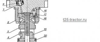
Crankshaft oil seal, front 10
Please provide your name and phone number so we can contact you
Attention: minimum order is 1000 rubles.
The repair kit is used to repair the PD-10 engine (with gearbox) MTZ-80, MTZ-82. The complete set is compiled in accordance with reference and technical manuals and catalogs of assembly units of components and assemblies. The repair kit is packaged in durable packaging, which allows you to preserve the quality and quantity of components.
The contents of the repair kit are presented in the table.
Unit name
Catalog number
Crankshaft oil seal PD
Applicable:
– MAZ: power steering distributor
– MTZ: FDA, PD-10, final drive gearbox
– T-25: steering
– T-40: clutch, gearbox PD-8
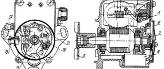
Starting engine PD-10M two-stroke, gasoline, single-cylinder. Its power is 10 liters. With. at 3500 rpm. Installed on the right side of the diesel engine on the flywheel housing. The base of the engine is the crankcase, consisting of 4 front and 12 rear halves (Fig. 85, a). Both halves are pressed against each other with polished planes and form a hermetically sealed crank chamber.
contents .. 41 42 ..CHAPTER 12
POWER TRANSMISSION MECHANISMS OF PD-10M STARTING DEVICE. CARE OF THE STARTING DEVICE, ITS FAULTS AND THEIR REMOVAL
§ 57.
Clutch starting motor PD-10M
The power transmission mechanisms are enclosed in a cast-iron housing 5 (Fig. 99), which, with a guide collar, fits into the hole in the rear beam 16 of the diesel engine and is bolted to it. A vertical partition inside divides the body into 6 front and 29 rear compartments. The front compartment houses the clutch, and the rear compartment houses the gearbox.
The upper plane of the housing is used to install the starting motor.
There is a threaded hole in the bottom of the housing for draining oil. It is closed with plug 13.
The clutch (Fig. 100) is designed to smoothly connect the crankshafts of the starting and main engines and disconnect these balls when changing gears. To stop the clutch shaft more quickly when turning it off (this is necessary for shock-free engagement of one or another gearbox gear), it is equipped with a special brake.
All parts of the clutch are assembled on a steel shaft 2, which rotates on two ball bearings 3 and 16.
The rear end of shaft 2 is drive gear 1. At the end of this gear there is a bore in which the front ball bearing 28 of the automatic shutdown shaft is installed.
On shaft 2 there is a gear 4 mounted on a bronze bushing 6, made in one piece with a drum having four slots.
Inside the gear drum 4 there are steel disks: support 7, five driving 8, five driven 9 and pressure 10.
The drive disks have four protrusions along their outer contour that fit into the slots of the drum. The first driving disk is located behind the supporting disk, and behind each driving disk there is a driven disk. Behind the fifth and last driven disk there is a pressure disk. There are three grooves in the central holes of the support, driven and pressure disks. Three segment keys 11 installed on shaft 2 freely fit into them.
This connection of the shaft with the support, driven and pressure disks allows the disks to rotate with the shaft and move freely along its axis.
The rotation of the crankshaft of the starting engine is transmitted through the intermediate gear 3 (Fig. 99) by the gear (Fig. 100), with which the drive disks 8 rotate.
If the driven disks 9 are not in contact with the driving disks and the latter pass freely between the driven ones, then gear 4 will rotate freely on shaft 2. In this position of the driven and driving disks, the clutch is disengaged.
If the driven disks are pressed against the driving disks with force, then friction arises between them, causing them to rotate together. As a result, the rotation of gear 4 is transmitted to shaft 2. In this position of the driven and drive disks, the clutch is engaged.
Compression and separation of the clutch discs is performed by moving the steel coupling 14, loosely mounted on shaft 2. The coupling 14 has three grooves on the inner surface, with inclined cuts made on one side. The long curved arms of the levers 13 enter into these grooves on the side of the inclined cuts. The levers can freely rotate on the axes 12 in the slots of the cross 25 screwed onto the threads of the shaft 2. The short arms of the levers rest against the pressure disk.
To prevent the cross from rotating on the shaft during operation, it has a lock, the rod 24 of which is under the action of a spring 26
fits into one of the holes at the end of the pressure plate.
The movement of the coupling 14 is carried out by a special mechanism with a lever 3 on the outside (Fig. 101).
Rice. 99. Power transmission mechanisms of the starting device: 1 - drive gear; 2 - shaft; 3 — intermediate gear of the starting motor; 4 — clutch gear; 5 — housing of power transmission mechanisms; b — front compartment of the body; 7 — brake housing; 8 — front ball bearing; 9 — rear ball bearing; 10 and 11 — channels for supplying oil to the bushings of the intermediate gear block; 12 — bushing of the intermediate gear block; 13 - plug; 14 — block of intermediate gears; 15 — axis of the intermediate gear block; 16 — diesel rear beam; 17 — rear ball bearing of the automatic shutdown shaft; 18 - bolt; 19 — drive gear; 20 — pusher; 21 - weights; 22 — transverse spring; 23 — axis of the pressure lever; 24 — pressure lever; 25 — self-clamping oil seal; 26 — cover of the rear ball bearing of the automatic switch; 27 — intermediate sleeve: 28 — nut; 29 — rear compartment of the body; 30 - movable gear; 31 — automatic shutdown shaft; 32 - front ball bearing of the automatic shutdown shaft.
Rice. 100. Clutch coupling of the starting engine: a - section; b - coupling details; 1 - drive gear: 2 - shaft: 3 - rear ball bearing; 4 - gear; 5 — channel in the gear: b— bushing: 7 — support disk; 8 — drive disk; 9 — driven disk; 10—pressure disk; 11 — segment key; 12 — lever axis; 13 — cross lever; 14 - movable coupling; 15 — brake housing; 16 — front ball bearing; 17 - nut; 18 — brake housing cover; 19 — oiler: 20 — brake hub; 21 — fixed brake disc; 22 — rotating disc brake; 23 — lock button; 24—locking rod; 25 — cross; 26 — clamp spring; 27 — hole in the bushing; 28 — ball bearing of the automatic shutdown shaft.
When lever 3 moves to the right, clutch 14 (Fig. 100, a) moves along shaft 2 to the left. At the same time, with inclined cuts of the grooves it presses on the long arms of the levers 13, forcing the levers to rotate around the axes 12. When turning, the short arms of the levers will press on the pressure plate 10, which, moving along the shaft 2, will compress the drive and driven disks, turning on the clutch. In the engaged position, the clutch is held due to the fact that the long arms of the levers are inserted into the horizontal part of the grooves.
When lever 3 (Fig. 101) moves to the left, clutch 14 (Fig. 100, a) will move along shaft 2 to the right. In this case, the long arms of the levers 13 will come out onto the inclined cuts of the grooves, and the short arms of the levers will move away from the pressure plate. The compression of the driving and driven disks will stop, the clutch will disengage, and gear 4 will rotate freely on the stationary shaft 2.
The clutch brake is located in the housing 15 and consists of two fixed disks 21 and two movable (rotating) disks 22.
The fixed discs fit with their protrusions into the slots on the protruding shoulder of the brake body. The rotating discs are slotted and freely mounted on the protrusions of the brake hub 20, which is secured to a key on shaft 2.
When the clutch is engaged, there is a gap between the stationary and rotating brake discs, and therefore the discs 22 rotating with the clutch shaft freely pass between the stationary discs 21. At the moment of disengagement, the clutch 14, moving along the shaft 2 to the right, will press the rotating brake discs with its end face against motionless and will cause a quick stop of shaft 2.
The clutch and brake discs rotate in oil poured into the housing of the power transmission mechanisms.
The rubbing surfaces of shaft 2 and bushing 6 are lubricated by oil supplied to them through channel 5 in gear 4 and hole 27 in the bushing when the gear rotates.
Rice. 101. Control levers for the power transmission mechanisms of the starting device: 1 - control lever for the automatic switching off of the starting engine; 2 — gear shift lever: 3 — clutch control lever; 4 - plug; 5 and 7 — rollers; b - cover; 8—coupling bolt; 9 - leash; 10 and 15 — screw stops; 11 and 16 — springs; 12 and 17 - balls; 13 ~ fork axis; 14 - fork; 18 — lever: 19 — key, 20 — clutch housing; 21 - drive gear.
§ 58.
Starting motor gearbox PD-10M
A two-stage gearbox installed in the rear compartment 29 (Fig. 99) of housing 5 is designed to increase the force on the drive neck-turn 19. This is necessary for the initial cranking of the diesel crankshaft.
The gearbox consists of a drive gear 1, a block of intermediate gears 14, an axle 15, a gear 30, an automatic shutdown shaft 31 and a gear shift mechanism.
The drive gear 1 of the gearbox is in constant mesh with the large gear of the gear block 14, which rotates freely on a fixed axis 15. The bronze bushings 12 of the gear block are lubricated with oil supplied to them through channels 10 and 11 in axis 15.
The steel shaft 31 of the circuit breaker rotates in two ball bearings 32 and 17.
A steel gear 30, which has external and internal teeth and a circular groove on the hub, is freely mounted on the splines of the shaft 31. When the gear 30 moves along the splines, the transmission of the gearbox changes, as a result of which the rotation speed of the automatic shutdown shaft changes.
Gear 30 moves along the shaft using a gear shift mechanism, which is assembled on cover 6 (Fig. 101).
When lever 2 moves to the left, a slow (first) gear is engaged, since lever 2 with a fork 14 moves gear 30 (Fig. 99) to the left, and with its outer teeth it will engage with the small gear of the gear block 14. In this case, the rotation is from the drive gear 1 through the gear block 14 and gear 30 will be transferred to the shaft 31 of the automatic shutdown.
When lever 1 (Fig. 101) moves to the right, accelerated (second) gear is engaged, since lever 2 with fork 14 will move gear 30 (Fig. 99) to the right, and with its internal teeth it will engage with the teeth of drive gear 1. Rotation of shaft 2 will be transferred to the shaft 31 of the circuit breaker.
On the axis 13 (Fig. 101) of the fork, two annular grooves are machined into which, when the gear is engaged, the latch ball 12 enters, holding the gear 30 in the installed position. Since the neutral position of gear 30 is not fixed, it cannot be installed in this position.
The gearbox parts are lubricated with oil sprayed when the gearbox gears rotate. Oil is poured into the housing of the power transmission mechanisms through the hole in the front half of the crankcase, closed by plug 12 (Fig. 88), to the level of the hole closed by plug 4 (Fig. 101).
The oil is drained through a hole closed by plug 13 in the bottom of housing 5 (Fig. 99).
contents .. 41 42 ..
PD-10 starting motor diagram
Rice. 85. Starting motor PD-10M - diagram (starter PD-10). a) Longitudinal section, 1—intermediate plate; 2—crankshaft gear; 3—idler gear; 4—front half of the crankcase; 5—ball bearing; 6 and 14—oil seals; 7—front roller bearing; 8 — front axle shaft of the crankshaft; 9—crankshaft cheek; 10—connecting rod roller bearing; 11—pin (crankpin) of the crankshaft; 12—rear half of the crankcase; 13—rear roller bearing; 15—felt seal; 16—flywheel; 17 – rear axle shaft of the crankshaft; 18—connecting rod; 19—lubrication channel; 20—piston; 21—piston pin retaining ring; 22—piston pin; 23—gas outlet pipe; 24—exhaust window; 26—under-discharge pipe; 26—glow plug; 27—filler tap; 28—cylinder head; 29—head gasket; 30—cylinder; 31—blow-out window; 32—inlet window; 33—carburetor; 34—thrust from the regulator to the carburetor; 35—magneto, b) Section of the cylinder in a horizontal plane, c) Gears: 36—regulator drive gear; 37—regulator drive gear.
To ensure a tight connection, the planes are lubricated with shellac.
Diagram of the PD-10 starting motor
The starting motor of this brand consists of a number of components and appears to be a complex technical unit designed to ensure a stable start of the MTZ tractor engine. Studying its structure, the following key design elements can be identified:
- cylinder. Attached to the crankcase using nuts. Purge channels, strategically located tangentially to the circumference of the unit, reduce leakage of the mixture into the exhaust. The cylinder head is equipped with a spark plug;
- piston. Made from high-strength aluminum alloy. Its distinctive feature is a spherical bottom, which improves the quality of cleaning the cylinder from exhaust gas. If you want to achieve the correct position of the piston, you should place it so that the arrow on its bottom points towards the rear axle shaft of the crankshaft;
- connecting rod mechanism. Made of special grade steel, equipped with a bronze bushing. The mechanism heads are one-piece, and the bearing is double-row, roller type;
- gears;
- crankshaft. Roller bearings with rubber seals act as its support. In order to equalize the centrifugal force, the knees of the cheeks are equipped with special weights;
- The cooling system of the unit is connected to a similar system of the main motor.
Be sure to read: MTZ 82 brake design
These elements are key and take the most active part in the operation of this engine. At the same time, there are many other components, such as pins, rings, windows and other components.