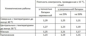
Tire pressure control system
Central tire inflation diagram
1, 14, 60. Hoses. 2, 3, 8, 11, 13, 15. Pipelines. 4. Single protective valve. 5, 10, 12, 17. Tees. 6. Solenoid valve. 7, 18, 19, 59. Angles. 9, 16, 20. Fitting. 21. Tube to tire pressure gauge. 22. Tire.
23. Camera. 24. Rim tape. 25. Side ring. 26. Key ring. 27. Valve groove seal ko/ 28. Wheel crane. 29. Rim base with discs.
30. Block - crankcase. 31, 45. Crankcase covers. 32. Crankshaft. 33. Cuff. 34.44. Bearings. 35. Connecting rod. 36. Piston. 37. Piston pin. 38. Compressor head. 39. Discharge valve seat. 40. Discharge valve. 41. Valve spring. 42. Discharge valve plug. 43. Nut. 46. Seal.
47. Electromagnet. 48. Anchor. 49. Breather. 50, 53, 57. O-rings. 51. Valve. 52. Valve seat. 54. Hairpin. 55. Cover. 56. Housing. 58. Air supply cuff block. 61. Protective casing.
Source
Cabin
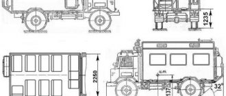
Considering the model of the Urals, it is impossible to note any obvious features inherent specifically to it. In most trucks, much emphasis is placed on technical properties, but certainly not on the design and interior of the cabin. But if you still identify some special features, then you can note the presence of three seats for the driver’s personnel and in some modifications there is one berth for a fourth passenger.
Starting in 2009, the car was equipped with an improved variation of the cabin, which was based on fiberglass. This version of the cabin boasts more interesting operational properties, and the degree of driving comfort has become much higher. This is largely due to the use of more comfortable and practical seats, which have the ability to be adjusted to suit the individual driver of the Ural 4320.
You can't ignore the car's steering, which in most trucks is, to put it mildly, not the simplest. In our case, we also get power steering, which greatly simplifies the operation of the truck, making the driving process more enjoyable.
The materials from which all on-board instruments are made are very worthy plastic, with an increased level of strength. There is nothing unusual about this, but if we talk about the service life of the steering wheel, control panel, and other devices, then this has already been checked and no problems in operation have been noticed. The same can be said about the seats, which are covered with high-quality material that does not suffer from wear and tear over years of active use. There are, of course, exceptions to this, but if we take the majority of trucks, then such a problem has not been noticed.
Tire pressure control system
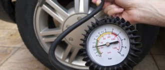
The tire pressure regulation system allows you to control the pressure and maintain it within normal limits, as well as increase the vehicle's cross-country ability by reducing the air pressure in the tires. It makes it possible to continue driving the vehicle if the tires are damaged without replacing the wheel (the wheel valves of undamaged wheels must be closed), if the supplied air is sufficient to constantly maintain the required pressure in the tires.
The vehicle is equipped with a tire pressure regulation system with a pressure control valve or with solenoid valves.
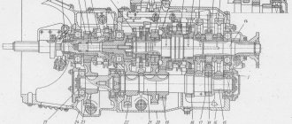
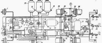
When installing a tire pressure control system on a vehicle with a pressure control valve (Fig. 107), the air supply to the tires is made according to a single-wire circuit. The tires of all wheels with open valves are connected to each other, the pressure in them is the same and is simultaneously regulated by the pressure control valve.
The control is carried out by a valve lever from the driver's cabin and has three positions: tire inflation, neutral and tire deflation. The actual air pressure in the tires is shown by the pressure gauge with the control valve lever in neutral and the wheel valves open.
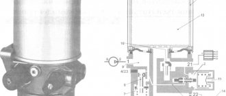
Rice. 107. System for regulating air pressure in tires with a control valve: 1 - supply fitting; 2, 16, 21 — hoses; 3, 7, 15, 19 — squares; 4, 6, 8 — pipelines; 5, 17 — tees; 9 — cross; 10 — output tube; 11 — pressure control valve; 12 — crane control lever; 13 — tube to the pressure gauge fitting; 14 — air cylinder; 18 — air supply cuff block; 20 — hub cover
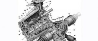
Due to the different load on the rear and front axles, the air pressure in the tires is different. At the nominal tire pressure, the wheel valves of the rear axle should be closed and the front axle should be open. If it is necessary to change the tire pressure, open the wheel valves of the rear axle and set the pressure according to (see Table 6 in the “Driving” section) depending on the driving conditions. The pressure control valve is of the spool type and consists of a body 7 (Fig. 108), in which cuffs 10 and a spool 12 are installed.
When the spool moves along its axis, the annular groove on it connects the valve cavity with the atmosphere or discharge line. The limiting valve, which serves to turn off the tire inflation system when the air pressure in the car's pneumatic system drops below 600 kPa (6 kgf/cm²), is adjusted with bolt 14.
Rice. 108. Pressure control valve: 1 - spring plate; 2 - spring; 3 - piston; 4 - cover; 5 — washer; 6 - diaphragm; 7 — body; 8 — spacer ring; 9 - 10 - - cuff; 11 — spool guide; 12 — spool; 13 - nut; 14 - bolt; a - into the atmosphere; b - into tires; c - from an air cylinder; I - pumping; II - issue
When installing a tire pressure regulation system with solenoid valves on a vehicle (Fig. 109), the air supply to the tires is made according to a two-wire circuit. The air pressure in the tires is adjusted separately for the tires of the front axle and the rear axle and is set depending on driving conditions (see Table 6 in the “Driving” section). Control is carried out from the driver's cabin using keys 18 and 19 (see figure installed on the instrument panel.
Starting and stopping the URAL-4320-10, URAL-4320-31 engine
Start and stop
The order of operation when starting the engine depends on its thermal state, as well as on the ambient temperature. The electric starting system of the engine ensures its start at temperatures down to minus 10 ° C without heating. At outside temperatures below minus 10 °C, use a heater.
For insufficiently charged batteries and in order to increase engine life, the plant recommends using a pre-heater even at outside temperatures above minus 10 °C.
Starting the engine without heating
The procedure for starting a cold engine at a temperature from 0 to minus 10 °C:
1. Prime the engine system with fuel using a manual fuel priming pump.
2. Set the gearbox control lever to neutral.
3. Close the radiator curtain.
4. Turn on the batteries.
5. Set the engine stop handle to the working position (move it all the way to the panel).
6. Press the clutch pedal all the way.
7. Press the fuel control pedal to a position corresponding to the average crankshaft speed.
8. Without releasing the pedal, turn on the starter by turning the key clockwise all the way to the right.
9. After the engine starts, turn off the starter by releasing the key switch, hold the fuel control pedal in the position corresponding to the average crankshaft speed until the engine begins to operate steadily, and then smoothly release the clutch pedal (the gear shift lever must be in the neutral position) . Use the speed control knob to set the minimum crankshaft speed. The constant rotation speed of the engine crankshaft is set by pulling handle 7 (see Fig. 23) toward you. The handle is connected by rods to the fuel injection pump regulator control lever and is located in the cab on the front panel. If the engine does not start, repeat the start in the above sequence. If after three attempts the engine does not start, find and repair the problem. The starter activation time should not exceed 15 seconds and the intervals between starting attempts should not be less than 1 minute.
Before starting a warm engine, set the fuel supply control pedal to the position corresponding to the average engine speed. Turn on the starter and after the engine starts, release the key switch.
Starting a cold engine using a preheater
When using low-freezing liquid in the engine cooling system, heat it up and start it in the following sequence:
1. Raise the hood and make sure that the heater fuel tank valve is open.
2. Turn on the pumping unit with the switch located on the preheater control panel for 10-15 s.
3. Turn on the electric fuel heating with the switch located on the preheater control panel (spring-loaded activation), and hold the switch handle depending on the ambient temperature for the following time: 30 s - above minus 30 ° C, 60 s - from minus 30 to minus 50 °C.
System for regulating air pressure in tires of a Ural car
The tire pressure regulation system allows you to control the pressure and maintain it within normal limits, as well as increase the vehicle's cross-country ability by reducing the air pressure in the tires.
It makes it possible to continue driving the car if the inner tube is punctured without replacing the wheel (the wheel valves of undamaged wheels must be closed) if the supplied air is sufficient to constantly maintain the required pressure in the tires.
Air supply to tires using a single-wire circuit. The tires of all wheels with open taps are connected to each other, the pressure in them is the same and is regulated simultaneously.
The pressure control valve is of the spool type and consists of a body 7 in which cuffs 10 and a spool 12 are installed.
When the spool moves along its axis, the annular groove on it connects the valve cavity with the atmosphere or discharge line.
The limiter valve, which serves to turn off the tire inflation system when the air pressure in the car’s pneumatic system drops below 600 kPa (6 kgf/cm2), is adjusted with bolt 14.
The air supply cuff block 22 consists of four cuffs installed in the axle (casing) of the bridge.
The cuffs ensure the tightness of the connection between the channels of the stationary axle (casing) and the channels of the rotating axle shaft.
System use and maintenance
After opening the wheel valves, blow air from the tires into the tire pressure regulation system.
To do this, set the control valve handle to the “RELEASE” position, reduce the tire pressure by 0.03–0.05 MPa (03–0.5 kgf/cm2), and then bring the tire pressure to the pressure corresponding to the road surface.
Also purge the air pressure control system before parking the car and after each time leaving a warm garage.
Determine the air pressure in the tires using a pressure gauge with the pressure control valve lever in neutral position and the wheel valves open.
To ensure separate regulation of air pressure in tires on any axle, close the wheel valves on other axles.
If there is a drop in pressure, close the wheel valves and, opening them one by one, determine which tire is leaking air.
Tire pressure depending on road surface
Source
Design features of Ural flatbed trailers
Ural trailers with a frame structure are manufactured using advanced technologies and program-controlled equipment. To ensure high strength, the load-bearing spars are made of high-strength Ovaco steel alloy. Cross beams are mounted along the width of the loading platform to achieve high load capacity. Thanks to the even flooring made of 3 mm rolled sheets, loading and unloading of various types of cargo is facilitated. The corrugated surface prevents slipping. Trailed equipment is equipped with folding sides made of rolled sheets with a cross-section of 2 mm. Reinforcement is provided on the side edges. The side racks are made according to a quick-release design. The lower stops are inserted into hinges welded to the side edges of the platform. The rack locks additionally perform the functions of fixing the sides in the closed position.