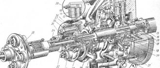
Compressor device
Such a two-cylinder unit has a piston-type device. The main feature of its operation is the pumping of air, performed by the movement of the pistons. Its design consists of the following elements:
- Stuffing box.
- Springs.
- A wire-type catheter with channels.
- Seal.
The pistons themselves are made of aluminum, and also have special fingers secured by retaining rings. Through the inlet valves, air is pumped directly into the compressor cylinders. There it is compressed by pistons and then enters the pneumatic system. It then leaves the compressor through special discharge valves.
Discharge mechanism
The pumping mechanism in the device is very compact in size. According to experts, the device can withstand high pressure. Thus, the price for the ZIL-130 compressor is quite justified. The saddle in the device has two outputs. This part does not come into contact with the rocker arm.
The injection mechanism is connected to the crankcase through a tube. The model uses a small diameter shaft. At its base there are two rings and lubricant for the ZIL-130 compressor. A short plug is installed at the end of the shaft. The exhaust valve of the supercharger is used with a protective sleeve. If there are problems with the air supply, the first thing to check is the blower outlet. Next, unscrew the cap and completely clean the valve. The next step, experts recommend checking the spring, since there is a lot of pressure on it.
Unit repair
Separately, it is worth mentioning how such a unit is repaired if any breakdowns occur in it. Breakdowns may be indicated by noise or knocking that occurs during operation of the compressor, or by oil penetrating into the air cylinder being filled:
- The appearance of cracks or chips on the crankcase itself. To eliminate the damage, a complete replacement of the crankcase is required when the damage is located on the walls. Or they are welded in a situation where they are on the mounting flange and also have small dimensions.
- In order to check the tightness of the cylinder itself, it should be placed in a water bath, and then filled with air under high pressure. The appearance of bubbles will indicate the presence of damage. To eliminate this problem, the container is bored and then honed to the required size.
- When ball bearings become unusable, they are pressed and then replaced with new ones.
- If the crank pin wear exceeds 0.05 mm, a complete replacement of the crankshaft is required.
- In order to repair the upper head of the connecting rod, it is necessary to press in the repair sleeve, where a hole is made in advance. Its diameter should be 14.019 mm.
The permissible repair size of the piston depends on the number stamped on the bottom of the product. Usually this is +04 or +08.
A special repair kit should be in every workshop where it is planned to use such a product. This will allow you to quickly restore the device to functionality.
Plunger mechanism
The plunger mechanism of this compressor is used with a bearing row. Experts say that the part can withstand heavy loads at high speeds
However, it is important to note that the inlet valve needs frequent cleaning. In this case, the channel becomes clogged quite often
To check it, the crankcase is unscrewed. You will also have to remove the cover. An adjusting screw is used to adjust the plunger. When the cover comes out, you can install a large screw. In this case, it is necessary to select the appropriate protective ring. To solve problems with abrasion of the lining, special means are used to seal the block. Some experts recommend periodically cleaning the tubules.
Motorists may also encounter problems with the plunger base. It is a regular plate, which is fixed on a thread. If there is a lot of shaking, the connection breaks down quite quickly. As a result, the plate begins to wobble. To correct this situation, it is recommended to first remove the cover
After this, it is important to immediately clean the outlet. The screw unscrews very slowly
In this case, you need to monitor the position of the bearing row.
How to make your own compressor based on ZIL-130
Depending on the volume of tasks that are planned to be performed on the unit, the number of modifications of the ZIL compressor is determined. Its restructuring is required in a situation where long-term operation under increased loads is planned. To do this you will need the following materials:
- Receiver.
- Pressure gauge mounted on the receiver.
- The power plant itself.
- Safety valve.
When you create a compressor yourself, it is important to correctly transfer torque to it. This is what the valve and pressure gauge will be responsible for. The following features should be taken into account during the assembly process:
- Torque. If you plan to connect the power plant to the unit via a pulley and belt, you will need to use a “stronger” engine due to the loss of some power in this way. Because of this, it is recommended to connect through a reducer, although its price is quite high.
- Engine. This element must be selected so that its power parameters meet the needs of the compressor. So, to ensure the required pressure, the rotation speed must be at least 2 thousand rpm. This will allow the unit to operate in cruising mode without significant loads. For short-term use, options that produce a power of 1 kW are sufficient, but for more intense loads, more powerful products should be used.
- Receiver. Created from a medium-sized metal container. This design is equipped with a pressure gauge, as well as a pressure regulator, which is installed at the outlet. At the entrance to the tank, a unit equipped with a gearbox is installed.
- Cooling system. In certain compressor versions, overheating occurs during operation, which requires additional improvement of the standard cooling system.
The compressor itself must be mounted on the frame in a pre-prepared seat. The engine is also mounted there, and other elements are installed separately and connected via hoses.
Independent creation of a compressor based on the ZIL-130 allows you to get a high-performance unit at little expense. You can buy the necessary elements using an online catalog (for example, Avito), where various devices and parts are sold. Each offer has a photo and description of condition and characteristics. When assembling the device, it is important to take into account the features and subtleties of creating such a design.
If you find an error, please select a piece of text and press Ctrl+Enter.
Plunger mechanism
The plunger mechanism of this compressor is used with a bearing row. Experts say that the part can withstand heavy loads at high speeds
However, it is important to note that the inlet valve needs frequent cleaning. In this case, the channel becomes clogged quite often
To check it, the crankcase is unscrewed. You will also have to remove the cover. An adjusting screw is used to adjust the plunger. When the cover comes out, you can install a large screw. In this case, it is necessary to select the appropriate protective ring. To solve problems with abrasion of the lining, special means are used to seal the block. Some experts recommend periodically cleaning the tubules.
Compressor assembly
The assembly of compressor components must be carried out under conditions that prevent dirt and dust from entering the assembled parts.
Before assembly, the compressor parts must be thoroughly washed in a degreasing solution and dried.
It is recommended to screw in compressor fittings and plugs using AK-20 glue. It is recommended to lubricate sealing gaskets, in addition to the cylinder head gasket, with rubber resin... other sealants.
Installation of crankshaft bearings.
Press the bearings onto the main journals of the shaft using a mandrel model I 806.04.002 and a hammer. The bearings must be seated on the shaft journals within an interference range of 0.002…0‚030 mm.
What do we get as a result?
As a result, we get a device practically for free that is only suitable for inflating tires or for other work that is not demanding on air quality.
Such a compressor is absolutely not suitable for painting and also for pneumatic tools. The compressor turns out to be bad: it heats up after a few minutes and starts throwing condensate into the system. The oil also throws out with terrible force and you have to constantly top it up. In general, it’s still bullshit.
I have been using this compressor for several years now, and all these years I have understood that such things need to be done initially in a normal way with a normal lubrication system and normal cooling. In all these years he has never satisfied me in this form and never will. But if you don’t have money, you’ll have to put up with these disadvantages.
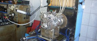
Compressor test
When testing a compressor on a bench, the compressor shaft rotation speed should be 1800...2000 min. The compressor must be supplied with I20A oil, GOST 20799-75
under pressure 0.25...0‚30 MPa (2.5...3.0 kgf/cm2), oil temperature 35...50 °C.
It is recommended to run the compressor at idle speed for five minutes. During the break-in process, you should make sure that there are no oil leaks, overheating of the bearings and that there is no knocking of the pistons, pins and exhaust valves.
At 800...2000 min of the compressor crankshaft and communication of the cylinder 3 with the environment through a calibrated hole with a diameter of 1.6 mm and a length of 3 mm, the pressure in the container after 50 should reach a value of at least 0.6 MPa (6 kgf/cm2).
The compressor is tested for oil throughput at 800...2000 min and an oil pressure of 0.25...0‚30 MPa (2.5...3.0 kgf/ohm2). In this case, the amount of oil flowing through the drain hole of the compressor crankcase cover (with the calibration hole open) should be no more than 220 g per minute.
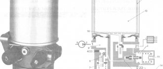
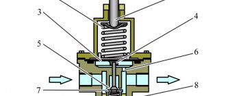
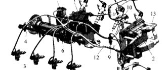
The operation of the unloading system is checked by supplying compressed air under a pressure of no more than 0.5 MPa (5 kgf/cm2) into the channel of the unloading chamber, while the plungers 4 (see Fig. 8 - 11) must rise and fully open the inlet valves 8.
Test stand diagram
When the pressure is removed, the plungers must clearly return to their original position under the action of the return spring. Perform this operation at least three times.
Check the exhaust valves for leaks by connecting the compressor head to cylinder 3 (Fig. 8-13) with a capacity of 1 liter, as indicated in the diagram, at a pressure of 0.60...0‚65 MPa (6.0...6.5 kgf/cm2) . In this case, the pressure drop in the cylinder should not be more than 0.04 MPa (0.4 kgf/cm2) per minute.
Checking the tightness of connections is carried out with a soap solution at an air back pressure of 0.65 MPa (6.5 kgf/cm2).
Before installing a pressure regulator on a compressor, it must be checked, tested and adjusted to operate within the specified air pressure limits.
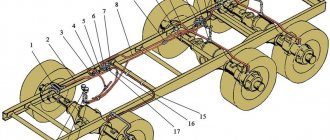
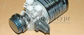
Purpose and location of the pneumatic system pressure regulator
On domestic and foreign trucks, a pneumatic braking system is widely used, which also supplies compressed air to a number of other components and assemblies - the dump platform control system, clutch, sound signal, etc. All these components are built in such a way that they work normally only within a certain pressure range, and if the pressure goes beyond this range (becomes higher or lower), then their operation will become impossible. And an excessive increase in pressure is even fraught with breakdowns.
Therefore, the pneumatic system of trucks must have a component that ensures that the air pressure is always maintained within the operating range. This problem is solved by a unit that is simple in design and principle of operation - a pressure regulator. The pressure regulator performs three functions:
- Disconnects the compressor from the pneumatic system if the pressure in it reaches the maximum permissible value;
- Connects the compressor to the pneumatic system if the pressure in it drops below the minimum permissible value;
- Protects the pneumatic system from excessive pressure growth if, for one reason or another, the compressor was not turned off when the maximum permissible pressure was reached (performs an emergency pressure release).
- Source
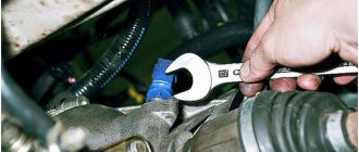
Installing the compressor on the engine.
Install the washers, then manually install the compressor onto the engine, directing the slots of the cover-bracket to the cylinder head studs. Tighten the compressor mounting nuts by hand. Place the drive belt on the pulley, adjust the belt tension and tighten the nuts.
When installing the compressor, it is necessary to ensure a gap of at least 5 mm between the radiator outlet hose and the compressor air pipe. The specified clearance is achieved by turning the radiator outlet hose. The clearance is necessary to prevent chafing of the hose by the compressor pipe.