Bridges GAZ 66
Both axles (both front and rear) have the same gear and differential. In this case, the main transmission (also known as the axle gearbox) is of the hypoid type. There is a downward displacement of 3.2 cm at the axis of the drive gear. The beams on both bridges have a box section.
Rear axle device
Considering in detail the structure of the rear axle, its main details should be noted:
- Two axle shafts of the rear axle, as well as axles.
- Assembled gearbox.
- Carter.
The car's axles provide it with good cross-country ability.
The last element has a long and elongated body, which has a thickening and a special hole through which the gearbox is installed. It is also the main driving element of the bridge itself, which not only changes the gear ratio, but also drives the wheels at a certain speed. The GAZ 66 rear axle gearbox itself includes a number of elements:
- Frame.
- Bearings.
- Assembled differential.
- Main transmission gears.
Front axle
Separately, it is worth mentioning the design of the front axle of the GAZ 66. Its gearbox design is completely similar to that of this element in the rear version, which can be seen in the drawing. But there are certain differences in the design of the case. Instead of axle shafts, it contains joints (CV joints). These units include the following elements: driven and driven fists, as well as 4 balls.
content .. 41 42 49 ..GAZ-66-11. Rear axle repair
From the car
. Disconnect the driveshaft from the flange
10 (see Fig. 108) drive gear; unscrew the wheel nuts and remove the wheels; unscrew the nuts securing the spring ladders and remove the ladders, pads and spring linings; unscrew the shock absorber mounting nuts and remove the shock absorbers; disconnect the hoses of the brake system and tire pressure regulation system; install the bridge on the stand.
Rear axle disassembly
. Before disassembling the rear axle, unscrew the drain plug and drain the oil. Remove cover 3 (see Fig. 86) of the axle shaft flange and the gasket, and remove the sealing ring. Unscrew the nuts securing the axle shafts and remove the axle shafts using bolts for dismantling. Remove the axle flange gasket. Unscrew the lock nut 4 securing the outer hub bearing, remove the lock washer 5, unscrew the hub fastening nut 6. Remove the brake drum assembly with hub 7, take out the inner ring and press out the outer ring of the outer hub bearing. To do this, use a puller with a grip installed in it. Paws
1 (Fig. 109) of the gripper is brought under the end of the ring and pulled apart until it stops by screwing bolt 2 into axis 4. Remove the bearing ring by rotating screw 3.
Remove the oil seal, support washer and inner race of the inner bearing of the hub. Press the outer ring of the inner bearing out of the hub using a puller with a grip, remove the protective bushings from the brake shield and the outer oil seal housing, unscrew the axle mounting nuts and remove the outer hub oil seal, brake pads, axle assembly with the pumping oil seal block, axle shaft oil seal and gasket. Unscrew the flexible hose from the oil seal block, press out the axle shaft oil seal and disconnect the oil seal block and the axle. Unscrew bolts 31 (see Fig. 108) securing the gearbox to the rear axle housing, remove the gearbox using the dismantling bolts, remove the gasket, and unscrew the breather.
Disassembling the gearbox
. Unscrew the plug 17 from the neck of the gearbox housing, the oil pickup tube plug, the bolt and remove the locking plate. Remove tube 1, spring, plate from the oil channel; Unlock and unscrew the adjusting screw 4 of the driven gear stop. Remove the bushing and spring ring from the adjusting screw. Unscrew and unscrew the bolts securing the locking plates and differential bearing caps, remove the locking plates 23, unscrew the adjusting nuts 20 and remove the bearing covers 24.
Before removing the covers, pay attention to the marks (in the form of identical numbers) that must be placed on the outer surfaces of the covers and the side surfaces of the gearbox housing in order to avoid unacceptable disassembly of these parts (since at the factory, boring holes and threading were carried out in the housing with already installed covers ). Remove the outer rings of the differential bearings and their adjusting nuts. Before removing the adjusting nuts and bearing caps, mark the nuts and bearing caps to ensure they are in the same position during reassembly. Remove the differential assembly from the crankcase, unscrew the bolts 13 securing the drive gear bearing clutch, press the drive gear assembly 9 out of the gearbox housing, remove the adjusting shims 5 from the crankcase neck. Dismantling the drive gear
. Undo the nut 8 on the shank of the drive gear, unscrew the nut and remove the washer, remove the flange 10 of the propeller shaft, remove the front cover 7, gasket and oil removal ring 12. Remove the bearing clutch 14 together with the inner ring of the front tapered bearing, adjusting ring /5, inner ring rear tapered roller bearing.
To do this, use a puller, installing insert 1 into it (Fig. 110). In this case, the nuts 3 compress the supports 2 until the liners contact the bearing race and the rotation of the screw 4 compresses the bearing ring. Press out the oil seal 11 (see Fig. 108) of the drive gear from the front cover. Remove the retaining ring of the cylindrical roller bearing and compress bearing 18. If the outer rings of the bevel bearings of the drive gear are unsuitable, they are removed. When repairing bearing couplings, it is taken into account that at the factory, after boring the bearing seats and pressing the outer bearing rings into them, further processing of the coupling is carried out on the basis of these rings. When repairing a bridge, whenever possible, use a coupling without pressing out the outer rings of the bearings.
Rice. 109. Pressing out the outer ring of the hub bearing
Rice. 110. Removing the inner ring of the rear bevel bearing of the drive gear
Disassembling the differential
. Unscrew and unscrew the nuts of the bolts securing the driven gear to the differential cup and separator, remove the bolts, disconnect cup 22 and separator 28, remove the outer sprocket 27,
take out the inner sprocket 30, take out the crackers 25. Remove the driven gear 26 from the cup, the inner race of the differential bearing, and the inner race of the differential bearing from the separator.
content .. 41 42 49 ..
Parameters and weight of GAZ-66 bridges
Speaking about the technical characteristics of the GAZ-66 axles, which provide good cross-country ability for the truck, it should be noted the design features of the vehicle’s suspension and transmission:
- The presence of several driving axles at the same time.
- The presence of slopes on each axis.
- Almost identical dimensions of the rear and front axles.
- Possibility of using reduced speed via transfer case.
Be sure to read: GAZ 3307
This design itself can be turned off, and CV joints are used to turn the wheels. But at the rear there are axle shafts, which are provided with movement through a gearbox. In this case, there is a self-locking differential, which is ensured by blocking the movement of gears. This allows you to create synchronized movement of all drive wheels. This process is controlled by the driver from the cab. However, in this form the car cannot move on roads equipped with dense surfaces, or at high speeds. This is due to the fact that the torque is too high and can even break the axle shaft. The bridges themselves have the following parameters:
- Track size front and rear: 1.8/1.75 m.
- Weight of the front and rear structure when assembled: 350/270 kg.
- The gear ratio is 6.83.
- The gears of the main pairs are bevel.
The design used at the rear of the GAZ-66 is in many ways similar to that used on the GAZ-53. However, the latter lacks the ability to lock the differential, but this cannot be seen in the photo of the axles.
Construction of the GA-Z66 bridge
TRUCKS GAZ, ZIL, KAMAZ, URAL, MAZ, KRAZ
_________________________________________________________________________________________
Design and adjustment of the GAZ-66 drive axle
The main gear and differential of the front and rear axles of the GAZ-66 are the same. The main gear (reducer) of the GAZ-66 is hypoid type: the displacement of the drive gear axis is directed downwards and is equal to 32 mm.
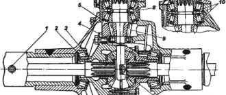
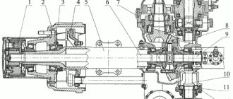
The front and rear axle beams are box-section. The design of the front axle steering knuckle is shown in Fig. 1.
Fig.1. Drive to the front wheels of the GAZ-66 car 1—wheel; 2 — oil seal block; 3—king pin; 4—steering knuckle lever, 5—bushing; b - oil seal; 7—ball joint; 8—leading fist; 9—trunnion; 10—brake; 31—drive flange; 12—air supply channel; 13 — flange cover; 14, 15 — bearing nuts; 16 — lock washer; 17—footboard; 18 — hub; 19—driven fist; 20—shut-off air valve In order to remove the GAZ-66 constant velocity joint from the steering knuckle, you should: - jack up the front axle, put stands for safety and remove the wheel, having previously disconnected the air supply tube to the air valve, the protective casing of the tube and a step. Unscrew the three screws securing the brake drum and remove it; — unscrew the tube from the flexible hose passing through the brake shield. Unscrew twelve nuts and remove hub 18 together with axle 9 without disassembling the bearings and hub seals, then remove the hinge. If necessary, disassemble the GAZ-66 CV joint in the following order: — Mark with paint or chalk the relative positions of the joint knuckles. — Place the GAZ-66 CV joint vertically with the short fist up, spread the fists, turn the central ball with the flat towards one of the drive balls, bend the drive fist, while one of the drive balls can be removed from the hinge. The remaining balls, after the first one is removed, are removed freely. After selecting new oversized repair balls or replacing one of the knuckles, assemble the hinge in the following order: — Secure the long knuckle in a vice (fist up).
— Place the central ball in the recess of the leading fist so that the flat of the ball is directed to the side. — Place a short fist on the central ball.
— Turning the fist to the side, install three leading balls alternately in the grooves of the fists. — Having spread the hinge fists to the maximum angle and turning the central ball with the flat towards the groove of the fourth drive ball, insert this ball into the groove so that it passes by the flat. When installing the GAZ-66 CV joint in place, it is necessary to lubricate the ball joint bushing and the knuckle journal under the bushing.
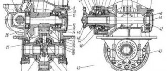
The longitudinal movements of the constant velocity joint are limited by thrust washers, one of which is installed in the ball joint, and the other in the axle. Gearbox of the front and rear axle of the GAZ-66 car. The design of the gearbox of the front and rear axle of the GAZ-66 is shown in Fig. 2. Adjustment of the preload of bevel bearings 6 and 16 of the drive gear of the gearbox is carried out by ring 15. Boring of the sockets in the crankcase and covers 24 of the differential bearings, as well as threading, is done as an assembly, therefore, after disassembling, the covers must be put in their original places, which is ensured by the presence of identical markings on each side of the crankcase and the mating bearing cap. The preload of the axle differential bearings is regulated by nuts 20. The same nuts regulate the position of the driven gear, that is, the amount of lateral clearance, as well as the size and location of the contact patch in the gear mesh.
Fig.2. Reducer of the front and rear axle GAZ-66 1—oil receiving tube; 2—upper channel; 3—lower channel; 4—stop screw; 5—adjusting shims; 6, 16 and 29—taper bearings; 7—cover; 8—nut; 9—drive gear; 10—flange; 11—cuff; 12 - oil removal ring; 13 and 31—bolts; 14 - coupling; 15—adjusting ring; 17 — filler plug; 18—roller bearing; 19—crankcase; 20—nut; 21—axle shaft; 22—differential cup; 23—locking plate; 24—cover; 25—rusk; 26—driven gear; 27—outer sprocket; 28—separator; 30—internal sprocket The gearbox differential of the GAZ-66 axles is cam-type, with twenty-four radial cotters 25 installed in the separator holes in two rows in a checkerboard pattern.
The outer differential sprocket has six cams evenly spaced around its circumference, and the inner sprocket has two rows of cams (six each), arranged in a checkerboard pattern. The main gear and gearbox differential are installed in a separate housing 19, which is freely inserted into the hole in the bridge beam and secured with bolts 31. To ensure a forced supply of lubricant to the drive gear bearings of the front and rear axles, an oil receiving tube 1 is installed in the gearbox housing, which is in contact with the driven gear , collects the oil carried away by it.
From tube 1, through the upper channel 2, oil is supplied to the bearings, and discharged through the lower channel 3. The gearboxes of the GAZ-66 front and rear axles are distinguished by different oil removal rings installed on the splines of the drive gear.
The front axle ring is marked P, the rear axle ring is not marked. To distinguish the gearboxes, there is a P marking on the flange of the drive gear of the front axle (there is no marking on the flange of the drive gear of the rear axle).
To prevent pressure build-up inside the crankcase when heated during operation, a breather is installed in the crankcase. Adjusting the parts of the drive axles of the GAZ-66 car The bearings of the drive axles of the car, the lateral clearance and the contact in the gear mesh are adjusted at the factory and, as a rule, do not require adjustments in operation.
Their adjustment is necessary after replacing parts or when there is significant wear on the bearings. The increased lateral clearance in the meshing of the gears of the gearbox of the front and rear axles of the GAZ-66, resulting from wear of the teeth, cannot be reduced by adjustment, since such an adjustment will lead to a violation of the relative position of the worn-in surfaces of the teeth.
As a result, noise increases or teeth breakage occurs. In operation, changing the position of adjusting screw 4 is not recommended. Adjustment of the bearings of the drive axles is necessary only if the nut is loosened. To do this, adjusting screw 4 must be screwed in completely, then unscrewed 1/6 of a turn and secured with a nut.
The detected play in the tapered bearings should be eliminated, but the position of the gears that have worked together should not be disturbed. When carrying out the bearings of the GAZ-66 drive axles, you should know that locking the bolts of the differential bearing caps and the locking plate of the differential bearing nuts can be done using sealant.
The bolts must be lubricated to 3/4 of the threaded length. You can also lock the bolts with 1.6x400 mm cotter pin wire. When cottering the differential bearing cap bolts, the cotter wire must pass through the locking plate bolt.
If it is difficult to pin a bolt with one hole, it must be tightened in the direction of increasing the tightening torque. Cottering should be done in such a way that the tension when twisting the wire creates a torque in the direction of tightening the bolts. Adjusting the bearings of the drive gear of the GAZ-66 bridge reducer The bearings of the drive gear of the GAZ-66 bridge reducer should be adjusted if the axial play of the gear exceeds 0.03 mm.
The backlash should be checked using an indicator device by moving the drive gear from one extreme position to another, and in the absence of a device, by rocking the flange by hand. If there is play in the drive gear of the axle reducer in the tapered bearings, the bearings must be adjusted. Drain the oil from the axle housing. Disconnect the rear end of the propeller shaft. Remove the axle shafts. Unscrew the gearbox housing mounting bolts. Remove the gearbox. Unscrew the driven gear stop screw so that the end of the stop does not protrude above the end of the boss in the crankcase. Remove the oil pickup pipe. Unlock and unscrew the differential bearing nuts. Before unscrewing the nuts, note their position relative to the differential bearing caps by making marks on the caps and nuts. Remove the GAZ-66 differential bearing caps. Move the differential towards the driven gear and remove it. Unscrew the coupling mounting bolts and remove the coupling.
Check, without disassembling the coupling, whether the thickness of the adjusting ring installed on the bearings is sufficient. To do this, clamp the coupling flange in a vice, and unfasten the nut securing the propeller shaft flange and tighten it until it stops.
If the thickness of the adjusting ring exceeds the required one, then tightening the nut will not lead to noticeable resistance when the drive gear rotates in the bearings. Unscrew the nut securing the propeller shaft flange, remove the flange, oil seal cover and the inner ring with the rollers of the outer bearing. Reduce the thickness of the adjusting ring by grinding until the axial play of the drive gear of the axle reducer is eliminated and a preload of the bearings is created (the reduction in the thickness of the ring should be equal to the sum of the axial play of the gear measured by the indicator and the value of 0.05 mm of preload). Reassemble the coupling in the vice in reverse order and tighten the nut until it stops. When tightening the nut, it is necessary to rotate the flange so that the bearing rollers take the correct position in the cages. Upon completion of adjustment of the GAZ-66 gearbox, the nut must be tightened to capacity. You cannot even turn it back a little to align the hole for the cotter pin with the slot of the nut. If the tightening is insufficient, the inner ring of the bearing may screw in, the adjusting ring may wear out, and, as a result, a dangerous increase in the axial play of the drive gear may occur. Replace the coupling with the oil seal cover and tighten the bolts evenly, having previously lubricated them with Litol lubricant. Assemble the main gear, and tighten the differential bearing nuts to the position marked with the marks. To correctly install the stop of the driven gear of the gearbox of GAZ-66 axles, you need to tighten the stop screw all the way, then unscrew it 1/6 of a turn and lock it with a nut. Install the oil pickup pipe. Put the gearbox in place, having previously lubricated the fastening bolts with Litol-24 grease, connect the flanges of the propeller shaft and the drive gear, and install the axle shafts. Fill the axle housing with oil to the level of the inspection hole. Adjusting the hub bearings of the front axle GAZ-66 When adjusting the hub bearings of the front axle, you need to unscrew the nuts and remove the step, the protective casing, the air supply tube to the tire and the drive flange. Unscrew the outer nut, remove the lock washer, unscrew the inner nut and check that the wheel rotates freely. If it is difficult to rotate the wheel, eliminate the cause (brake pads catching, oil seal sticking, etc.). Tighten the inner nut with a wrench 350-400 mm long by hand until the wheel rotates tightly on the bearings.
In this case, it is necessary to rotate the wheel to correctly position the rollers on the bearing ring raceways. Unscrew the inner nut. Install the lock washer and ensure that the lock pin fits into one of the slots in the washer.
If the pin does not fit into the slot, turn the nut one way or the other so that the pin fits into the nearest slot in the lock washer. Screw and tighten the outer nut. Check the adjustment of the hub bearings of the GAZ-66 front axle - the wheel should rotate without noticeable axial movement and rolling.
Install and secure the flange, air supply tube and protective casing, install the step and tighten the nuts securing the drive flange. Lower the wheel. The adjustment of the front axle hub bearings should be checked based on the degree of heating of the wheel hub during the test run. Strong heating of the hub is not permissible and must be eliminated by repeated adjustment. Adjusting the hub bearings of the GAZ-66 rear axle When adjusting the hub bearings of the GAZ-66 rear axle, remove the protective casing and the air supply tube to the tire, unscrew the nuts and remove the axle shaft 14 (Fig. 3).
Unscrew the outer nut 4, remove the lock washer 5, unscrew the inner nut 6 and check whether the wheel rotates freely. If it is difficult to rotate the wheel, eliminate the cause (brake pads catching, oil seal sticking, etc.).
Rice. 3. Rear hub and wheel GAZ-66 P—cavity; 1—trunnion; 2—bolt puller; 3—flange cover; 4 and 6—bearing nuts; 5—lock washer; 7—hub; 8—air valve; 9—wheel; 10—brake drum; 11 - bypass valve; 12 and 15 — oil seals; 13—bridge beam; 14—axle shaft Tighten the inner nut with a wrench 350–400 mm long by hand until the wheel rotates tightly on the bearings. In this case, it is necessary to rotate the wheel to correctly position the rollers on the bearing ring raceways. Unscrew the inner nut 6. Install the lock washer 5 and make sure that the lock pin fits into one of the slots in the washer.
If the pin does not fit into the slot, turn the nut one way or the other so that the pin fits into the nearest slot in the lock washer. Screw and tighten the outer nut 4. Check the adjustment of the rear axle hub bearings - the wheel should rotate without noticeable axial movement and rolling.
Insert and secure axle shaft 14, air supply tube and protective casing. Lower the wheel. Check the adjustment of the rear axle hub bearings based on the degree of heating of the wheel hub during a test run. Strong heating of the hub is unacceptable and must be eliminated by repeated adjustment.
_________________________________________________________________________________________
- GAZ-3307 clutch maintenance
- Steering system GAZ-3307
- Gearbox parts for GAZ-3307
- Maintenance of the rear axle GAZ-3307
- Maintenance of the fuel system of the D-245 diesel engine
- Clutch GAZ-3309 with a diesel engine
- Operations for disassembling the GAZ-3309 gearbox
- GAZ-3309 front axle service
- Repair of cardan shafts of GAZ-3309 cars
_________________________________________________________________________________________
_________________________________________________________________________________________
- Operations for assembling basic components of the ZIL-130 engine
- Service and repair operations for the ZIL-130 gearbox
- Maintenance and repair of ZIL-130 clutch
- Repair and adjustment of the rear axle ZIL-130
_________________________________________________________________________________________
- KAMAZ-4310, 43118, 43114
- KAMAZ-5320, 55111, 53212, 5511, 55102
- KAMAZ-65115, 6520, 65117
- KAMAZ-4308
- Engine KAMAZ-740
_________________________________________________________________________________________
- Parts of the cylinder block and head of the YaMZ-236 engine
- Service maintenance of the YaMZ-236 piston group and crankshaft
- Diagnostics and technical adjustments of the YaMZ-236 engine
- Design and adjustment of fuel injection pump and injectors of the YaMZ-236 engine
- Cylinder block and piston YaMZ-238
- Components of the YaMZ-238 diesel fuel supply system
- Design and adjustment of the fuel injection pump of the YaMZ-238 diesel engine
- Technical design of the YaMZ-239 gearbox
_________________________________________________________________________________________
- Components of the front axle and steering rods of the Maz-5516, 5440
- Steering system of Maz-5516, 5440 cars
- Clutch and gearbox parts Maz-5516, 5440
- Maintenance of drive axles of MAZ-5516, 5440 vehicles
- Power steering for Maz-5551, 5335 cars
- Maintenance of cardan transmission of Maz-5551, 5335 cars
- Maintenance and adjustment of clutch MAZ-5551, 5335
- Repair and service of the rear axle of MAZ-5551, 5335 cars
_________________________________________________________________________________________
- Gearbox Ural-4320
- Construction and adjustment of Ural-4320 bridges
- Maintenance of transfer case Ural-4320
- Steering components Ural-4320
_________________________________________________________________________________________
- Servicing the KRAZ-255, 260 gearbox
- Steering mechanism and power steering Kraz-255, 260
- Adjustments and repairs of the power steering cylinder and steering rods of the Kraz car
- Drive axle components and drive shafts Kraz-255, 260
Transfer case malfunctions
The transfer case is one of the most loaded mechanisms in the all-wheel drive system. The service life of the box depends on both operating conditions and the quality of vehicle maintenance. Malfunctions can be identified by the following signs:
- difficulty turning on or off control levers;
- extraneous noise and vibration when the modes are on;
- traces of lubricant leaks on the transfer case housing.
Typically, bearings, drive gear teeth, and forks or rods wear out significantly. The cause of the breakdown may also lie in insufficient quality or low oil level in the transfer case housing.
Again about replacing the axle shaft seal
I’ve been reading the conference on GAZ for a long time, but I decided to write for the first time, because... there was a real question. Like many others, the rear left axle shaft seal leaked. It’s clear what to do... change. I myself had never performed this operation, so I rushed to read the manual and the conf. After a short ordeal I have the following information:
According to the manual: 1. Remove 2. Knock off the bushing 3. Replace it 4. Place the new bushing on the “hot” one
By conference This is where I didn’t understand anything. I got the feeling that the oil seal can be changed without all these troubles with “hot” in just 15 minutes, without removing the bearing. How to do it? If it is possible to answer, I will be very grateful for the instruction, because... I turn to services and TMP as a last resort.
PS If it’s still a hot one, you’ll have to drive up to the local goblins in town, remove everything yourself, pay them for heating and fitting a new bushing, and assemble everything yourself—cheaper than at a service center, but still. One of the extreme and completely unpleasant options is to buy a new axle shaft (if the work + oil seal + bearing will cost approximately the same as a new axle shaft), which is not very desirable, because I always have time to buy a crooked axle shaft.
I'm waiting for your answers. Thank you!
Re: That's it, the issue is resolved. Once in the bridge, then the operating algorithm is clear. As far as I understand, there is also a metal plate on the bridge. So:
1. We remove everything, take out the axle shaft. 2. We take out the metal plate (ala washer) 3. We pick out the old oil seal and press in two new ones. 4. Lubricate everything and put it back. 5. At the same time, we change the pads and clean the drum (because it’s in oil)..)))
Source