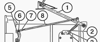
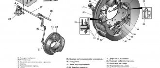
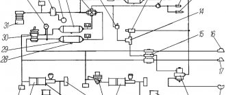
1-compressor; 2-pressure gauge; 3-receiver (compressed air tanks); 4-rear brake chambers; 5.6- tap for connecting to a trailer; 7-pneumatic line; 8-main brake valve; 9-front brake chambers.
The service brake is a drum type, with two internal shoes, installed on all wheels of the ZIL-130 vehicle. The service brake drive is pneumatic, providing the ability to automatically (synchronously with the vehicle brakes) activate the trailer brakes, if the latter is equipped with brakes with a pneumatic single-line drive.
When you press the pedal, the brake valve allows compressed air from the cylinders to enter the brake chambers. Under air pressure, the brake chamber rods move, turning the expansion knuckles, which press the pads against the brake drums. When the pedal is released, the brake valve closes the air outlet from the cylinders and releases air from the brake chambers into the atmosphere.
Adjusting the service brake ZIL-130
Adjustment of the ZIL-130 service brake can be complete or partial. The brakes should be cold when adjusting. Full adjustment is made only after disassembling and repairing the brakes or breaking the concentricity of the working surfaces of the brake pads and drums as a result of loosening the pad axes.
Full adjustment must be made in the following order:
- Loosen the nuts securing the pad axles and bring the eccentrics closer together, turning the axes with their marks facing each other. The marks are placed on the outer ends of the axles protruding above the nuts. Loosen the nuts of the bolts securing the expansion knuckle bracket, and on the rear axle also loosen the bolts securing the expansion knuckle bracket to the axle housing, having first removed the shields.
- Apply compressed air to the brake chamber at a pressure of 1-1.5 kgf/cm2 (100-150 kPa), pressing the brake pedal when there is air in the system or using compressed air from a stationary installation. If there is no compressed air, remove the brake chamber rod pin and, pressing the adjusting lever towards the stroke of the brake chamber rod when braking, press the shoes against the brake drum. By turning the eccentrics in one direction or the other, center the pads, ensuring their tight fit to the brake drum. Check the fit of the pads to the drum with a feeler gauge through the window in the front brake drum at a distance of 20-30 mm from the outer ends of the linings. On rear brakes, it is more convenient to check the fit from the side of the axle gearbox. The 0.1 mm feeler gauge should not extend across the entire width of the trim.
- Without stopping the supply of compressed air to the brake chamber, and in the absence of compressed air, without releasing the adjustment lever and holding the axles of the pads from turning, securely tighten the axle nuts and the nuts of the bolts securing the expansion knuckle bracket to the brake support disk. At the rear axle brakes, tighten the bolts securing the expansion knuckle brackets to the crankcase and the bolts securing the expansion knuckle support to the caliper.
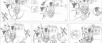
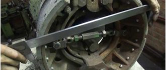
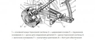
- Stop the supply of compressed air, and if there is no compressed air, release the adjusting lever and attach the brake chamber rod. The photo shows an adjusting lever or, in the jargon, a “ratchet”, and below is a diagram of the connection of the adjusting lever with the brake chamber rod, shows the principle of the worm shaft of this mechanism and shows the connection with the expansion knuckle.
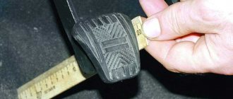
- Rotate the worm axis of the adjusting lever so that the stroke of the brake chamber rod is within 15-25 mm for the front brakes and 20-30 mm for the rear brakes. Make sure that the brake chamber rods move quickly when turning the air supply on and off.
- Check how the drums rotate when braked. They should rotate evenly and freely without touching the pads. Then install guards on the rear brakes.
Partial adjustment is made to reduce the gap between the pads and the drum. The presence of large gaps, which require partial adjustment, is detected by an increase in the stroke of the brake chamber rod, which should not exceed 35 mm for the front brakes and 40 mm for the rear brakes.
If the rod stroke is large, partial adjustment is required.
Partial adjustment is performed only by rotating the worm axes of the adjusting levers, the same as with full adjustment. During partial adjustment, you should not loosen the nuts of the shoe axles and change the installation of the axles, as this may lead to a violation of the tight fit of the shoes to the drum during braking.
If the installation of the axles is changed, a full adjustment must be made.
When making adjustments, it is necessary to set the minimum stroke of the brake chamber rods. To obtain equal braking efficiency for the right and left wheels, you should strive to ensure that the strokes of the rods of the right and left chambers are the same.
Westinghouse air brake is the name given to brake actuator systems that use compressed air to operate.
The first reliable (automatic) air brake system was patented by George Westinghouse on March 5, 1872. Westinghouse's invention was truly revolutionary for railroads, providing reliable braking, which, in turn, expanded the range of speeds at which trains of those years could travel. Westinghouse also proposed many additions to his invention, making it possible to use it in a wide variety of automatic braking systems.
In the simplest air brake system, called a direct-acting system (or direct-acting brake), compressed air presses against a piston in a cylinder. The piston is connected to the brake pad, which rubs against the wheel, causing it to stop.
The air brake system is used on trucks, buses, on domestically produced vehicles such as ZIL, Ural, KAMAZ, KrAZ, on foreign-made vehicles, this brake system is more suitable for trucks because it is more reliable than other braking systems.
The goals and objectives of writing the work: to provide an explanation of the ZIL-130 brake system, the design and repair of the ZIL-130 brake system and its maintenance, as well as to explain the technological process of disassembling and assembling the parking brake of a ZIL-130 car.
Principle of operation
Made to control the actuators of the working brake system of a car, ZIL-130, as well as to activate the control valves of the trailer brake system.
The brake valve is mounted on a bracket attached to the frame side member. The air exits the tap downward through terminal 5.
The brake valve has two independent sections arranged in series. Terminals 1 and 2 of the valve are connected to the receivers of the separate drives of the service brake system.
two-piece brake valve
The force from the brake valve lever is transmitted through the rubber elastic element 31 to the upper piston 30. Moving down, the piston closes the outlet hole of the valve 29 and then lifts it off the seat. Through output 3, compressed air enters the brake chambers of the rear wheels until the force of pressing the lever is balanced by the pressure of compressed air on the piston 30 from below.
Simultaneously with the increase in pressure in outlet 3, compressed air through channel A in the valve body enters cavity B above the large piston 28 of the second section of the brake valve. The piston, which has a large area, moves downward with a slight pressure in the above-piston space and acts on the small piston 15. As the piston moves, the outlet of the valve 17 closes, and then it comes off the seat. Compressed air through port 4 enters the brake chambers of the front axle wheels.
When the pressure in port 4, and consequently in cavity C under pistons 15 and 28, increases, the force acting on the pistons from above is balanced. Thanks to this, a pressure corresponding to the force on the brake valve lever is also established in pin 4 (following action).
Parking brake ZIL-130
The brake system consists of a brake mechanism and a drive. For traffic safety, two brake systems must be installed on each car: the first (main), acting on the wheels, is the working one, and the second, in most cases acting on the secondary shaft of the gearbox, is the parking one.
Parking brake ZIL
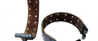
The most widely used wheel brakes are friction shoe brakes. Friction block-disc and band brakes are used primarily as parking brakes.
The shoe brake mechanism of ZIL trucks (Fig. 217) has two internal shoes 14 with friction linings riveted to them. The pads rest on fingers 2. When braking, the pads are moved apart with a fist, and the friction linings are pressed against the inner surface of the drum. The pads are brought to their original position by tension springs. The soft brake pads of the PA3-672 bus and GAZ cars (Fig. 218) are moved apart by the pistons of 2 wheel cylinders.
Parking brake device
Removing the hand brake. To remove the hand brake from the gearbox of a ZIL-431410 car with a single-circuit brake drive, you need to disconnect the propeller shaft flange, unscrew the nut securing the flange on the driven shaft of the gearbox, remove the flat washer and the flange assembly with the drum using a puller.
Handbrake ZIL-130
Fig.12-17. Vehicle transmission brake:
1 friction lining; 2 - drum; Z - bracket; 4 - cuff; 5 and 14 - respectively potassium and large tension springs of the pads; 6 and 13 pads: 7 - pad axis; 8 — flange fastening nut; 9 - screw; 10 — flange of the secondary shaft of the gearbox; 11 — adjusting bolt; 12 — limit washer; 15 — block block; 16 — expanding fist: 17 — shield; 18 — adjustment lever; 19 — fork: 20 — drive rod; 21 — brake valve rod eye; 22 — rod finger; 23 - nut; 24 - lever plate; 25 — gear sector; 26 — spacer sleeve; 27 - locking latch; 28 — locking rod; 29 — lever; 30 – locking latch pull handle.
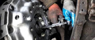
Removing the springs
Figure 12-18 Method for removing the parking brake shoe tension springs.
Disconnect the pad springs using pliers (Fig. 12-18), unscrew and remove the two pad mounting bolts with two spacers and two flat washers and remove the brake pads.
Unscrew the bracket mounting bots on the gearbox housing and remove the bolts and washers.
ADJUSTING THE TAP
We apply pressure to terminals 1 and 2 and try to move the lever all the way and back several times and see with what difference the air comes out at terminals 3 and 4 and with adjusting bolt 1 we adjust the air supply so that it comes out evenly to the front and rear axles. This way we will adjust the order in which the brakes are applied.
drive installation
connection diagram
WATCH THE VIDEO
Source
Wheel brake of the front wheel of ZIL trucks
Rice. 217. Wheel brake of the front wheel of ZIL trucks and LAZ and LIAZ-677 buses:
PAZ wheel brake
Rice. 218. Front wheel brake of the PA3-672 bus and GAZ-53A car:
1 — protective cap; 2 —— wheel cylinder; 3—support disk; 4—coupling spring; 5—guide bracket; 6—block; 7 — friction lining of the block; 8—adjusting eccentric bolt; 9— washer; 10—eccentric spring; 11—adjusting eccentric; 12 - support ring plate; 13 — support pin eccentric; 14—support finger; !5—nut; spring washer.
When brake drums and friction linings wear out, the gap between them increases, causing the car's braking distance to lengthen. The size of the gap is adjusted by turning the expansion fist or eccentric 11 (see Fig. 218) using a worm mechanism 10, 11 and 12 (see Fig. 217), which changes the distance between the column b and the drum. 7
When the friction linings are re-riveted, there is significant wear, or when the pads are not installed properly due to weakening of the support pins, the position of the pads is changed by turning the support pins, the necks of which are eccentric.
When braking, fluid pressure moves piston 3 to the right, which presses the shoe against the brake drum. If the gap between the friction lining and the brake drum has increased due to wear, then the piston 3 drags the spring ring 2 through the threaded connection, overcoming the tension force. Spring ring 2 moves in the cylinder by the amount of wear.
When the driver stops pressing the brake pedal, the pressure in the cylinder drops, the tension springs tighten the brake pads and piston 3 moves along the cylinder to the left. However, piston 3 can only move by the amount of play in the threaded connection with the spring ring 2, since the force of the tension springs of the pads is 20 kg, and the tension force of the ring is more than 2 times greater, and it will not be able to move to the left. Thus, the return stroke of the piston, and therefore the pad, is limited.
A drum-type parking brake (Fig. 221) is installed on GAZ vehicles. PAZ-672, ZIL-1ZO, 3IL-164A, LAZ buses and Ural cars. When the lever 2 is pulled back, the expansion fist 8 moves the shoes towards the drum 5. When released, the tension springs 6 and 6 pull the shoes away from the drum.
For MAZ-500 vehicles, a drum-type manual parking brake is mounted on the rear axle of the vehicle. This arrangement of the brake allows it to be used in emergency situations, even if the driveshaft breaks down.
LIAZ brake drive
On the LiAZ-b77 car, the handbrake has a mechanical drive and acts on the rear wheels (Fig. 222), which makes it possible to use it as an emergency brake.
Wheel brake drives on domestic cars are hydraulic, pneumatic and pneumohydraulic. To make the driver's work easier, some cars use amplifiers. The hand brake is mechanical;
The hydraulic brake drive has a number of advantages: pressure is transferred to all wheel brakes evenly and smoothly, and the drive operates quickly.
The hydraulic drive of passenger cars, trucks GAZ-BZA, GAZ-66, PAZ buses consists of a master brake cylinder, wheel brake cylinders and lines.
Parking brake
Rice. 221. Handbrake for LAZ buses and. ZIL cars:
1—threaded rod fork; 2—handbrake lever; Z—sector: 4—brake adjustment lever; 5 — brake drum; 6 — tension spring; 7—brake pad; Z—opening fist.
The main brake cylinder (Fig. 223) is cast together with the brake fluid reservoir and communicates with it through two holes. When you press the brake pedal, the cuff 3 closes holes B and C, the liquid is squeezed out through the bypass valve 8 into the line and enters the wheel brake cylinders, the pistons of which press the brake pads to the drums
Main cylinder PAZ-GAZ
Fig. 223 Main cylinder of the hydraulic brake drive of PAZ buses and GAZ cars:
1- retaining ring; 2 - thrust washer; 3- cuff; 4-plate valve; 5- rubber cuff; 6- bypass valve spring; 7- check valve; 8- bypass valve; 9- threaded plug; 10- housing cover; 11- building; 12- fitting; 13- spring; 14- piston; 15- cover; 16- pusher; 17- locknut; 18- thrust; 19- pedal; 20-tension spring.
WATCH THE VIDEO