Category: KAMAZ
- When to do repair work
- Stages of work First stage - adjusting the pedal
- The second stage is debugging the coupling
- The third stage is adjusting the pusher stroke
KamAZ is a very reliable vehicle that is used in many areas, mainly for cargo transportation. But, like any other equipment, even it can break down from time to time. The clutch system is subjected to especially heavy loads here. If you do not monitor its condition, it may fail. How to adjust the clutch on a KamAZ to improve the performance of the mechanism?
Do-it-yourself KAMAZ clutch replacement
To replace the clutch yourself, you will need help removing the gearbox.
Work order:
- Unscrew the fastening nuts, remove the cardan, pneumatic hydraulic booster, and release the starter from the mounting.
- Remove the pipes for the reduction gear, as well as the gear lever.
- Take a jack.
- Place a jack under the engine sump and lift the engine.
- Remove the rear cross member and the spacer rod.
- Release the bracket from the fastening.
- Secure the hoist and tighten it.
- Remove the engine side mounts. Unscrew the gearbox fasteners to the engine.
- Using a hoist, move the gearbox away from the engine until the input shaft comes out, then remove it.
Maintenance
In addition to settings, the clutch of KamAZ vehicles requires regular maintenance, since this significantly increases the service life and reliability of the mechanism on all KamAZ brands.
Using model 53215 as an example, maintenance consists of the following main points:
- Checking the tightness of the amplifier mounting bolts in the clutch drive circuit.
- Monitoring the tightness of hydraulic lines. There should be no oil stains on them.
- General check of serviceability of pedal assembly parts. All elements must be in good condition and not have large gaps in the connections.
- Checking the presence of lubricant in the clutch bearing and fork connection bushing. To supply oil in the clutch housing there are three points equipped with grease nipples. Oil is injected into them using a syringe.
- Draining condensate from the CCGT housing.
- Checking the fluid level in the amplifier reservoir.
When is clutch replacement required?
If all the work performed does not lead to the restoration of the clutch mechanism, then this becomes one of the signals to replace it.
Other signs of critical wear of structural elements are:
- sudden turning on of the disks, resulting in a hard jerk of the car;
- difficulty engaging all gears, accompanied by a characteristic crash;
- sluggish acceleration of the car, while the engine speed clearly does not correspond to the selected gear and speed;
- smell of burning pads when driving.
If such problems occur, it is necessary to stop moving as soon as possible and repair the mechanism. Continued operation of the vehicle with faulty or burnt-out clutch discs will lead to failure of the gearbox.
How to remove the clutch basket
Repairing the KAMAZ clutch basket with your own hands involves removing it. It includes the flywheel, pressure plate and protective cover. The driven part is made of steel discs that dampen vibrations.
Repairing the KAMAZ clutch basket requires its preliminary removal. To do this, you need to screw 4 bolts into the pressure disk and press the disk into the casing. Using pliers, you should carefully press out the antennae on the lock washers, then remove the elements with which the casing is attached to the flywheel, then remove the discs and clutch casing in turn.
Before repairing the KAMAZ clutch and removing the clutch basket, it is necessary to use a core to mark the location of the basket and the flywheel.
Design features of the clutch
The bulk of KamAZ trucks use a double-disc clutch with a radial arrangement of power springs. To operate the mechanism, a hydraulic drive with a pneumatic amplifier is used. Thanks to this design, the force required to press the clutch pedal is significantly reduced. During the operation of KamAZ, wear occurs on the clutch discs, which must be compensated for by adjustment. Correct adjustment of the mechanism ensures the fuel consumption declared by the factory and confident acceleration of an empty or loaded vehicle.
Removing the clutch discs
Replacing a KAMAZ clutch disc requires its removal. KAMAZ has a friction 2-disc clutch, pressure springs and a device for automatically bringing the middle drive disk to the middle position.
When removing the flywheel, it is necessary to take into account the specifics of its design: the drive middle disk is installed in the grooves of the flywheel, which are located around the circumference of this disk. To ensure heat dissipation in the clutch and its ventilation, the disc in its “body” has holes that separate the ribs (spikes). These cleats have a lever that adjusts the position of the driving middle disc. Both the pressure and middle drive disks are located on spikes in grooves located in the flywheel.
The other side of the disk has protrusions that are designed for pressure springs. You should remember the order in which they are placed. The driven disk includes a hub, a spring, a rivet, linings, and a torque vibration damper. The hub with the disk does not have a rigid connection, there are only 8 springs. The space between the driven and driving disks is where the release springs are located, as well as the intermediate disk adjusting bolt.
Clutch of KamAZ-4310 and URAL-4320 vehicles
Military Encyclopedia - historical and archival military-patriotic portal
home☆Soviet military encyclopedia☆military equipment☆military science☆military review☆history of weapons☆forum
military equipment ☆ articles on the VAT device ☆
On KamAZ-4310 and Ural-4320 vehicles, a friction dry double-disc clutch with a peripheral arrangement of springs is installed. The clutches of both cars are the same, their parts are interchangeable, the difference is in the drive. On the KamAZ-4310 vehicle the clutch drive is hydraulic with a pneumatic booster, on the URAL-4320 vehicle the clutch drive is mechanical.
The clutch is called frictional and dry because the transmission of torque in it is carried out due to the friction forces between the disks, the surface of which must be dry; the disks are compressed by springs located along the periphery of the disks; The torque is perceived by two driven disks.
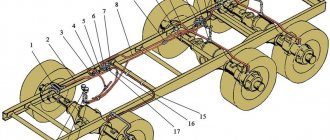
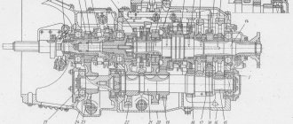
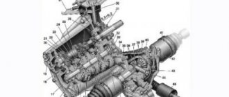
Rice. 96. Clutch mechanism for KamAZ-4310 and URAL-4320 vehicles : 1 - flywheel; 2 — middle disk; 3 — driven disks; 4 - crankcase; 5 — pressure disk; 6 - casing; 7 — support fork; 8 — adjusting nut; 9 — lock washer; 10 - locking plate; 11 — pull lever; 12 — lubricant supply hose to the clutch release clutch; 13 — clutch release; 14 — clutch release fork; 15 - thrust ring; 16 – fork shaft; 17 — pressure spring.
The clutch parts are located in an aluminum housing 4 (Fig. 96), bolted to the flywheel housing. On top of the crankcase there is a hatch for inspection of clutch parts; the hatch is closed with a lid. The bottom of the crankcase has two hatches, also closed with lids. A crowbar is inserted through the front (small) hatch to rotate the flywheel. The rear hatch cover has a threaded hole for grease drainage; Before crossing the ford, this hole is closed with a plug screwed into the blind boss of the lid. The clutch consists of driving and driven parts, a pressure device and a release mechanism with a drive.
The leading parts include flywheel 1, casing 6, pressure disc 5 and middle disc 2. The stamped casing is installed on flywheel 1 using mounting bushings and secured to it with twelve bolts. The pressure and middle disks each have four protrusions on their outer surfaces that fit into the grooves of the flywheel. Torque is transmitted through the protrusions from the flywheel to the discs; This installation of the disks allows them to move axially when the clutch is disengaged.
The protrusions of the middle disc house a lever mechanism that automatically adjusts the position of the disc when the clutch is disengaged. This mechanism consists of a lever with an axis and a spring. The lever axis is screwed into the hole in the protrusion and secured against turning with a rivet. The lever is placed loosely on the axle and is pressed by a spring, one end of which rests against the plane of the groove, the other against the hole in the lever. The spring constantly strives to rotate the lever around the axis, while one end of the lever rests against a cracker pressed into the flywheel, and the other against a specially hardened place on the pressure disk. When the clutch is released, the lever mechanism sets the disc to the middle position and ensures clean disengagement.
The driven parts include two driven disk assemblies 3, installed on the splines of the gearbox drive shaft. Each driven disc consists of a steel split disc, two friction linings, a hub and a torsional vibration damper. Cutouts on the steel disk increase its elasticity and protect it from warping when heated. The friction linings are made of an asbestos composition and riveted to the steel disc with non-ferrous metal rivets. The steel split disk, together with the friction linings, is connected to its hub through a torsional vibration damper.
Torsional vibrations occur on the crankshaft and transmission shafts from uneven engine operation, when the clutch is abruptly engaged, or when the vehicle moves over uneven surfaces.
The torsional vibration damper consists of two rings with friction linings, two disks, eight cylindrical springs and two disc springs that press the damper disks against the friction rings. The transmission of torque through the cylindrical springs of the damper prevents the possibility of high-frequency vibrations occurring on the shafts; low-frequency vibrations that may arise in this case are damped due to friction between the discs and the friction linings of the damper rings.
The pressure device includes twelve cylindrical springs 17 located between the casing and the pressure disk; A washer and a heat-insulating ring are placed under each spring on the pressure plate side. The total spring force is 10.5…12.0 kN.
The release mechanism includes four levers 11 with a thrust ring 15, a support fork 7 with a nut 8, a clutch 13 with an angular contact bearing, a release fork 14 with a shaft 16. Each lever is mounted on a needle bearing in the support fork, the outer end
The lever is attached to the lugs of the pressure plate through a needle bearing. The nut 8 of the support fork 7 has a conical flange and rests on a plate 10 of a wavy profile, which, together with the support lock washer 9, is attached to the casing b with two bolts. A thrust ring is pressed against the inner ends of the levers 11 using springs and hinges. Clutch 13 is pulled to the rear position by two springs.
Clutch operation. In the on position, the driven disks 5 are clamped between the flywheel, the middle disk and the pressure disk by the force of the pressure springs. Between the thrust ring 15 and the release clutch bearing, a gap of 3.2...4.0 mm is established. Torque is transmitted from the flywheel through the protrusions to the middle and pressure plates. From the working surfaces of the flywheel, middle and pressure disks, due to friction forces, torque is transmitted to the friction linings of the driven disks and then through the torsional vibration dampers to the drive shaft of the gearbox. All clutch parts, except the release clutch, rotate as one unit.
When the clutch is disengaged, the force from the drive is transmitted to the clutch 13, which moves forward and after selecting the gap, the clutch bearing presses the thrust ring 15 and the levers 11 associated with it. The latter rotate relative to the support fork 7, while the outer ends of the levers move the pressure plate back. The middle disc is self-aligned between the flywheel and the pressure plate using a lever mechanism. A gap forms between the rubbing surfaces of the clutch, and the transmission of torque from the driving parts to the driven parts stops.
When the clutch is engaged, clutch 13 returns back with the force of its springs, the pressure springs again press the drive and driven disks against the flywheel, and torque transmission resumes. Since all the rubbing surfaces do not come into contact with each other instantly, the increase in torque transmitted through the clutch occurs with some slowdown, which ensures smooth engagement of the clutch. This is also facilitated by the smooth release of the clutch pedal.
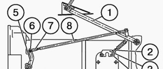
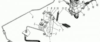
Rice. 97. Clutch drive of a KAMAZ-4310 vehicle : 1 - pedal; 2 - lower stop; 3 — bracket; 4 - upper stop; 5 — lever; 6 - eccentric pin; 7 — piston pusher; 8 - spring; 9 — main cylinder; 10, 14 - pipelines; 11 — pneumohydraulic booster; 12 - plug; 13 - bypass valve; 15 - protective: cylinder; 16 — piston pusher; 17 — adjusting nut; 18 — compensation tank
If the transmission is overloaded, the drive disks slip relative to the driven ones, which protects the engine crankshaft and transmission parts from twisting and damage.
The clutch drive of the KamAZ-4310 vehicle is hydraulic with a pneumatic amplifier. The drive consists of pedal 1 (Fig. 97) with spring 8, main cylinder 9, pneumatic-hydraulic booster 11, pipelines and hoses. The clutch pedal is installed on the axis of bracket 3, mounted on the front panel of the cab. The pedal rotates relative to its axis on two metal-plastic bushings. The 5th axis lever is connected to the master cylinder pusher using an eccentric pin b installed in two nylon bushings.
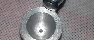
Rice. 98. Main cylinder : 1 - pusher; 2 - body; 3 - piston; 4 — tank body; 5- cork barrel; A - gap.
The clutch master cylinder consists of a housing 2 (Fig. 98) with a plug, a piston 3 with a rubber collar, a pusher 1 and a spring.
The internal space in the housing is divided by a partition into two cavities - working and compensation. A piston with a cuff and a spring are installed in the working cavity. The compensation cavity is designed to store a supply of working fluid. The upper part of the case is covered with a rubber boot.
When the clutch pedal is released, pusher 1 is in the upper position. Piston 3 is pressed against the housing partition by spring force. A gap is established between the pusher and the piston and both cavities communicate with each other through a hole in the piston.
When you press the pedal, the pusher selects a gap, closes the hole in the piston and moves it; pressure is created in front of the piston, which is transmitted through pipelines to the pneumatic amplifier.
The pedal stroke at which the clearance in the clutch drive is selected is called free play. The pedal stroke after selecting the gaps all the way is the working stroke. Free and working travel form the full travel of the clutch pedal.
The main cylinder is connected by a tube to tank 4, closed with plug 5. The hydraulic drive is filled with GTZh-22M or Neva brake fluid in the amount of 0.28 liters. The normal liquid level in the tank should be no lower than 15...20 mm from the upper edge of the filler neck of the tank.
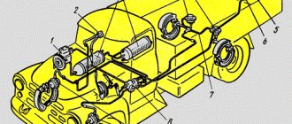
Rice. 99. Pneumohydraulic amplifier of the clutch drive of the KamAZ-4310 vehicle: 1 - spherical nut with locknut; 2 - pusher; 3 — protective cover; 4 - hydraulic piston; 3 — rear body; 5 - combined seal; 7 – follower piston; 8 - bypass valve; 9 - diaphragm; 10 — inlet valve; 11 — exhaust valve; 12 - pneumatic piston; 13 - plug; 14 — front body; A – hole for liquid supply; B - hole for air supply.
The pneumohydraulic booster (Fig. 99) serves to reduce the force on the clutch pedal. It is attached with two bolts to the clutch housing on the right side. Its main parts are: front 14 and rear 5 housings, pneumatic piston 12 with a pusher, cuff and return spring, hydraulic piston 4 with seals, spacer spring and pusher 2; tracking mechanism.
The front body is made of aluminum alloy, the rear body is made of cast iron; Each housing has two borings for installing pistons and follower parts. The housings are connected to each other with bolts.
Pneumatic piston 12 is installed in the front housing and sealed with a rubber cuff. A pusher, manufactured integrally with the hydraulic piston 4, and a return spring rest against the bottom of the piston. The space in front of the Piston is connected by an internal hole in the front housing to the cavity of the valves of the follower mechanism. Plug 13 serves to remove condensate from the cavity of the pneumatic piston.
Hydraulic piston 4 is installed in the lower bore of the rear housing, which acts as a cylinder; The seal of the hydraulic working cavity is ensured by a combined seal 6.
The follower mechanism is designed to change the air pressure in the space in front of the pneumatic piston in proportion to the force on the clutch pedal. This mechanism includes: a piston 7 with a cuff, a rubber diaphragm 9 with an exhaust valve seat, a diaphragm spring, conical inlet 10 and exhaust 11 valves.
Piston 7 moves in the rear housing and rests against the exhaust valve seat. The cavity of the piston 7 of the follower mechanism is connected to the cavity of the hydraulic piston 4 by an internal channel. Diaphragm 9 is clamped by its edges between the front and rear housings by pneumatic amplifiers. The exhaust valve seat 11 is fixed in the center of the diaphragm. The spring presses the diaphragm to its extreme position, the conical inlet and exhaust valves are assembled on a common rod on which the spring is placed. The cavity in front of the diaphragm is connected by a calibrated hole to a channel for supplying air to the pneumatic piston.
The working fluid from the main cylinder enters the hydraulic piston cavity through hole A in the rear housing. Compressed air from the car's pneumatic system is supplied to the pneumatic booster through hole B. Air is released into the atmosphere through a seal located on top of the follower mechanism. Bypass valve 8 serves to release air when pumping the hydraulic drive.
When the clutch pedal is released, the diaphragm of the follower mechanism, together with the exhaust valve seat 11 and piston 7, is moved back (to the left), the exhaust valve is open, the intake valve is closed. The space in front of the pneumatic piston is connected to the atmosphere; pneumatic piston 12 is in the extreme forward position under the action of the spring.
When you press the pedal, the working fluid from the main cylinder enters the cavity in front of the hydraulic piston 4 and through the channel in the rear housing 5 to the piston 7 of the follower mechanism. Piston 7 together with the diaphragm moves forward, exhaust valve 11 closes, and with further movement, inlet valve 10 opens and compressed air enters the cavity in front of the pneumatic piston. The forces created by the pneumatic and hydraulic pistons are summed up and transmitted through pusher 2 to the clutch release fork lever.
At the same time, compressed air enters the cavity in front of the diaphragm, which, as pressure increases, bends back, and the inlet valve closes. When you press the pedal further, a new portion of air will flow to the pneumatic piston. This ensures proportionality between the force on the clutch pedal and the air pressure on the pneumatic piston.
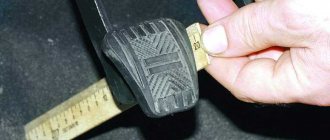
Adjustments of the clutch of the KamAZ-4310 vehicle. The free play of the clutch pedal should be 30-42 mm, which is ensured by the gap between the release pin bearing and the thrust ring of the levers and the gap between the pusher and the master cylinder piston.
The gap between the clutch bearing and the thrust ring is adjusted using spherical nut 1 of the pneumatic booster piston pusher. The size of the gap is judged by the free play of the clutch fork shaft lever, which should be 3.7...6.5 mm. The free play of the lever is checked at a radius of 90 mm. The indicated free play of the lever corresponds to a gap between the bearing and the ring of 3.2 ... 4.0 mm.
The gap between the piston and the master cylinder pusher is adjusted using eccentric pin 6 (see Fig. 97), with which the pusher is attached to lever 5. The pin should be turned so that the movement of the pedal from the top stop until the pusher touches the piston is 6...12 mm .
With a serviceable, pumped and adjusted drive, the full stroke of the pneumatic booster rod should be at least 24 mm, and the full stroke of the pedal should be 185...195 mm.
Rice. 100. Clutch drive of the URAL-4320 car : 1 - pedal; 2 - intermediate shaft; 3.7, 9, 11 — levers; 4. 5 - rods; 5 - servo spring; 6 — pedal shaft; 8 — pedal travel limiter.
The clutch drive of the Ural-4320 car is mechanical. It consists of pedal 1 (Fig. 100) with servo spring 5, four levers 3, 7, 9, 11; two rods 4 and 10, intermediate shaft 2 with bracket. The pedal is fixed to shaft 6 located in the pedal bracket. In the initial position, the pedal rests against limiter 8.
When you press the pedal, rod 4 moves upward, lever 3 with intermediate shaft 2 rotates clockwise, the lower end of the lever moves forward along with rod 10, which turns lever 11, and with it the shaft and fork 14 (see Fig. 96) . The latter acts on the clutch 13 to release the clutch.
When selecting free travel of the pedal, the driver expends some effort to stretch the servo spring 5 (see Fig. 100), which, when making a working stroke, helps the driver disengage the clutch.
Adjusting the cordon of the Ural-4320 car. The free play of the pedal should be 30-40 mm, which corresponds to the free play of the end of the lever 11 of the release fork shaft of 6.1-9.2 mm. The free play is adjusted by changing the length of the rod 10. If the thread of the rod is completely used, it is necessary to move the lever 11 to one slot.
Full pedal travel should be 195 mm, while full lever travel should be 34.6-45.8 mm. The full travel of the pedal is adjusted by turning in or out the limiter adjusting screw 8.
Tags: Kamaz 4310 ☆ car transmission ☆ Ural 4320 ☆ car device ☆
| General information about vehicle transmission and clutch < Prev. | Track. > Clutch of the ZIL-131 car |
Fast delivery of a tow truck to Shchelkovo
In Moscow and Moscow region
- Contacts:
- +7
- around the clock
- seven days a week
© Military Encyclopedia. Map of site.
Assembly of parts and their replacement
Installing and replacing a double-disc clutch on a KAMAZ is a simple process. Common types of damage to the driven and pressure disks are cracks on their surfaces, on the linings, wear of the rings and linings, curvature of the disk, deterioration of the hub fastening, damage to the rivets, and scuffing on the disk surfaces. Replacing used gaskets with new ones requires removing old rivets. Disks that have become unusable also need to be replaced.
Not every car owner knows how to properly install clutch discs on a KAMAZ. There is a certain procedure.
The first of the driven disks is installed with the long end of its hub to the motor, and the second - with the same end to the gearbox. Before tightening the basket, the discs must be balanced.
As the linings on the driven disks wear out, as well as their replacement, the clutch drive should be adjusted, as well as the free play of the clutch.
Work related to clutch replacement
It is recommended to replace the basket if the following shortcomings are found:
- even after adjustment, the car jerks and starts abruptly;
- extraneous sounds in the basket were and are still present;
- the car “thinks” for a long time and does not immediately start moving, despite the fact that the clutch was depressed according to all the rules;
- There is a characteristic burning smell in the cabin - this indicates that the clutch mechanism has simply burned out.
How to repair a KAMAZ clutch
Repair of the KAMAZ clutch cylinder should be carried out after the problem with the tightness of the PGU and its pumping has been eliminated.
After bleeding is completed, press the clutch pedal, turn the air bleed valve all the way, and then remove the hose from the head of this valve and put on the cap for protection.
The fluid level inside the master cylinder is then set to the correct level. Repair of the KAMAZ clutch master cylinder and replacement of the KAMAZ clutch master cylinder imply this operation as mandatory. The brake fluid released from the hydraulic system during bleeding can be used again after it has settled and further filtered. The quality of pumping is determined by the stroke of the pneumatic hydraulic booster pusher.
It is necessary to check the presence of condensation inside the power cylinder of the pneumatic hydraulic booster. To drain the condensate, you need to unscrew the plug of the aluminum housing of the pneumatic power steering. To drain completely, lightly press the clutch (pedal).
At least once every 3 years, the hydraulic system in the clutch drive should be flushed with methanol or brake fluid, the master cylinder and pneumatic hydraulic booster should be disassembled, and fresh brake fluid should be added.
Adjusting the double-disc clutch without removing the gearbox
The upper hatch of the clutch housing allows you to do this. The stoppers are removed one by one from the adjusting nuts. Then the paws are released. Through the hatch you can see the gap between the ring and the release bearing. The release bearing must be moved away from the basket. The lever on which the PSU rod presses must take a vertical position. In this position, the PSU operates correctly and is easily adjusted. The plane of the release bearing will become clearly visible. After this, the paws are brought in. You can use a wire with a diameter of 3 m. Insert it between the ring and the release ring. When bringing the paws in, the wire should not be pinched too much. It’s not convenient to adjust each foot this way. But much easier than removing the gearbox.
Therefore, if the question arises about how to properly adjust the clutch, I do not recommend setting the gap to 57 mm.
Additional adjustments
The rest of the Kamaz clutch adjustment consists of maintaining the gaps between the release bearing and the pressure ring. It is 1.5 - 3 mm. The gap is adjusted by moving the PSU rod. The lock nut unscrews and the rod rotates. Here it is not necessary to go to the release bearing and measure the clearance on it. It is enough that a slight play appears on the release fork rod. You can hear the release fork hitting the ring. When pressing the fork.
Adjusting the free play of the clutch pedal is to ensure that there is a gap between the rod and the piston in the clutch master cylinder. It is also 1.5 – 3 mm. If the gap is larger, the PSU rod will not fully come out and depress the clutch. If the rod presses on the clutch master cylinder piston. The cylinder will stop working. And the clutch will not be depressed. These are the main points of adjustment on a double-disc clutch.
Where can I buy spare parts for KamAZ clutch discs inexpensively?
Timely replacement of parts, mechanisms, and repair work helps to maintain vehicles in good technical condition and avoid breakdowns. The KamTech company has products from the manufacturing plant of impeccable quality at prices below market prices up to 15%. The online store offers discs:
- Ferrado driven;
- intermediate;
- push;
- KamAZ driven clutches (damper covers), etc.
It is easy to select the necessary products using the electronic catalog using photographs and descriptions. If you need advice or assistance in placing orders, contact specialists using the site's contact numbers. The company provides the opportunity to make a large delivery for your fleet in a short time. Wholesale customers are offered a favorable system of discounts, promotions, and a personal cooperation system is provided.
Instructions for adjusting the clutch on KamAZ trucks
It is necessary to adjust the clutch on KamAZ 5320 and other models to maintain the good condition of the truck. Sometimes the need to carry out such work may arise on the road, so it is advisable for the car driver to know the basic conditions for independently and correctly setting up the mechanism.
Design features of the clutch
How is the adjustment carried out?
Debugging the full stroke of the amplifier pusher
Adjusting the KamAZ clutch basket
When is clutch replacement required?
Video “Adjusting the clutch on KamAZ”
Debugging the full stroke of the amplifier pusher
Before starting to debug the mechanism, it is necessary to find out the stroke length of the pusher. To do this, you need to completely disengage the clutch and measure the stroke. If its value is 25 mm or less, then the clutch will not disengage completely. The driver will notice this problem immediately by the difficulty of shifting gears. To find the cause of the problem, you need to check the level of working fluid in the pusher cylinder. The standard volume is 380 cubic meters. see. If the level of the substance is insufficient, it should be topped up.
Design and principle of operation
The operation of the mechanism is based on the principle of sliding friction force.
The KamAZ clutch device is used for:
- transfer of rotation from the crankshaft;
- gradual transfer of gears;
- reducing rotational vibrations;
- disconnecting the transmission device from the engine for a short moment.
In a car, gear shift occurs when the clutch pedal is depressed, there is no connection between the engine and the gearbox, and rotation is not transmitted.
The KamAZ leaf clutch consists of the following parts:
- a flywheel that receives rotation from the engine and transfers it to the gearbox through the basket;
- pressure plate complete with springs;
- drive disk assembly with linings and vibration damper;
- plug assembly that breaks the connection;
- an axial shaft to which rotation is applied;
- release bearing;
- spring that reduces vibrations;
- hood;
- structural linings located on the drive disk to reduce friction.