Hydraulic throttles
A hydraulic throttle is a regulating hydraulic device that establishes a certain relationship between pressure drops across the throttle itself and the fluid flow through it.
Throttles, which are hydraulic resistances, are divided into adjustable and unregulated. Adjustable throttles are used, for example, in hydraulic drives to regulate the speed of movement of the output links of hydraulic motors.
Based on the principle of operation, a distinction is made between viscous resistance chokes, the pressure loss in which is determined by the resistance to fluid flow in a long channel, and vortex resistance chokes, the pressure loss in which is determined mainly by the deformation of the fluid flow and vortex formation in a short channel.
Throttles of the first type are called linear, since the pressure loss in them is caused by friction during laminar fluid flow, i.e., it is an almost linear function of the fluid flow rate. Linear chokes are applicable only at low fluid flow rates, i.e., at low pressure losses (usually less than 0.3 MPa) and under fairly stable temperature conditions.
Figure 3.1. Linear choke circuit
In Fig. Figure 3.1 shows the design diagram of a linear throttle, in which the hydraulic resistance is adjusted by changing the length of the throttle channel of a single-throw screw by screwing or unscrewing screw 2 into housing 1.
The throttle channel can be considered as a rectangular or triangular tube, depending on the thread profile, cross-section, and the calculation of pressure losses to a first approximation can be carried out using general hydraulic formulas for calculating path losses in pipelines.
In chokes of the second type, pressure changes occur almost proportionally to the square of the fluid flow rate, which is why such a throttle is called quadratic. Its characteristics are practically independent of the viscosity of the liquid. In Fig. Figure 3.2 shows the design diagrams of quadratic (turbulent) chokes. Simple throttles in the form of a thin washer with a round hole and sharp edges are widely used in hydraulic automation (see Fig. 3.2, a). The throttling properties of the holes in such washers are mainly due to energy losses during sudden narrowing and expansion of the fluid flow.
a – throttle washer; b – pack of washers; c – spool throttle; g – crane throttle
Fig 3.2 Diagram of quadratic (turbulent) chokes
When developing hydraulic systems, a throttle with high hydraulic resistance (high pressure drop) and stable flow characteristics is often required. It is not possible to meet such requirements with a single throttle washer, since the size of its hole can be so small that it can become clogged with fluid contaminants. Therefore, multi-stage throttles are used from several sequentially arranged throttle washers (see Fig. 3.2, b), the operating principle of which is also based on repeated narrowing and expansion of the fluid flow.
The resistance of such a throttle is adjusted for a given hole size by selecting the number of washers. Practice shows that the flow characteristics of such a throttle are influenced by the distance l between the washers (it should be no less than (3...5)d, where d is the hole diameter) and the thickness d of the throttling washer, which is usually selected no more than (0.4...0 ,5)d. The diameter d of the holes in the washers must be at least 0.3 mm to eliminate the possibility of clogging.
In Fig. 3.2, c shows a diagram of an adjustable spool throttle, in which the working flow area is created by the edges of the housing 1 and spool 2. To change the area of this section of the throttle, it is necessary to move the spool in the axial direction. In a crane throttle (see Fig. 3.2, d), this section is created between the bore of the body 1 and a narrow slot made in the hollow valve 2. To change the area of the working flow section, it is necessary to turn the valve in one direction or another.
Adjustable hydraulic throttles of the nozzle-flap type are widely used in control hydraulic equipment, hydraulic automation systems and hydraulic servo drives. They are devices consisting of a nozzle and a flat valve, which moves along the axis of the nozzle and changes the area of the annular gap between the end of the nozzle and the valve, which leads to a change in the hydraulic resistance of the throttle.
Hydro throttles operating principle
Linear hydraulic throttles. In Fig. 1, and the design diagram of a linear adjustable hydraulic throttle is shown. The laminar flow regime is ensured in a helical groove of rectangular cross-section, cut on the surface of a cylindrical plunger 1 installed in the housing 2. The hydraulic throttle resistance is adjusted by changing the working length Lk of the throttling channel due to the rotation of the screw head 3.
The main disadvantage of a linear hydraulic throttle is the dependence of its characteristics on the viscosity of the working fluid, and therefore on temperature. Because of this temperature instability characteristics, linear hydraulic throttles are practically not used in control systems for volumetric hydraulic drives.
Quadratic hydraulic throttles.
The characteristics of these hydraulic throttles depend little on the temperature of the working fluid, which is why they are most widespread in volumetric hydraulic drives.
The simplest adjustable hydraulic throttle is a jet (Fig. 1, b). It is obvious that if such a hydraulic throttle, according to the operating conditions of the hydraulic system, must provide a sufficiently large pressure drop at relatively low flow rates, then the hydraulic throttle must have a hole of a very small area. However, then the probability of it clogging, which means spontaneous changes in the characteristics of the hydraulic throttle, i.e., the reliability of the operation of such a hydraulic throttle will be low.
In practice, when solving a similar problem, package hydraulic throttles are used (Fig. 1, c). This hydraulic throttle consists of a set of washers, the holes in which are offset from each other.
Variants of symbols for an adjustable (non-adjustable) hydraulic throttle in hydraulic system diagrams are shown in (Fig. 1, d).
In adjustable hydraulic throttles, the most commonly used are valve, spool, valve (in particular, needle) shut-off and control elements, as well as nozzle-valve throttles. Let us consider the design features of these types of hydraulic throttles.
For a crane hydraulic throttle (Fig. 1, e), a change in the flow section area is ensured by rotating the shut-off and control element (faucet) 4 in the housing 2 by a certain angle φ around an axis normal to the plane of the figure.
The disadvantage of the design of such a hydraulic throttle is that its shut-off and control element is not relieved of pressure in the liquid flow. This, at significant operating pressure, causes an increase in the torque required to operate the valve. Therefore, crane hydraulic throttles are used in low-pressure hydraulic systems.
For a spool valve (Fig. 1, f, g), the change in the flow section area is ensured due to a certain axial displacement x of the shut-off and control element (spool) 5 in the hole of the housing 2.
The figure shows two design options for a spool-type hydraulic throttle. In the spool valve shown in Fig. 1, e, the shut-off and control element 5 is not relieved of pressure. Therefore, the control force depends on the pressure in the fluid flow, which is a disadvantage.
In practice, such designs are used only in hydraulic systems with low operating pressure. In a spool valve, the design of which is shown in Fig. 1, g, liquid under pressure enters between the two zones of the spool. The resulting pressure forces acting on the spool in the axial direction are mutually balanced. In this case, the control force must overcome only the friction force between spool 5 and sleeve (body) 2.
The end cavities in the body of this hydraulic throttle, as a rule, communicate with the hydraulic tank via drainage hydraulic lines.
In a valve, or needle, hydraulic throttle (Fig. 1, h), the change in the flow section area occurs due to the vertical movement of the shut-off and control element 6 with a cone angle β relative to the seat 7 (element 6 approaches the seat or moves away from it). The disadvantage of a hydraulic throttle is that its shut-off and control element is not unloaded from the pressure in the fluid flow, which means the force required for control depends on this pressure.
In a hydraulic throttle of the “nozzle-flap” type (Fig. 1, i), the change in the flow section area occurs due to the movement of the shut-off and control element 8 (flat valve) relative to the nozzle 9 (element 8 approaches the nozzle or moves away from it).
The consequence of this is a change in the distance x from the damper to the end of the nozzle, and, consequently, a change in the resistance of the hydraulic throttle to the fluid flow flowing from it. It should be noted that in this hydraulic throttle, the force required to control the damper is proportional to the pressure loss across the hydraulic throttle. This relationship can be used in the design of automatic control systems for volumetric hydraulic drives.
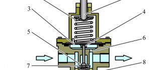
Adjustable throttle device
The flow area made in the throttle body 1 varies depending on the position of the shut-off and control element. The example presented shows a needle throttle with a conical shut-off and control element.
At the moment the surfaces of the cone and the hole in the body touch, the flow area of the throttle will completely close; in this case, fluid flow through the throttle is impossible.
As you rotate the handle, the cone will move. When it moves to the left, the flow area of the throttle will increase, and when it moves to the right, it will decrease.
Working fluid flow control
To change the speed of movement of the rods of double-acting hydraulic cylinders or the speed of rotation of the drive shafts of reversible hydraulic motors, hydraulic devices are used to control the flow of working fluid (WF), which, depending on the properties, are divided into two main designs: throttling and regulating.
Throttling hydraulic devices are designed to create hydraulic resistance to flow by throttling the fluid flow, which in turn depends on pressure loss. Throttling hydraulic devices include flow synchronizers (flow dividers and adders) and unregulated and adjustable hydraulic throttles, including with or without a check valve.
Controlling hydraulic devices are designed to maintain a given flow rate regardless of the pressure difference in the incoming and outgoing flows of the Russian fluid. Regulating hydraulic devices include two-line flow regulators with variable output flow rate and stabilization depending on the temperature of the fluid, and three-line flow regulators with variable output flow rate with drainage of excess flow into another hydraulic line or into the hydraulic system tank.
Most throttling hydraulic devices are local hydraulic resistances, in which the change in flow rate depends on the flow area due to the loss of pressure P due to deformation of the fluid flow.
Types of flow sections of chokes
Let's look at the most common types of adjustable chokes.
Needle choke
A conical or needle-shaped shut-off-adjustable element closes the hole. The throttling gap in the rearranged design is short, the wetted perimeter is small.
The main advantage of a needle throttle is the insignificant effect of viscosity on the characteristics, and the disadvantage is sensitivity to the purity of the working fluid due to the possibility of blockages getting into a small gap at low flow rates.
Slot choke
The shut-off and control element, moving in the sleeve, completely or partially blocks the throttling hole.
Like a needle throttle, it is sensitive to contamination, but is suitable for operation in a wide range of working fluid viscosity.
A slot throttle is best used to regulate high flow rates.
Throttle with longitudinal groove
The shut-off and control element has an inclined flat and a groove of rectangular or triangular cross-section. The value of the throttle resistance is determined by the position of the shut-off and control element relative to the hole made in the sleeve.
The throttling gap in devices of this type is relatively short, and the wetted perimeter is small.
Throttles with a longitudinal groove are well suited for operation at low flow rates.
Calculation of flow through a throttle
The amount of fluid flow through the throttle depends on the size of the throttle gap and the pressure drop across the throttle. The flow rate through the throttle can be determined by the formula:
where Q is the flow rate, A is the flow section area of the throttle gap, ΔP is the pressure drop across the throttle, ρ is the density of the working fluid, k is the flow coefficient (k = 0.6. 0.9)
Since the flow rate through the throttle gap depends on the pressure at its inlet and outlet, chokes are used to regulate the speed of movement of the output links of hydraulic motors (for example, hydraulic cylinders) with a constant load, or in drives where a change in speed when the load changes is acceptable or desirable.
If the load influences the speed of movement of the load output link, special devices are used - flow regulators.
Throttle regulation
A throttle is a hydraulic resistance that is installed to regulate the flow of fluid, and therefore the speed of the output link of the hydraulic drive. Throttle designs will be discussed below.
The speed of movement of the piston in the cylinder or the speed of rotation of the hydraulic motor shaft can be adjusted by changing the throttle resistance.
Depending on the location of the throttle installation in the hydraulic drive circuit in relation to the hydraulic motor, three methods of throttle control are distinguished:
— choke “at the input” (Fig. 13.16);
— choke “at the output” (Fig. 13.17);
- choke “on the branch” (Fig. 13.18).
Fig.13.16 Fig.13.17 Fig. 13.18
throttling devices. By design, chokes are divided into unregulated (designation) and adjustable (designation), and according to the type of hydraulic losses in the chokes - linear and nonlinear.
In linear chokes, the movement of fluid is prevented by frictional resistance of the fluid against the channel walls. To obtain higher resistances, the channel cross-section is reduced and the length is increased. In throttles of this type, a laminar regime of fluid movement is established, in which the pressure drop is directly proportional to the first power of speed or flow and can be calculated using the formula
,
where d is the diameter, for example, of a capillary; — coefficient of dynamic viscosity; l
- length; — pressure drop across the throttle.
An example of a linear unregulated choke is a capillary. built into the main pipeline (Fig. 13.19). To increase the flow rate, install a package of capillaries (Fig. 13.20).
Fig.13.19
Fig.13.20
An example of a linear adjustable throttle is a plug with a screw thread placed in a body well-fitted along the outer diameter (Fig. 13.21). The cutting length can be changed, therefore, the flow through the throttle will also change.
Fig.13.21
It should be noted that the operation of a system with a linear throttle is unstable, since its resistance depends on the viscosity of the liquid, which changes with temperature.
In nonlinear chokes, local resistances in the form of diaphragms and nozzles are widely used. In throttles of this type, a turbulent regime of fluid movement is established, in which the pressure drop is proportional to the second power of speed or flow; the latter can be calculated using the formula
,
where is the flow coefficient; — throttle opening area; — pressure drop across the throttle.
An example of a nonlinear unregulated throttle is a calibrated hole (diaphragm) 1 installed in the main fluid flow (Fig. 13.22), or a package of plastic chokes.
Fig.13.22
Examples of nonlinear unregulated chokes can be spools and valves of various designs (Fig. 13.23).
Fig.13.23
Since in a nonlinear throttle energy losses are associated with flow separation and vortex formation, and losses from friction are minimal, the hydraulic resistance of such a throttle is practically independent of fluid viscosity and temperature changes. Nonlinear chokes ensure stability of the characteristic Q=f(Δp) over a wide range of Re numbers.
analysis of the operation of a hydraulic drive with throttle control. In throttle control systems, a characteristic condition is inequality
,
and in relation to the hydraulic drive of translational motion
(13.2)
where Qн – pump flow; — effective area of the hydraulic cylinder; Vmax is the maximum speed of the hydraulic cylinder rod.
Under this condition, the excess part of the liquid from the pump is discharged through the overflow valve into the hydraulic tank without performing any work.
System with a choke “at the input” (Fig. 13.24).
Fig.13.24
In the hydraulic system, between pump 1 and hydraulic distributor 3, a throttle A is installed, the setting of which determines the speed of the piston in cylinder 4. If condition (13.2) is maintained, then excess liquid is discharged through overflow valve 2, while a constant pressure is maintained in the discharge cavity of the pump and in front of the throttle , corresponding to the setting of valve 2.
Let's consider the operation of this system and find out how a change in the payload P affects the piston speed while keeping the throttle setting unchanged.
Let's assume that the piston and rod move to the right. Let us denote the pressure of the working fluid in the left cavity as rrab, in the right cavity as rpr (backpressure), the friction force as T, and the payload as P.
Let's create the equilibrium equation for the piston of the power cylinder:
.
In this equation, the friction force T and the force from the back pressure can be taken as constant.
Therefore, if the external load P changes, then the pressure pwork must change. Since throttle A is installed in series with the hydraulic cylinder, then Qdr = QHz. Flow, for example, through a non-linear throttle
;
.
Since rp.k. = const, the flow rate through the throttle, and therefore the speed of the hydraulic cylinder piston, will change with changes in the external load P.
A system with a throttle at the input allows regulation of the speed of the hydraulic motor only if the direction of the load does not coincide with the direction of movement of the output link. Indeed, if the load is directed in the same direction as the movement of the output link of the system, then when the fluid supply through the throttle is reduced, the piston can move faster than the cylinder cavity is filled. There will be a rupture in the flow in the line in front of the piston.
In addition, for example, in lifting machines, the lifted load may fall when lowered, since the external load - the load - will overcome only the friction force of the piston on the cylinder and the back pressure in the drain line when lowering. Therefore, to stabilize the friction forces, a retaining valve 5 (or damper) is installed on the drain line, creating a back pressure ppr in the non-working cavity of the cylinder. The back-up pressure should not be more than 0.2...0.3 MPa.
System with output choke . In the hydraulic system (Fig. 13.25), throttle B is connected to the drain line after distributor 3. The piston speed here is determined by the volume of liquid that is displaced from the rod cavity of cylinder 4 through throttle B into the hydraulic reservoir.
Fig.13.25
Let us analyze the operation of this system and establish the effect of changes in load P on the piston speed.
Let's create the equilibrium equation for the piston of the power cylinder:
.
If the condition under which > is maintained, then the pressure prab does not change in the process and corresponds to the setting of the overflow valve 2 rp.k, i.e. . The friction forces T for this mechanism are almost unchanged. Since, according to the load condition, P is a variable value, it follows from the equilibrium equation that the back pressure rpr will also be variable.
The pressure before the throttle “B”, with some assumption, can be taken equal to ppr, and after the throttle – almost atmospheric rat. Therefore, the pressure drop in the throttle when the latter is connected at the output is a variable value. Consequently, the fluid flow through the throttle and the piston speed will be variable.
A system with an "output" choke is preferable to a system with an "input" choke. Firstly, the heat generated when passing through the throttle is transferred to the hydraulic reservoir without heating the hydraulic motor. Secondly, it is advisable to use this system in mounting mechanisms, because By closing throttle B, you can instantly stop the lifted load in the desired position.
In the throttle control systems discussed above, the power consumed by the pump is constant and independent of the external (useful) load P.
System with choke on branch. Let's consider the third possible way to connect a choke to the system - on a branch (Fig. 13.26).
The fluid flow coming from pump 1 is divided in two directions: to the hydraulic cylinder 4 through the distributor 3 and through the throttle C, which is installed in a branch parallel to the power cylinder. The piston speed, as in previous systems, is determined by the throttle setting C.
Fig.13.26
When the throttle is closed, the piston speed is maximum. As it opens, part of the liquid begins to circulate into the hydraulic reservoir, and the piston speed decreases accordingly. If, when the throttle is fully opened, the resistance exerted by it and the line after the throttle is less than in the cylinder-piston group and retaining valve 5, then all the liquid from the pump will be discharged through the throttle into the hydraulic reservoir, and the piston will stop.
With the indicated location of the spool in the distributor 3, the piston cavity of the hydraulic cylinder 4 is connected to the pump, the pressure in which pwork is determined by the load P + T. If the load changes during operation, the pressure drop in the throttle depends on the load. Consequently, the fluid flow through the throttle and the speed of the output link change.
Valve 2 in the system comes into operation sporadically at the time of overload, thus performing only the function of a safety device.
The power consumed by the pump and the pressure in the discharge cavity are proportional to the payload, therefore a hydraulic system with a throttle installed parallel to the power cylinder is more economical than systems with an “inlet” and “outlet” throttle, since the efficiency her higher.
From an analysis of the operation of hydraulic systems with a throttle method of speed control, it follows that, regardless of the location of the throttle, constancy of the piston speed is not ensured with a constant throttle setting if the load changes during operation. This is explained by an unstable pressure drop in the throttle.
Therefore, a device naturally arises in which the pressure drop across the throttle would be automatically maintained constant as the load on the output link changes. This device is called a throttle regulator. This device consists of a throttle and a pressure reducing valve located in a common housing. The fluid flow is set by a throttle, and the constancy of the pressure difference before and after the throttle is ensured automatically by a pressure reducing valve.
Versions of industrial chokes
In industrial hydraulic drives, chokes of butt, flange, modular, and built-in installation are used.
Butt and flange mounted chokes are usually manufactured for high flow rates.
Built-in chokes are placed in a special mounting plate in which the corresponding channels are made, or in a housing that can provide threaded, flanged, modular or butt mounting.
Modular installation allows you to place the throttle together with other elements in a common modular plate.
Types of hydraulic throttles
The figure shows the designations of two types of hydraulic throttles:
a) adjustable type; b) unregulated type.
In the diagram, the throttle is indicated as a narrowing of the flow. The arrow indicates that it is possible to change the resistance from the outside. Type (a) (adjustable throttles) includes products in which the cross-sectional area of the working flow changes due to external influence.
Hydraulic throttles are classified according to the design of the shut-off element. The most common:
Operating principle
A change in hydraulic resistance creates a pressure difference between the nodes of the hydraulic circuit.
The pressure drop is directly dependent on the flow rate and flow area and inversely dependent on the density of the working fluid.
The relationship is described by the expression:
Q = µ∙S
µ – flow coefficient (≈0.7);
ρ – liquid density, g/cm3.
The speed of operation of the mechanism is also affected by the geometry of the throttling slot, which can be conical, straight, circular, etc.
An important parameter is the throttle characteristic. This is the dependence of the pressure drop in the distributor on the flow rate of the working liquid medium passing through it. According to the type of the corresponding equation, hydraulic throttles can be linear and quadratic (nonlinear).
Hydraulic throttles, adjustable, with check valve
A hydraulic throttle is a local hydraulic resistance designed to reduce pressure in the flow of working fluid. It is very important in the operation of modern hydraulics.
The hydraulic throttle is a regulating hydraulic device. Its peculiarity is that the fluid flow passing through the hydraulic throttle does not affect the size of its flow area.
The characteristic of a hydraulic throttle is understood as the dependence of the pressure loss in the hydraulic throttle (pressure drop across the hydraulic throttle) on the flow rate Q of the working fluid passing through it. Based on the type of this dependence, linear and quadratic chokes are distinguished.
Linear hydraulic throttles
Other names are viscous or inertial. The flow section has a straight profile. Pressure loss and flow rate across the throttle vary depending on the length of the channel. A laminar fluid flow is created inside. Therefore, this type can only be used in low-power systems with pressure losses below 0.3 MPa.
The longer the passage channel, the higher the cross-sectional area, which protects the hydraulic throttle from the accumulation of dirt and debris on the surface.
A significant disadvantage of the linear design is the dependence on the viscosity of the liquid and, as a consequence, on the flow temperature. This sharply limits the use of devices in the case of large engine volumes.
Buy hydraulic throttle, adjustable and unregulated, in Chelyabinsk
DKM DR and DK DRZh KVMK MDO PG77
| Name | Description |
| Hydro throttle DKM 6/3 | Order |
| Hydro throttle DKM 10/3 | Order |
| Hydro throttle DK22/3M… Gomel | Order |
| Name | Description |
| Hydro throttle DKS 32 | Order |
| Hydro throttle DRS 32 | Order |
| Name | Description | |
| Throttle Lubricant DRZh 20 | Order | |
| Throttle Lubricant DRZh 25 | Order |
| Name | Description |
| Hydro throttle KVMK 10G 1.1 | Order |
| Hydro throttle KVMK 16G 1.1 | Order |
| Hydro throttle KVMK 25G 1.1 | Order |
| Hydro throttle KVMK 32G 1.1 | Order |
| Name | Description | |
| Track hydraulic throttles MDO-203S (butt) | Order | |
| Track hydraulic throttles MDO-203 (pipe) | Order |
| Name | Description | ||
| Hydro throttle PG77-12 | price | Order | |
| Hydro throttle PG77-14 | price | Order |
| Name | Description | ||
| Flow indicator UP-10 | price | Order | |
| Flow indicator UP-16 | price | Order |
Nonlinear hydraulic throttles
This is a common type of chokes because... its operation is practically not affected by the temperature of the liquid, and the flow regime inside is turbulent. This allows the devices to be used in powerful hydraulic drives.
The characteristic is described by the quadratic dependence of the pressure difference on the flow rate. At high fluid speeds, local resistance causes turbulence and deformation of the flow. Movement control occurs by changing the number of resistances or the cross-sectional area of a quadratic inductor.
Classification by types of regulation and device
According to the type of control, hydraulic throttles can be controlled or uncontrolled. In the first case, the operator can vary the size of the passage channel; in the second, the working section area is not subject to change. In practice, the uncontrolled type is often combined with other regulatory mechanisms.
Based on the type of design, hydraulic throttles are divided into direct-acting devices and speed regulators. The fluid flow rate in a direct-acting throttle depends on the pressure difference at the inlet and outlet. In the speed controller, the flow rate of the working fluid does not depend on external loads and is a constant value.
Adjustable hydraulic throttles
Let's look at the most common types.
Slotted. Widely used, including on large-volume hydraulic motors. A hollow plug with a slot for flow is installed in the passage hole. When the plug is rotated, the cross-sectional area changes. Thus, flow viscosity has no effect on throughput. The disadvantage is susceptibility to contamination.
Needle. The shut-off and control element has a cone shape. The throttling hole is short, the washed surface is small. As in the previous version, the characteristic does not greatly depend on the viscosity and temperature of the liquid. However, there is a high risk of clogging.
Three-way throttling valves with fixed jet – FR*A
Sun Hydraulics tri-line fixed jet throttling valves with pressure compensation combine bypass and restriction functions. The distributors contain in their design a replaceable fixed jet for adjusting the main flow exiting through line 3. Main operational characteristics:
- Possibility of manufacturing jets of various capacities - from 0.4 to 200 l/min, depending on the standard size (there are five standard sizes in this series);
- Both the main and bypass flows can be used to adjust the operating pressure of the hydraulic system;
- As the inlet flow increases, the accuracy of the main flow adjustment decreases if the pressure in the main line becomes greater than in the bypass. If the pressure in the bypass line exceeds the pressure in the main line, the accuracy of flow control is maximum. See performance charts in the appropriate sections of the catalogue;
- Stable operation under wide temperature fluctuations;
- Flow through the bypass line is not possible if the main flow parameters are not adjusted;
- When flow in the main line is blocked, the bypass line is also blocked.
- In this regard, it is recommended to install a safety valve after the valve in the main line;
- The nominal flow rates established during production are within +/- 15% of the values specified by the customer;
- As an option, it is possible to manufacture throttles with an adjusting screw, which allows you to adjust the flow within +/- 25% of the factory setting.
Forms of hydraulic throttles
The simplest design resembles a washer or a combination of washers in appearance. These chokes typically have sharp edges to prevent contamination.
More complex and voluminous products (non-linear) have a square shape. For high-speed and powerful flows, it is recommended to use a set of throttles simultaneously (packet hydraulic throttles). This solution minimizes the risk of failure. The number of washers determines the resistance force. When calculating such chokes, the relative position of the washers and the distance of the holes from each other are taken into account. The diameters of the passage holes also matter.
Among quadratic throttles, from the point of view of calculations, the simplest is a hydraulic throttle with a spool shut-off and control element.
The phenomenon of obliteration
In a technical sense, obliteration is the covering of a hole’s cross-section during operation. For a throttle, the working cross-sectional area cannot be reduced indefinitely. There is a lower limit, upon reaching which the stability of the throttle decreases sharply.
Solid inclusions contained in working media can be retained by the material of the locking elements and settle in microcracks. There is a gradual accumulation of particles. If their dimensions approach the dimensions of the gap, there is a risk of complete overgrowth with loss of throughput function. The flow rate will be restored when the working window expands.
In addition to mechanical contamination, obliteration can also be caused by the adsorption of polarized liquid particles by the walls of the throttling slit. Over time, the molecules form a layer up to 10 microns thick, affecting local resistance.
The flow area gradually decreases. With small working sections, complete obliteration may occur. You can get rid of the layering of particles by rotating or translational movements of one of the surfaces relative to the other. The destruction of the adsorbed layer of polarized particles will lead to the restoration of the required flow rate.
To prevent the adsorption of molecules, changes are made to the design, providing for oscillations or rotation of the throttle working fluid. As a result, the passage window does not become clogged and does not trap polarized molecules. Obliteration does not occur.