The main purpose of a car transmission is to transfer force from the engine to the drive wheels with minimal losses. Some machines have mechanisms that require a source of energy to perform their assigned functions. It is irrational to install an additional internal combustion engine or electric motor, so the main engine of the car is used as a drive. To direct the power flow from the main kinematic circuit, a power take-off is used. From one to three similar mechanisms can be installed on vehicles.
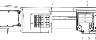
Examples of PTO installation locations
Types of power take-offs
The additional power take-off box serves to transfer energy to equipment installed on the vehicle. Depending on the type of driven mechanisms and the requirements for the device, the characteristics of the KDOM may differ:
- by the number of steps that determine the step between operating modes;
- the possibility of providing the reverse required for the mechanism, for example, the pump requires rotation only in one direction, and the power take-off of a truck crane must be capable of operating in both directions;
- the value of gear ratios that provide a change in angular velocity and transmitted torque;
- the number of shafts structurally included in the PTO;
- the location of the components included in the power take-off device;
- a control signal, which can be purely mechanical, made using a lever, or issued by the car’s on-board computer.
According to the installation location, there are PTOs that are mounted:
- on the side of the gearbox;
- from the end of the gearbox;
- in the gearshift device housing;
- in conjunction with the distribution.
Appearance of the COM
The method of lubricating the power take-off gears depends on the method of its installation and the presence of its own oil container. Typically, oil from the crankcase of the main unit is used. When the mechanism is located at the top, a pump is used to supply lubricant to the PTO.
KamAZ-5511: simple and reliable dump truck
The popularity of this dump truck is evidenced by the fact that its production lasted more than 13 years: from 1977 to 1990. Distinctive features of KamAZ-5511 are its high reliability. Easy to operate, high cross-country ability and multifunctionality. Not only dump bodies were installed on the KamAZ-5511 chassis, it was also used and is used as a concrete mixer truck (mixer), a grain truck, and other manipulators and superstructures were installed on it. The truck stood out against the background of its fellow trucks with its bright orange color – such a color was very unusual in the 70-80s.
The car is a reliable, easy to maintain and repair, three-axle frame structure with two drive axles (six by four wheel arrangement). A standard KamAZ tilting cabover cab is installed in the front part of the chassis, under which the power unit is located. Most of the components and parts of the KamAZ-5511 are unified with other trucks of the Kama Automobile Plant, but the dump truck received an upgraded hazard warning system and headlights with asymmetric lighting (the chance of blinding the driver of oncoming traffic was reduced).
A traditional all-metal cabin was installed on the KamAZ-5511 chassis; the interior was not distinguished by comfort and the presence of a large number of instruments. The cabin is equipped with two air-suspended seats (a sleeping bag is not provided), an autonomous heater and a fan. The instrument panel is single-section, made of metal, the placement of instruments and indicators often causes complaints from drivers. At the same time, it should be noted the presence of power steering, good warmth and sound insulation of the cabin, which, moreover, received a high roof.
Despite the fact that production of KamAZ-5511 ended back in 1990, this model is widely represented on the secondary market. It can be difficult to answer the question of how much such a car costs. It all depends on the technical condition, year of manufacture and mileage of a particular car.
A truck manufactured in the late 70s - early 80s will cost 150 - 250 thousand rubles. Cars of the last years of production (1988-1990) are sold at a price of 350-400 thousand rubles.
Reversible box
The PTO shown in the figure below is designed for installation in the side of the gearbox housing. The useful power is taken from the intermediate shaft of the gearbox. The gears are in continuous mesh.
Reversible box
The control lever has 3 fixed positions for selecting the operating mode of the power take-off. In the right position, direct transmission is carried out. In this case, the carriage with a gear wheel is constantly in engagement with the intermediate shaft of the gearbox. When moved to the extreme left position, reverse is activated. To ensure reverse motion, the gear wheel is connected to a gear installed inside the PTO gearbox. When moving to the middle position, the driven shaft stops rotating and the additional power take-off box goes into the off position.
Power take-off without gearbox
The main difference between gearless PTOs is their simplicity of design and single gear ratio. The image below shows the Ural power take-off, designed to drive a winch. It is mounted to the end of the transfer case, allowing it to receive torque from the input shaft through a movable coupling. Power take-off occurs from the input shaft.
PTO without gearbox
The mechanism is controlled using a special fork. The power take-off is activated by blocking the transfer case input shaft and PTO using a carriage. The lever has two fixed positions. The left one corresponds to power transmission, and the right one corresponds to the off state. The PTO does not provide reverse. To engage the reverse direction, you need to select reverse gear using the gearbox selector.
The parts are lubricated by a plunger pump. This allows the attachment to be used on a stationary vehicle. The pump is located in a special boss of the PTO cover. It also helps lubricate the transfer case.
PLATFORM LIFTING MECHANISM
Technical description
The lifting mechanism (Fig. 240) is hydraulic and consists of a power take-off box, an oil pump, a hydraulic cylinder, a control valve, a platform lift limiting valve, electro-pneumatic valves, an oil tank with a filter and a system of pneumatic and hydraulic lines. In addition to the specified standardized components, the platform lifting mechanism of the KamAZ-55102 dump truck has a locking device designed to connect the hydraulic system of the tractor with the hydraulic system of the trailer, and a distributor that serves to distribute the oil flow either to the hydraulic cylinder of the tractor or to the hydraulic cylinder of the trailer. The distributor is attached to the control valve.
Rice. 240. Schematic diagram of the platform lifting mechanism: a - KamAZ-5511 dump truck: 1, 4, 19 - electro-pneumatic valves; 2—control valve; 3, 17, 20—pneumatic chambers; 5—24 V current source; 6—fuse; 7—power take-off switch; 8—switch for raising and lowering the platform (1—lowering; 11—raising); 9—indicator lamp for turning on the power take-off; 10—hydraulic cylinder; 11—limit valve; 12—filter safety valve; 13—filter; 14—oil tank; 15—pump; 16—power take-off; 18—hydraulic system safety valve; b — road train KamAZ-55102: 1—hydraulic cylinder of the trailer; 2—hydraulic cylinder of the tractor; 3—limit valve; 4— filter safety valve; 5—filter; 6—hydraulic system safety valve; 7—oil tank; 8—pump; 9—power take-off; 10, 12, 14 and 16—pneumatic chambers; 11, 17, 18, 19—electro-pneumatic valves; 13—control valve; 15—distribution edge; 20— switch for the platform lifting mechanism (I—lowering; II—raising); 21—control lamp; 22— hydraulic system distributor switch for tractor or trailer; 23—indicator lamp for turning on the power take-off; 24—power take-off switch; 25—fuse; 26—24 V current source; 27—locking device
Below is the technical specification of the platform lifting mechanism:
| Automobile | KamAZ-5511 | KamAZ-55102 |
| Lifting mechanism control | electro-pneumatic, remote, from the driver's cabin, two switches mounted on the instrument panel | |
| Power take-off | from the gearbox via the power take-off | |
| Transmitted power (average), l. With. | 12 | 10 |
| Efficiency | 0,7 | 0,7 |
| Maximum working pressure, kgf/cm 2 | 140 | 140 |
| Working stroke time (raising a loaded platform) at an engine crankshaft speed of 2300 rpm, s, no more | 19 | 18 |
| Idling time (lowering empty platform), s, no more | 18 | 16 |
| Fuel consumption per 100 operating cycles, l | 5,5 | 5,5 |
| Power take-off ratio | 0,59 | 0,59 |
| Total gear ratio from the engine crankshaft to the driven shaft of the hydraulic pump | 1,26 | 1,26 |
| Recommended engine speed, rpm | 2200—2500 | |
| Number of stages (retractable hydraulic cylinder units) | 3 | 5 |
| Diameter of retractable links, mm | ||
| first | 95 | 142 |
| second | 75 | 117 |
| third | 56 | 95 |
| fourth | — | 75 |
| fifth | — | 56 |
| Working stroke of retractable links, mm | ||
| first | 1100 | 362 |
| second | 1140 | 354 |
| third | 1160 | 190 |
| fourth | — | 354 |
| fifth | — | 349 |
| general | 3400 | 1773 |
| Maximum force when extending links, kgf | ||
| first | 9900 | 26300 |
| second | 6200 | 15000 |
| third | 3450 | 9900 |
| fourth | — | 6200 |
| fifth | — | 3450 |
Power take-off (Fig. 241)—with an oil pump, attached to the gearbox housing on the right side. Between the flanges of the power take-off housing and the gearbox, sealing gaskets are installed, with the help of which the mesh of the gears is adjusted at the factory. Therefore, if it is necessary to replace the gaskets, their overall thickness must be maintained.
The drive gear 7 of the power take-off is fixed at one end of the drive gear axis, the other end of which enters the cavity of the diaphragm chamber and is connected to the diaphragm 3. The cavity of the diaphragm chamber is closed by a cover 1 with a threaded hole for air supply. The diaphragm is held by spring 4 in its uppermost position. The axis of the drive gear is kept from rotating by a set screw 5, the end of which fits into the groove of the axis. When air enters the chamber cavity, the axis with the drive gear moves above the diaphragm. The drive gear has two ring gears, one of which is permanently connected to the intermediate gear of the power take-off, and the other engages with a gear half-coupling 9, which transmits rotation through the prism 10 and clutch 11 to the drive shaft of the pump 13. When air is released from the working cavity of the diaphragm chamber the spring disengages the drive gear from the gear half-coupling, while the connection with the intermediate gear is not interrupted.
The power take-off can only be turned on when the air pressure in the vehicle's pneumatic system is at least 5 kgf/cm 2 and when the clutch is disengaged.
Since January 1984, a modernized power take-off (PTO) of increased reliability has been introduced on KamAZ-5511 and -55102 dump trucks.
Rice. 241. Power take-off: a - before improvement: 1 - cover; 2—washer; 3—diaphragm; 4—spring; 5—set screw; 6, 8, 17—bearings; 7—drive gear; 9— gear half-coupling; 10—prism; 11—coupling; 12—gasket; 13— pump; 14, 15, 16—circlips; 18—idler gear; 19—bolt; 20, 21—o-rings; b — after improvement; 1—cork; 2 and 21—gaskets; 3—idle gear axis; 4 and 16—washers; 5 and 23—bearings; 6—idler gear; 7—thrust ring; 8—lock washer; 9—nut; 10 and 12—rings; 11—compensator; 13—adjustment screw; 14—PTO housing; 15—spring; 17—pneumatic cylinder body; 18—O-ring; 19—piston; 20—pump NSh32-L-2; 22—half coupling; 24— gear
In the crankcase 14 (Fig. 241, a) the driven gear 24 is placed in ball bearings 23. On the axis 3 on ball bearings 5, using a nut 9 and a washer 8 with a bending antenna, the intermediate gear 6 is fixed. The axis is protected from rotation by a set screw 13. During assembly, the screw it is screwed into the crankcase 1 until it stops at the bottom of the groove on axis 3, and then it is unscrewed 1.5 turns and opened. This ensures that the axis can move in the longitudinal direction.
The end of the axle with a piston 19 attached to it with a cuff 18 enters the body of the pneumatic cylinder 17, which is attached to the PTO housing. In the initial position, the axis is held by spring 15. Oil leakage from the PTO cavity into the pneumatic cylinder cavity is prevented by ring 12. To connect to the pump shaft, a half-coupling 22 is used, which is connected through a compensator 11 to the driven gear 24, which compensates for possible distortions of the axis of rotation of the driven gear and the pump shaft when installing the pump on COM.
In the initial position, the intermediate gear is in constant engagement with the gearbox gear. When compressed air is supplied to the pneumatic cylinder body, the intermediate gear moves to the left and its ring gear engages with the driven gear ring. The torque from the driven gear is transmitted to the pump shaft.
It should be noted that when installing a modernized PTO, a left-hand rotation NSh32-2 pump is used, which entails the use of modified high and low pressure pipelines from the pump to the control valve and oil tank. This remark must be taken into account when replacing old PTOs in operating organizations with modernized ones.
The oil pump is gear type, high pressure. The pump flow is 56 l/min at a shaft speed of 1900–2000 rpm.
To ensure normal operation of the pump and increase its service life, it is necessary to carefully filter the oil poured into the tank.
The hydraulic cylinder of the KamAZ-5511 vehicle lifting mechanism is telescopic, plunger, single-acting (Fig. 242). The housing 15 of the hydraulic cylinder contains retractable links 14, the stroke of which is limited when extending by locking rings 13, and when moving downwards by locking rings 18. The direction of the retractable links is ensured by guide half rings 17 and bushings 9, which are held by locking rings 7. To increase the performance of the hydraulic cylinder, the outer surfaces of the retractable The links are knurled, chrome plated and polished. The retractable links are sealed with rubber cuffs 11, located between spacers 12 and protective rings 10. The cavity of the hydraulic cylinder is protected from dust and dirt from the outside by cleaners 8. A bottom 5 is inserted into the body of the hydraulic cylinder from below, the shoulder of which is connected to the shoulder of the body by half rings 20. The half rings are connected by a clamp 19, fastened with a bolt 3, locked with a washer with bent antennae. The hydraulic cylinder has ball heads 6, the spherical part of the ball head is fixed in the hydraulic cylinder support 22, forming a movable connection. Ceramic-metal liners ensure the operation of this connection without lubrication.
A pipe 16 with a threaded end is welded to the body of the hydraulic cylinder, to which a high-pressure hose is attached.
Rice. 242. Hydraulic cylinder: 1—hydraulic cylinder support; 2—liner; 3—nut; 4— ball head; 5—lock washer; 6 and 10—thrust rings; 7—wiper clips; 8—cleaners; 9—washers; 11—protective rings; 12—cuffs; 13—spacers; 14—plungers; 15 and 19—split rings; 16—hydraulic cylinder body; 17—pipe; 18—half rings; 20— half ring of the clip; 21—clamp; 22—bottom of the hydraulic cylinder; 23—bolt
The control valve (Fig. 243) is used to control the flow of working fluid in the hydraulic system of the tipping mechanism. Seats 4, 17 of valves 18, 5 are pressed into body 1 of the control valve and nuts 16, 10 are screwed in, serving as guides for pushers 15, 7. A special connection of valves with dovetail pushers prevents the valves from jamming in the seats if the axes of the pushers and seats do not coincide . Pushers with attached valves at one end and the other ends, on which diaphragms 13 and 6 are attached, enter the cavities of pneumatic chambers closed by covers 14, 8. Spring 12 of pusher 15 holds valve 18 in the open position, and spring 9 presses valve 5 to the seat. The pushers are sealed with rubber rings 11, and the pusher 7, in addition, has a drainage hole B.
In the neutral position, oil from the pump through the pipeline through the opening of fitting 19 enters the control edge and, passing through the open valve 18, goes to drain through fitting 21.
When air is supplied to the cavity of the pneumatic chamber above the diaphragm 13, valve 18 closes. At the same time, air is supplied to the cavity of the pneumatic chamber under the diaphragm 6 and valve 5 opens. Oil passes through valve 5 and fitting 2 into the cavity of the hydraulic cylinder. When air is released from the cavities of the pneumatic chambers, valve 5 closes and valve 18 opens. Since valve 5 is closed, the hydraulic cylinder line is blocked and the platform is held in a raised position, and the oil, when the pump is running, goes from it to drain through valve 18 of the control valve.
If air enters only into the cavity of the pneumatic chamber under the diaphragm 6, valve 5 opens and oil from the cavity of the hydraulic cylinder goes through this valve and valves 18 to drain. A safety valve 20 is screwed into the control valve body, which, when screwed in with collar B, cuts into the body of the control valve body and disconnects the pressure and drain lines. In case of overload, the pressure in the system increases and the safety valve is activated, releasing oil into the oil tank.
The platform will stop lifting until the overload is removed. The response pressure of the safety valve is strictly adjusted at the factory, and changing it during operation is prohibited.
Rice. 243. Control valve: 1—control housing; 2, 19, 21—fittings; 3—sealing rings for fixed joints; 4, 17—valve seats; 5, 18—valves; 6, 13—diaphragm; 7, 15—pushers; 8, 14—pneumatic chamber covers; 9, 12—springs; 10, 16—guide nuts; 11—sealing rings for movable joints; 20—safety valve; B—drainage hole; B—shoulder
The platform lift limitation valve ( Fig. 244) is fixed to the bracket of the first cross member of the subframe. A bushing 1 with an o-ring 5 is screwed into the housing 6. A rod 4 with an adjusting bolt 2 at one end passes into the hole of the bushing, the other end of which faces the valve 8. The adjusting bolt ends with a spherical head and is locked with a lock nut 3. In the closed position, the valve is pressed against the body spring force 7.
When you press the spherical head of the adjusting bolt, the rod moves and opens the valve, while the pressure and drain lines communicate.
Rice. 244. Platform lift limitation valve: 1—bushing; 2—adjusting bolt; 3—lock nut; 4—rod; 5—o-ring; 6— body; 7—spring; 8—valve
The electro-pneumatic valve (Fig. 245) consists of housing 3, housing cover 1, electromagnet 4, rod 5, springs 6, valves 8. Air from the cylinder is supplied to terminal I into the cavity in the valve cover. When the electromagnet is turned on, the rod, extending, presses the upper valve 8 to the housing seat. In this case, the lower valve 8 moves away from the seat and air from the cavity in the valve cover through the valve in the body and terminal III flows to the pneumatic actuating chambers installed on the power take-off box or control valve. When the electromagnet is turned off, the lower valve is pressed with the help of a spring to the housing seat, and the upper valve moves away from the seat. The air from the pneumatic chamber escapes into the atmosphere through outlet II.
Rice. 245. Electro-pneumatic valve: 1—cover; 2—fitting; 3—body; 4—electromagnet; 5—rod; 6—spring; 7, 9—gaskets; 8—valve
The oil tank is stamped from two halves. At the top of the tank there is a filler neck and a filter mounting flange, at the bottom there is an oil drain hole, closed with a threaded plug, and a suction pipe. A filter mesh is installed in the filler neck. The neck is closed with a threaded cap with a hole connecting the tank cavity to the atmosphere, and an oil level indicator with lower and upper marks. The oil level in the tank should be within these marks. The level is measured with the platform lowered. To prevent dust and dirt from entering through the hole in the filler cap, a hair pack is provided. The oil tank filter is attached to the flange on the drain line.
Oil tank filter (Fig. 246). From the drain line, oil flows through pipe 4 into the cavity of filter housing 2 and through filter elements 3, filter pipe 1 goes into the tank. If the filter elements are excessively clogged, the pressure in the drain line increases, as a result of which ball valve 5 opens and the oil is drained into the tank, bypassing the filter element.
Rice. 246. Oil tank filter
The hydraulic cylinder of the KamAZ-55102 dump truck (Fig. 247), in contrast to the hydraulic cylinder of the KamAZ-551 I dump truck, has five retractable links. It is attached to the subframe by pin 1, which has a threaded hole for connecting a high-pressure hose. A bottom 20 with a hole for a plug 21 to drain the sludge is screwed onto the hydraulic cylinder body from below. Ball head 6 is attached to the hydraulic cylinder plunger using a locking ring 10.
Rice. 247. Hydraulic cylinder for lifting the platform of a KamAZ-55102 dump truck: 1—trunnion; 2—spacer; 3—protective ring; 4—mud lifter; 5—hydraulic cylinder support; 6— ball head; 7—insert; 8—liner; 9— locking screw; 10—ring for fastening the ball head; 11—retaining ring of the guide sleeve; 12—guide bushing, 13—cuff; 14—upper retaining ring; 15—hydraulic cylinder body; 16—retractable link; 17—O-ring; 18—guide half-ring; 19—bottom retaining ring; 20—bottom of the hydraulic cylinder; 21—drain plug
A distributor is attached to the control valve (Fig. 248), which serves to distribute the oil flow either to the hydraulic cylinder of the tractor or to the hydraulic cylinder of the trailer. In body 1, with the help of retaining rings 5, seats 6 are installed, through which valves 7 and 8 pass. The threaded end of valve 8 with diaphragm 12 enters the cavity of the pneumatic chamber, closed by lid 13. Spring 11 holds the valve in the extreme left position. The seats of the bushings and valve are sealed with rings 9 and 10, respectively. Possible leaks through the valve seals are removed on the one hand through the drain hole of the plug 4, on the other through the hole in the pneumatic chamber under the diaphragm.
The oil passes through the hole in the distributor body under valve 7 through the seat, fitting and enters the hydraulic cylinder line of the dump truck. When compressed air is supplied to the cavity of the pneumatic chamber above the diaphragm, valve 8 moves to the right, the hydraulic cylinder line of the dump truck is closed and oil begins to flow through fitting 2 into the trailer hydraulic cylinder line.
Rice. 248. Distribution valve: 1—body; 2—fitting; 3, 5—retaining rings; 4—plug; 6—saddle; 7, 8—valves; 9, 10—sealing rings; 11—spring; 12—diaphragm; 13—cover
The locking device (Fig. 249), designed to connect the hydraulic system of the KamAZ-55102 dump truck-tractor with the hydraulic system of the trailer, consists of two buildings 1 and 7, one of which is connected to the pressure line of the dump truck-tractor, the other - to the trailer. In the case of a dump truck operating with a trailer, both parts are connected to each other by a nut 5. In this case, the balls 3 and 4 of the shut-off valves are pressed by each other from the support belts. When working without a trailer, it is necessary to disconnect its line; to do this, simply unscrew the nut.
Then the balls, under the influence of springs, will block the holes in the housings and thereby prevent oil from leaking out of the hydraulic systems.
Rice. 249. Locking device: 1—body of the tractor locking device; 2, 6—springs; 3, 4—balls; 5—nut; 7—trailer locking device housing; 8—trailer plug; 9—tractor plug
Maintenance
For TO-1, perform the following operations:
— check the tightness and condition of pipelines and components of the platform lifting mechanism, eliminate malfunctions;
— bring the oil level in the tank to normal (on the oil level indicator with the platform lowered);
— wash the oil filter and filter elements of the oil tank.
— check the condition and operation of the control crane and the platform lift limitation valve, the safety cable deflection arm;
— secure the front subframe brackets and subframe coupling bolts, catcher-shock absorber, platform shock absorbers, power take-off and oil pump; drain the sediment from the hydraulic cylinder.
To drain sludge from the hydraulic cylinder of a KamAZ-5511 dump truck Then, holding the hydraulic cylinder in the uppermost position, release the half-rings of the hydraulic cylinder from the clamp, remove the half-rings and the bottom. After draining the sludge, install the hydraulic cylinder into the support in the reverse order. When removing and installing the bottom, make sure that the rubber ring installed in the groove of the bottom is intact.
To adjust the lifting angle of the KamAZ-5511 dump truck platform (if the locking pins 3 (see Fig. 189) do not fit into the holes in the subframe brackets when the platform is fully raised), do the following:
- Unscrew locknut 3 of adjusting bolt 2 (Fig. 250);
— screw the adjusting bolt into the rod until it stops;
— lift the platform to a position where the platform locking pins fit freely into the holes in the subframe brackets, and lock the platform in this position with the locking pins;
— unscrew the adjusting bolt 2 from the valve rod until it stops in the hydraulic cylinder body 1 and lock it with lock nut 3.
Rice. 250. Adjustment of the lifting angle of the KamAZ-5511 vehicle platform: 1—hydraulic cylinder; 2—adjusting bolt; 3— lock nut; 4—platform lift limitation valve
Unlock the platform, lower it and raise it again. make sure that the lifting stops when the axis of the locking pins coincides with the axes of the holes in the subframe brackets.
To adjust the lifting angle of the KamAZ-55102 dump truck platform (Fig. 251):
— lift the platform to one side at an angle of 50° and place a stop under it;
— unscrew the locknut 5 of the adjusting bolt 4 and unscrew (or screw in) the bolt so that the specified platform lift angle is ensured, then tighten the locknut;
— in the same way, adjust the amount of tilting of the platform in the other direction using adjusting bolt 3;
- Raise the platform again and make sure that its lifting is limited to angles of 48-52°.
Rice. 251. Mechanisms for limiting the lifting of the KamAZ-55102 vehicle platform: 1, 4—adjusting bolts; 2. 5—lock nuts; 3—lever; 6—spring; 7—lever axis; 8—platform lift limitation valve; 9—hydraulic cylinder
During seasonal maintenance, change the oil in the hydraulic system of the platform lifting mechanism.
When changing the oil for the first time, remove and wash the bottom of the hydraulic cylinder, as well as the oil tank filter with a set of filter elements. To drain oil from the hydraulic system, unscrew the drain plug from the oil tank, and to completely empty the system, disconnect the hose from the suction pipe of the pump.
You can only work with the platform completely lowered!
The procedure for refueling the hydraulic system is as follows:
— unscrew the oil tank filler cap, remove, wash and reinstall the strainer;
— fill in oil to about on the oil level indicator;
- Raise and lower the platform 3-4 times at an average engine speed (1100-1300 rpm) to pump the system and remove air from it;
— check the oil level, if necessary, add to about.
Dependent type PTO
Clutch-dependent gearboxes are installed on vehicles with manual transmission. This mechanism is installed if there is no need to turn on attachments on the go. For example, the power take-off box of a dump truck is often made in a dependent design.
The main advantages that KZOM has:
- light weight;
- ease of repair of power take-offs;
- no load on the engine when the PTO is off;
- simplicity and reliability of the design, allowing you to confidently operate both new and repaired boxes, which is confirmed by an extensive sample;
- low maintenance requirements;
- increased safety, since the drive cannot be activated while moving, which is especially important for a dump truck PTO.
Installation of the dependent type of boxes is quite simple. Installation is carried out in a specially designated place, after removing the special hatch. When positioned at the top, a pump is used. If necessary, dismantling the KZOM does not cause difficulties and does not affect the performance of the main power transmission.
Kamaz gearbox device
For KAMAZ vehicles, two types of gearboxes are produced:
- Model 14 - 5-speed;
- Model 15 - 10-speed.
The 14th model is for single vehicles, the 15th is for a road train.
The 15th model of the KAMAZ gearbox, in which 10 gear shift speeds are the same five-speed gearbox of the 14th model plus a gear divider. The design of the rear axle gearbox of a passenger car differs from the design of the divider gearbox. The design of the gearbox-divider together with the gearbox of model 14 creates 10 forward speeds and 2 reverse speeds.
Pros of boxes with a divider:
- The switching frequency becomes lower. You have to switch less often.
- The thrust of the internal combustion engine of the car increases.
- Ease of control increases.
Since KAMAZ vehicles are classified by purpose, that is, for transporting heavy loads, for such models the automobile plant made 14 modernized models out of the box, which is called KPP 152.
What improvements have been made to the old 5-speed gearbox:
- Synchronizers have become more reinforced.
- A new gear mount was added to the design.
- To avoid the 4th and 5th speeds slipping out, which happens with conventional KAMAZ gearboxes, 4 degrees were added to the system to thin the teeth.
- The gearbox splines have also become more reinforced.
- The control scheme has been improved.
- The spline mount has been removed.
- The height of the teeth has been increased.
The divider receives the load from the pneumatic system and is controlled by it. In new KamAZ vehicles the design is more complex, so it is advisable to repair the gearbox and divider in specialized service stations.
Independent power take-off design
Installation of an independent type PTO is possible on a vehicle with any type of transmission. The main advantage is the ability to turn on the mechanism both when the vehicle is stationary and on the move. An example of a device is a KAMAZ power take-off. Placement is possible both to the right and left side hatch of the gearbox, as well as from the rear end and depends on the model of the gearbox. A pump is used for lubrication.
The speed of rotation of the gearbox shafts and the transmitted power can be controlled directly using the engine. Switching the PTO on and off is often accomplished using electropneumatics and hydraulics. This type of gearbox is widespread on cars with automatic transmission.
KAMAZ with Euro 4 engine
Where is the oil pressure sensor on a Kamaz?
Euro 1, Euro 2, Euro 3, Euro 4, Euro 5 are environmental standards that regulate the content of harmful substances in the exhaust gases of cars. They were introduced by the UN Economic Commission for Europe in order to improve the environmental situation. Euro standards determine the maximum permissible emissions of nitrogen oxide, carbon dioxide, carbon monoxide, hydrocarbons and chemicals into the atmosphere.
Euro 1 and Euro 2 certificates applied only to cars with gasoline engines, and starting from Euro 3, emissions regulation also affected diesel engines, where particulate matter formed in the exhaust and capable of causing cancer was regulated. Overall, Euro 3 has reduced emissions by 30-40% compared to Euro.
In Europe Euro 3; was introduced in 1999, in Russia on January 1, 2008. Euro 4 was introduced in the European Union in 2005, and on January 1, 2013, the fourth environmental standard was adopted in the Russian Federation. Since the introduction of the third environmental standard in Europe, KAMAZ began work on developing a new diesel engine. Two and a half billion rubles were spent on its development and three hundred million were spent on modifying cars for this engine.
The KAMAZ Euro-4 diesel engine uses a battery fuel supply system with an injector (a nozzle with a solenoid valve that ensures the injection of strictly dosed portions of fuel) providing a working fuel injection pressure of 160 MPa (1600 kgf/cm). The advantage of this system, in contrast to the column-type system, is the implementation of a separate fuel injection process. The use of electronic control with a fuel injection advance angle on the KAMAZ engine made it possible to comply with the standards for emissions of harmful substances in exhaust gases (EG), increase the efficiency of the KAMAZ diesel engine in terms of fuel consumption, which becomes comparable to the cost of gasoline, and reduce the emission of white smoke during warm-up at a cold start and generally improve the performance of the KAMAZ vehicle.
An exhaust gas treatment system was introduced in the KAMAZ Euro 4 diesel engine; without it, the environmental standards of Euro 4 and Euro 5 could be achieved; impossible. In order to neutralize exhaust gases, specialists from the KAMAZ Scientific and Technical Center used SCR (Selective Catalytic Reduction) technology based on components of the Denoxtronic-2 system. This technology reduces emissions of harmful substances and improves the fuel and economic performance of diesel engines.
Currently, Euro-4 engines of 320-360 hp are installed on KAMAZ vehicles. With. - for heavy dump trucks and 280-horsepower - for chassis and transport vehicles. 400-horsepower diesel engines for long-haul tractors are being refined.
The cylinder block of the new diesel engines has been improved; the use of new material has increased the strength of the block by 60%, while simultaneously reducing noise by 0.1-1.5 dBA. Many aluminum components have been replaced with a heat-resistant alloy, which increases the engine's operating time. These changes increased the total engine life from 500,000 kilometers to 800,000 kilometers.
The engines are equipped with a CP 3.4 high-pressure fuel pump, which allows creating a pressure in the rail of 1600 bar.