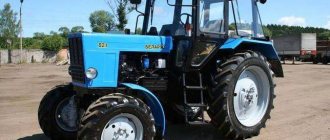
The mounted hydraulic system is designed to control and operate the MTZ-1221 Belarus tractor with mounted, semi-mounted and trailed agricultural machines and implements connected to the rear hitch.
The hydraulic system consists of controls, an oil tank with a filter, an oil pump, a two- or three-section flow distributor, a hydraulic lift and a hydraulic lift drive.
The hydraulic system controls (7), (8) (Fig. 36) are located in the tractor cabin, except for the pump activation handle (the design remains unchanged) and the additional position control handle (8a) (Fig. 36) located at the rear of the tractor on the hydraulic lift.
Control of external consumers - three handles of the flow distributor are located to the right of the steering wheel (the design remains unchanged). Handle positions (from bottom to top): “raise”, “neutral”, “lower” and “floating”.
Rice. 36. Hydraulic lift (monoblock) hydraulic system MTZ-1221 Belarus
1 — rear axle housing; 2 — plunger power cylinders; 3 - regulator-distributor; 4 — brackets; 5 — control cables for position (10) and power (11) levers; 6—adjustable travel limiter of the RHL; 7 — power control handle; 8 — position control handle; 8a - additional position control handle; 9 — right side control panel; 10 - position lever; 11 — power lever; 12 - body.
The power control handle (7) (Fig. 36) is located on the right control panel (9) first from the operator’s seat.
The range of its positions is indicated by numbers from “1” to “9”, which corresponds to the full range of plowing depth from minimum to maximum, respectively. The position control handle (8) (Fig. 36) is located next to the force control handle (7).
The range of its positions is indicated by the same numbers, which correspond to the positions of the hitch from the transport top position to the extreme bottom position, respectively.
An additional position control handle (8a) (Fig. 36) is located behind the tractor on a hydraulic lift; moving it toward you, if you stand behind the tractor, causes the rear linkage to rise, and away from you, to lower it.
The travel limiter of the rear linkage MTZ-1221 Belarus (6) is located in the groove of the right side console, in which the position control handle (8) moves.
The location of the oil tank, oil pump filter and distributor that controls external consumers is left unchanged.
The distributor is sectional, flow type, and has priority in control over the hydraulic lift.
Hydraulic lift
The hydraulic lift (Fig. 36) is installed on studs on the rear wall of the rear axle housing (1) and includes a control device and a regulator-distributor (3), built into a single housing (monoblock), carrying two single-acting plunger hydraulic cylinders (2).
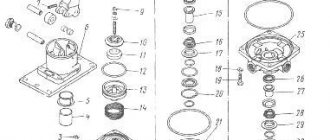
Rice. 37. Hydraulic lift device
1 - body; 2 — lever transmission of the force sensor; 3 - position sensor; 4 — shaft of rear linkage lifting arms; 5 — regulator-distributor; 6 - position lever; 7 — power lever; 8 - cover; 9 — lever transmission of the position sensor; 10 — lifting arms of the hitch; 11 — earring axis; 12 — power sensor earring; 13 - finger; 14 — power sensor rod; 15 - cover; 16 — adjusting shims for the power sensor spring; 17 — force sensor spring; 18 — washer; 19 — nut
The control device is mounted in the housing (1) (Fig. 37) and includes a position sensor in the form of a bracket attached to the shaft (4) of the rear linkage lifting arms (10); and a force sensor, including an earring (12) mounted on an axis (11) in the body (1) and connected by a pin (13) to the rod (14).
A spring (17) is installed on the rod (14), pressed by a nut (19). The position sensor (3) is connected to the position lever (6) through a system of levers (9). The pin (13) of the rod (14) is connected to the power lever (7) through a system of levers (2).
The control device operates as follows: when using the positional control method, the power lever (7) (Fig. 37) is installed in the extreme forward position along the tractor.
Subsequently, the linkage is controlled by the position lever (6) (Fig. 37) and the lever (7) through the cables (5) (Fig. 36). When moving the lever (6) back, the hitch rises, when moving it forward, it lowers.
This control process is carried out using a distributor regulator (5), built into the monoblock (1) and controlled by a position sensor (3).
When using the power control method, the position lever (6) is set to the extreme forward position along the tractor, which corresponds to the lower position of the lower links of the MTZ-1221.2 Belarus hitch.
The power lever (7) is set to the required plowing depth and then the regulation process is carried out by the built-in regulator-distributor (5), controlled by a power sensor.
By using the position handle (8) (Fig. 36) to limit the plowing depth when working with the power control method, mixed control is achieved.
The regulator-distributor (5), built into the monoblock (1), is a regulating element of the hydraulic lift and is a spool-valve device, with the help of which it is possible to obtain the positions “raise”, “lower”, “neutral” and automatic control of the RLL.
The hydraulic lift drive (Fig. 36) consists of a bracket (4) with power (7) and position (8) levers installed on it, which are connected through double-acting cables (5) to the position (10) and power (11) levers, respectively. The control handles are fixed with spring-loaded friction washers.
Are you looking for equipment or spare parts for it?
Figure 3 - MTZ electrical equipment diagram Can be used in forestry and public utilities, construction, and industry.
The performance of the gear pump and the capacity of the oil tank determine the possibility of activating stationary hydraulically driven units. The diesel engine meets all necessary requirements for exhaust gas emissions into the atmosphere.
It turned out to be in vain, the track is adjusted for row spacing of 70 cm, the front tires are 14.9R24, the rear tires are 18R38, they fit exactly between the plants, and due to the elongated base, they go between the rows very steadily. For example, in plowing, thanks to its good power reserve, it can easily replace the T Parking brake - disc, combined with service brakes, with a separate mechanical drive.
Ideal comfort allows the machine operator to perform the necessary actions during agricultural work. There are 9 of them at our enterprise, and the men who work for them all praise them. Power 44 kW. Power 44 kW.
Working with the MTZ-1221 Belarus hydraulic system
The hydraulic control system for the three-point rear linkage MTZ-1221-2 Belarus is equipped with a distributor-controller built into a monoblock, which ensures operation of the system in the following modes: power regulation; position control; mixed regulation.
The effective use of these modes depends on the machines being aggregated and agrotechnical conditions.
Position control
Provides precise and sensitive control of the position above the ground of connecting equipment such as sprayers, planners and others.
Position control can be used with tillage machines, semi-mounted plows with external cylinders, etc.
However, this type of regulation is not recommended for uneven fields.
Position control on a field with an uneven surface can cause constant jolts due to the rapid vertical movements of the attachment implement.
Force regulation
This is the most suitable mode for working with mounted or semi-mounted implements, the working parts of which are buried in the soil.
The system is sensitive to changes in traction force (caused by changes in soil resistance or tillage depth) through the center link of the linkage mechanism.
The hydraulic system responds to these changes by raising or lowering the implement to maintain the set traction force at a constant level.
The system responds to compression and tension forces in the central link, that is, it is a double-acting system.
Algorithm for setting the angle
Wash the inner cavity of the filter and the lid. Slowly press the lever on the stand and watching the arrow of the pressure gauge, determine the beginning of the rise of the MTZ injector needle. The engine has a sectioner. By slowly pressing the stand lever and observing the pressure gauge arrow, determine the pressure at which the MTZ injector needle begins to rise. The actual fuel consumption is calculated based on observations of the unit. Cleaning the coarse fuel filter of the MTZ Belarus engine Wash the coarse fuel filter by performing the following operations: — Turn off the fuel tank tap. Replace the fluoroplastic gasket with the screen gasket. In these clips you can more or less gauge the reaction of people to this or that law, or to the situation in the country or the world. After warming up the diesel engine, re-tighten the injector mounting bolts to a torque. Before installing them in the engine injector D, unpreserve the new nozzles by washing them in gasoline or heated diesel fuel. After all these steps, the hatch can be put in place. I am involved in farming 60 hectares of land. Adjusting valves MTZ 1221 engine D-260
Mounted hydraulic system control
The MTZ-1221.2 Belarus mounted hydraulic system is controlled by two handles located in the cabin on the right control panel: a power control handle; and position control handle.
Position control
Set the power control handle to the extreme forward position along the tractor.
Use the position adjustment handle to set the required height of the implement above the soil. The number “1” on the remote control corresponds to the transport position of the rear linkage, and the number “9” corresponds to the minimum height of the implement above the ground.
If it is necessary to limit the maximum lift height (for example, due to the possibility of damage to parts of the rear PTO), use the handle to set the maximum lift height and move the adjustable stop to it.
Force regulation
Use this adjustment method when working with mounted implements (ploughs, cultivators).
Move the power control handle to the extreme forward position along the tractor (number “9” on the remote control). Using the position adjustment handle, connect the implement to the MTZ-1221-2 Belarus hitch.
After entering the furrow, move the handle to the extreme forward position and use the handle to adjust the desired tillage depth.
When leaving and then entering the furrow (when plowing), use only the position control handle, without touching the power control handle.
If, due to uneven soil density, it is not possible to achieve a constant tillage depth, limit the maximum depth using the position control handle (mixed control mode), memorizing the corresponding number on the control panel.
Hydraulic linkage system based on an electro-hydraulic rear linkage control regulator
The tractor is equipped with two vertical hydraulic cylinders Ts 90x220 built into the hydraulic lift (without regulator), controlled by an electro-hydraulic regulator.
A schematic hydraulic diagram of a hydraulic system with an electro-hydraulic linkage control regulator is shown in Fig. 38.
Rice. 38. Hydraulic schematic diagram
1- hydraulic distributor RS 213 “Mita”; 2-electrohydraulic regulator ENR5-OS; 3-hydrocides Ts80x220; 4-pump NSh-32-3; 5-drain filter; 6 - quick-connect couplings.
The control functions of the MTZ-1221 Belarus rear linkage and the hydraulic working bodies of external consumers are implemented in a new hydraulic system (Fig. 39) due to the electro-hydraulic unit (3) mounted on the oil tank (1).
The lever control of the distributor (2) and the NSh-32-3 gear pump are similar for all variants of the hydraulic systems listed above.
Rice. 39. Housing of hydraulic units with assembled units
1-oil tank; 2-distributor control; 3-electrohydraulic unit (RS 213 “Mita” + adapter + ENR5); 4-pump NSh32-3; 5, 6-side terminals.
Rice. 40. Electrohydraulic unit
1-electrohydraulic regulator ENR5-OS; 2-adapter plate; 3-distributor RS 213 “Mita” (Finland).
The electrohydraulic unit (Fig. 40) consists of distribution sections of the RS213 “Mita” distributor, manufactured in Finland, electrohydraulic regulator ENR5-OS, manufactured (Germany) and an adapter plate (2) manufactured by MTZ.
The electro-hydraulic regulator ENR5-OS is controlled by two proportional magnets using an electronic hitch control system
Possible malfunctions and methods for eliminating them
Clean the control channel. The mounted machine in the raised position swings in the transverse direction above the norm. The tie rods of the MTZ tractor hitch are not adjusted correctly, MTZ - Adjust the tension of the tie bars. Check the operation of the unloading device and eliminate defects. In all cases, malfunctions are eliminated by replacing worn parts.
The distributor control lever is in the “Lift” position - Set the lever to the neutral position. Cold oil - Run the engine with the hydraulic pump turned on for min.
The spool filter is clogged and the working fluid does not flow into the booster device in sufficient quantities. The agricultural implement rises slowly There is not enough oil in the tank - Add oil.
The situation when the mounted unit does not lower can be eliminated in the following ways: cleaning the distribution valve; disassembling the distributor and cleaning the spool may jam due to clogging; increasing the oil temperature to 50 degrees.
Page last updated
Constant reduction in the speed of movement of the working body. Contamination of the working fluid.
Auto mode. If dirt cannot be removed in this way, then the distributor must be removed and sent to a repair shop. Hydraulics do not work on MTZ892
More on the topic: How to change the clutch on an MTZ-80
Replacing the oil filter of the MTZ-1221.2 Belarus hydraulic system
Subsequent replacements of the hydraulic system oil filter should be made every 1000 hours of operation.
- Remove the bolts, cover and remove the filter element assembly using the stopper.
- Remove the nuts, restrictor and filter element.
- Wash the housing in a cleaning solution.
- Install a new filter element and reassemble the filter by performing the operations in reverse order.
- Install the filter assembly into the hydraulic system tank, close it with the lid and secure with bolts.
Source
Checking and adjusting fuel injection pump D-260
An injector is considered to be in good working order if it sprays fuel in the form of a mist from all five holes of the nozzle, without any separate droplets flying out, continuous jets or thickenings.
Drain the oil into a suitable waste oil container. The tractor is allowed to run a distance, for example, in km, after which they monitor how much diesel fuel it used at a given distance. Fabric Wound Hose - This is a small diameter hose that is protected by an oil-resistant, durable fabric wrap that can effectively withstand elevated temperatures, humidity and fumes.
Final tightening torque
Tighten the injector mounting bolts evenly. During operation of the high-pressure fuel pump TNVD of the D engine of the MTZ tractor, when the main parts wear out, its adjustment parameters are violated.