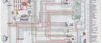
Before starting the engine using the ECU, turn on the instruments on the engine compartment panel with switch 9 Fig. The assessment of the starter condition may be incorrect if the voltage drop in all starting circuits exceeds the permissible value. The state of charge can be assessed by measuring the density of samples taken from the battery. With this voltage drop, the current shown by the ammeter should be recorded. Relay P1 is activated, contacts P1 through the turn signal switch connect the indicator lamps to the positive power supply terminal of the system. How to Read Car Wiring Diagrams
For measurements, you need an accurate voltmeter designed to measure low voltages. Based on the test results, the battery can be considered serviceable if the cell voltage is not lower than 1.5 V, i.e. It is turned on by the toggle switch on the left side.
Therefore, it is advisable to start checking by measuring the transition resistances in the places shown in Fig. The brake signal lights 6 are turned on by relay K4 of block 1. When you press the switch button 7, the indicator lamp of the light 9 should light up. When the measurement voltage is 24 V, the indicator lamp should light up, since transistor G4 is open to full excitation. Alarm. Device and principle of operation.
Engine cooling system diagram groove 4234
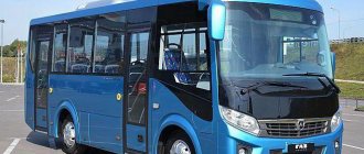
A striking representative of the PAZ 4234 is a modified bus model with index 3205. The manufacturer has improved the technical components. He has also increased the length of the body and increased the reliability of the vehicle.
In 2002, this version of the machine appeared on the market and was put into production line. And in 2007, the modification was finalized. The bus exists in this configuration to this day.
Power fuse block
The power fuse block is made in the form of high-power fuse links BPR-5-4, located in the battery box on the right side. May include additional conventional fuses on the left side of the block.
General scheme
- 90A Generator
- 40A Side lights
- 60A Fuse box, headlights, ignition
- 60A Fuse Box
- 20A ABS
- 25A Heater
- 10A Emergency mode
- 10A Battery box socket
Steering mechanism (UYAISH 453461.004-02) PAZ-3204 SHVGU-430/UYAISH 453461.004
Name:
Steering mechanism (UYAISH 453461.004-02) PAZ-3204
Spare parts for PAZ-3204
Contents: pcs
In our company you can buy original spare parts: steering mechanism (УЯИШ 453461.004-02) at a wholesale price of 88,800 rubles. Nomenclature number: SHVGU-430/UYAISH 453461.004. Or you can choose replacement options according to the code ШВГУ-430/УЯИШ 453461.004 with non-original spare parts or analogues from other manufacturers.
BALL SCREW HYDRAULIC BOOSTER SHVGU 430
The ball screw hydraulic booster SHVGU 430 is intended for use in steering systems of vehicles with a load on the steered axle of up to 5000 kg as a device that transmits and enhances the driver’s control action necessary to turn the steered wheels.
| SPECIFICATIONS | |
| Load on the steered axle of the vehicle, kN | up to 50 |
| Nominal torque on the bipod shaft, Nm | 4300 |
| Gear ratio | 17,4 |
| Nominal pressure of working fluid, MPa | 15 |
| Working fluid flow, dm3/min | 9..13 |
| Steering shaft speed | 4,8 |
| Bipod shaft rotation angle | 100/16′ |
| Rotation torque of the steering shaft at nominal pressure, Nm | 45 |
| Weight, kg | 35 |
- Buses of PJSC AK "Bogdan Motors" (Lutsk, Ukraine);
- Buses LLC "PAZ" (Pavlovo, Russia);
- Buses of the Republican Unitary Enterprise "Gomel Automobile Repair Plant" (Gomel, Belarus);
- Cars of JSC AMO "ZiL" (Moscow, Russia);
- "KAVZ LLC Buses" (Kurgan, Russia).
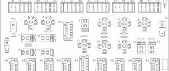
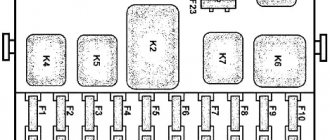
Fuse blocks
Located under the instrument panel.
Option 1
Characteristic of older models and consists of 2 sections
Scheme
| 1FU1 | 8A Passenger door drive control switch. Power supply for turn signal and door alarm systems |
| 1FU2 | 8A Power supply for driver's lamp switch, emergency switch |
| 1FU3 | 16A Power supply for devices, ABS unit, ignition system |
| 1FU4 | 8A Power supply for warning lamps, reversing light switch |
| 1FU5 | 8A Left wiper power supply |
| 1FU6 | 8A Circulation pump power supply |
| 1FU7 | 8A Power supply for windshield washer switch, instrument cluster and voltmeter |
| 1FU8 | 16A Power supply for fog lights |
| 1FU9 | 8A Power supply for side lights on the right side |
| 1FU10 | 8A Power supply for left side parking lights |
Specifications
When analyzing the main parameters of this model, it is advisable to mention that they can vary significantly and depend on the specific modification. It makes sense to study the most characteristic technical indicators, which are similar in most modifications of this model:
- the gross vehicle weight is 3225 kg;
- fuel tank volume 64 l;
- the design uses a single-plate clutch equipped with a hydraulic mechanism;
- Fuel consumption per 100 km averages 12.3 liters;
- tire size 175R16-185/175 R16 depending on the model;
- All modifications are equipped with a 5-speed manual transmission;
- The vehicle's carrying capacity is 965-970 kg.
This vehicle operates on a 4x2 wheelbase and is capable of carrying 12 passengers, not counting the driver. Thanks to its good cross-country ability, the model is often used as a suburban public transport.
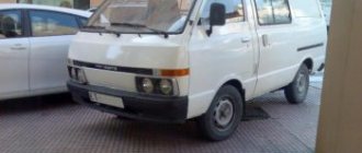
Pazik Photos
- Favorable cost of ownership
- Minimal maintenance costs
- Affordable price
- Air conditioner
- Luggage racks
- Various seat options
- Tinted double glazed windows
- Metallic body paint
- Electronic route indicators
- Ergonomic driver's workplace
- Efficient separate heating system for the workplace
Steering gear
Combined with power steering into one unit. The car's power steering reduces the force that must be applied to the steering wheel to turn the front wheels, softens the impacts that occur when the car moves on uneven roads, increases traffic safety, and allows you to maintain control over the direction of the car in the event of a front wheel tire break.
The steering mechanism has two working pairs: a screw with a nut on circulating balls and a piston and rack that engages with the toothed sector of the bipod shaft. The steering gear ratio is 20:1.
The steering gear housing is also a power steering cylinder in which the rack piston moves. The rack and sector teeth have a variable thickness along the length, which allows you to adjust the engagement gap by means of axial movement of the bipod shaft.
The axial position of the bipod shaft is set by an adjusting screw, the head of which fits into the shaft hole and rests on the washer. The axial movement of the adjusting screw relative to the bipod after assembly should be 0.02....0.08 mm. The bipod is installed on the shaft according to the marks.
Power steering zil-130-431410
Power fuse block
The power fuse block is made in the form of high-power fuse links BPR-5-4, located in the battery box on the right side. May include additional conventional fuses on the left side of the block.
General scheme
p, blockquote 8,0,0,0,0 —>
- 90A Generator
- 40A Side lights
- 60A Fuse box, headlights, ignition
- 60A Fuse Box
- 20A ABS
- 25A Heater
- 10A Emergency mode
- 10A Battery box socket
Summing up
As a result, we can say that the steering unit in a car is the main component of the entire mechanism. Do not postpone repair work and diagnostics if any deviations appear. At the slightest incomprehensible sound or vibration, you need to go to a service station and get a diagnosis done.
Installation of a steering column on a Gas car
Because this barely audible sound while the car is moving can turn into a big problem, especially if the Volga is driving at high speed along the highway.
vote
Article rating
Electrical circuit diagrams for the PAZ-32053 bus
The air supply to the brake mechanism is carried out by Fig.
A positive potential is formed at the emitter of transistor T1 relative to its base, and it closes. When the measurement voltage is 24 V, the test lamp should light up, since transistor G4 is open to full excitation. Checking other electrical appliances and equipment Electrical signal beeps.
Buses typically use acid-acid batteries. Trouble-free operation and accuracy of instrument readings can only be ensured if the electrical contacts are perfect, therefore, every time the instrument panel has been removed for any reason, the fastening of the instruments and wire fixing screws should be checked and, if necessary, tightened.
When the doors are opened, the switches automatically close the power supply circuit for the lights. The prescribed colors for them are clear, white or orange, only red is allowed at the back. Typically, the flashing frequency is 60 min-1; — the serviceability of the turn relay is checked by removing one lamp; if the flashing frequency does not change, the relay is faulty.
The sound signal and instrument lighting should be checked during regular maintenance. The generator is excited by the central switch through the charging indicator lamp, so a prerequisite is the constant serviceability of this lamp. In this way, not only the activation of the alarm is monitored, but also the serviceability of all lights.
The brake signal lights 6 are turned on by relay K4 of block 1. The assessment of the starter state may be incorrect if the voltage drop in all starting circuits exceeds the permissible limit.
Turn signal and hazard warning lights. Executive relay P1 is de-energized and its contacts are open. The voltage regulation of an alternating current generator, like that of a direct current generator, is carried out by regulating the excitation current. The protection circuit works as follows. The operation of the system is ensured by a unified contact-transistor relay-breaker.
Typically, a so-called load fork is used for measurements. Anti-lock brake system diagram on page This relay has two windings with one controlled contact pair. Sometimes it becomes necessary to turn the headlight in a vertical plane perpendicular to the direction of movement, since the reflected line delimiting the light and dark zones converges with the reference line on the screen at an angle. Basic principles of reading electrical diagrams in cars.