You can fix everything yourself.
KAMAZ trucks are equipped with a St-142b starter with a voltage of 24V and an idle current of up to 130 Amperes. To start it, you need to turn the key to a non-locking position. As soon as the start has taken place, the key is released.
Its action goes like this:
- The current from the batteries passing through the traction relay engages the flywheel ring gear and the drive gear while simultaneously closing the starter power contacts.
- rotation of the armature is created with transmission of torque to the flywheel through the drive gear.
- they are disconnected after the engine begins to operate in autonomous mode.
Troubleshooting in the KamAZ electric starting system
The engine starting system of a KamAZ vehicle can be in three alternative states: serviceable, operational and faulty (failure).
When in good condition, the starting system ensures the engine starts, and the condition of all devices meets the requirements of the technical specifications.
When in working order, the system ensures reliable engine starting, but the technical condition of some devices does not meet the technical conditions.
In the event of a malfunction (failure), starting the engine is impossible due to a malfunction of one or more system devices.
We will not consider the serviceable state of the system, since we are not tasked with determining the failure-free operation period of the system by the number of starts or by the mileage of the vehicle. To perform most tasks, it is enough to have the system in working order, when the system ensures reliable engine starting. Therefore, first of all, we will consider system failure and possible malfunctions, and indicate ways to quickly identify and eliminate them.
The system consists of seven devices, each of which affects the operation of the entire system. Therefore, in order to optimize the troubleshooting process, it is necessary to time each test and evaluate its impact on the performance of the starting system:
| rice. 1 |
Checking batteries
Remove the cover from the battery socket. By external inspection, check the condition of the terminals of the tips and the tightness of their fastening to the pole terminals (Fig. 1). Based on the density of the electrolyte, the degree of discharge of the battery should be determined. Check time is about 5 minutes;
Checking the presence of voltage on the ammeter
Unscrew the bolts securing the prior shield and tilt the shield towards you or place it on the steering column. In this case, free access to the ammeter leads is available. Connect a test light in series to the input and output of the ammeter. If the light on the “+” of the ammeter is on, then the circuit up to the ammeter is working, and vice versa. Then check the “-” ammeter. If the control lamp is on, it means that current is passing through the ammeter, and faults should be looked for further along the circuit. If the light does not light, then the ammeter is faulty. This test without replacing the ammeter takes up to 2 minutes;
Checking the instrument switch and starter
| rice. 2 |
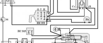
Before checking this device, it is necessary to carry out preparatory work to ensure access to the terminals. To do this, you need to remove the guard panel for the electric motors of the cabin heating system, unscrew the nut securing the instrument switch and starter and remove the device from the panel, leaving it on the wires (Fig. 2). Remove the red wire from the “AM” terminal and check the presence of voltage with a test lamp. If the lamp is on, it means that the circuit to the instrument switch and starter is working. Then you need to connect the red wire to the “AM” terminal, turn the key in the instrument and starter switch to the second position and check the “ST” terminal (green wire) with a light bulb. If the lamp is on, it means that the instrument and starter switch is working properly.
Starter Interlock Relay
This relay is installed under the hinged fuse panel. The relay is assembled on semiconductor devices and it is impossible to check it with a test lamp. A special device is used for checking. A malfunction of the starter interlock relay does not necessarily lead to loss of functionality of the starting system, so this test should not always be performed when troubleshooting;
Checking the starter relay
This relay is located under the hinged fuse panel. Use a wire to connect the “+” from the ammeter to the “K” terminal of the relay. In this case, you should hear a click when the contacts are turned on. In order to make sure that the contacts and relays are closed, it is necessary to connect a test lamp to terminal “C” of the starter activation relay (black wire). If the lamp is on, it means the relay contacts are closing.
Checking the starter traction relay
Use a wire to connect the “+” from the batteries to the terminal that pulls in the starter relay windings. If a click is heard, the relay is activated. The electric motor must rotate. If the starter motor does not rotate, use a test lamp to check for voltage at the contact bolt connected to the electric motor. If the lamp is on, it means that the starter traction relay is working normally.
Checking the starter motor
This check is the most time-consuming, since it is carried out (as a rule) with the starter removed. It takes 30 minutes to remove the starter and 25 minutes to diagnose.
Since the electric starting system has a small number of elements (only seven), the method of element-by-element testing is used, or sequentially dividing the system into two subsystems.
autoruk.ru
General information about the starting system
The electrical wiring on KAMAZ is a rather complex system, and the starter in it is, in fact, an electric motor equipped with a traction relay. You can also find out on our website who needs a KAMAZ 5320 wiring diagram and why
- It is located on the flywheel housing on the driver's side.
- Fastens with 3 bolts and a stud.
- The series starter electric motor operates on direct current .
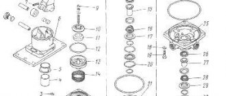
Starter design
In addition to the housing itself, it contains the following components:
- anchor,
- excitation winding,
- brush and commutator,
- drive shaft,
- two covers (front and back).
The device body acts as a magnetic circuit with cores attached to it. The front starter cover directly covers the drive mechanism, while the rear cover covers the assembly with brushes and commutators. A rectangular copper wire is used in the excitation winding .
One end of it goes to the insulated terminal of the housing, the other to the positive brushes. The winding turns are insulated using impregnated cable paper.
Basic elements of the starting device
Where is the starter relay located on KAMAZ?
Kamaz repair
How to check, connect the signal, ignition, starter relay......
Kamaz 2 repair
Long-range. We are starting KamAZ after 6 months of inactivity. Relay repair. Bad mass
Kamaz. Repair.
Starter relay
How to connect a 4- and 5-pin relay. Why?
How to remove the starter on a Kamaz car (Theory)
The starter does not work. The starter does not turn. The starter relay does not retract.
Starter connection diagram
Also see:
- Power of KAMAZ 740
- Where is the candle at KAMAZ
- Repair of Euro KAMAZ shaft
- Tank capacity KAMAZ 55102
- Control fuel consumption of a KAMAZ 6520 vehicle
- Dismantling the KAMAZ compressor
- Pre-launch device for KAMAZ
- KAMAZ days of downtime
- KAMAZ shock absorbers for UAZ
- A number of KAMAZ models
- How to rebuild a KAMAZ engine video
- KAMAZ trucks from state storage
- Truck crane ks 35714 KAMAZ
- Fuel equipment bosch KAMAZ euro 4
- Semiconductor diode KAMAZ
Home » Clips » Where is the starter relay on a KAMAZ
kamaz136.ru
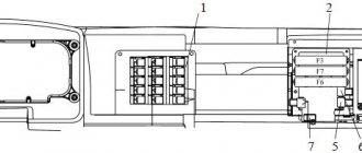
Fuses and relays for vehicles with Euro-4 class engines
Location of fuses and relays
1 – Relay behind the switch panel; 2 – fuse block (F2, F3, F4, F6); 3 – relay block; 4 – fuse F1; 5 – starter relay; 6 – alarm relay; 7 – windshield wiper relay; 8 – turn signal interrupter relay.
- Relay behind switch panel
- 1, 2, 3, 4 – See the Table of applied relays; 5- fuel heating relay; 6 – ECU relay; 7 – relay for daytime running lights; 8 – platform stop sensor relay; 9 – rear fog lamp relay; 10 – oil separator relay
- Table of relays used
Operating principle of the starter blocking relay on KAMAZ
How to connect a 4- and 5-pin relay. Why?
Kamaz 2 repair
Starter Interlock Relay
Starter solenoid relay
Installing an additional starter relay on a VAZ 2112
VEHICLE ELECTRICAL EQUIPMENT.
Installation of Pantera CL 500 alarm system on VAZ 2104, 2105, 2107 (part 3)
3. Charging system - 2
12 to 24 in the MTZ tractor. Standard wiring 12.
Starting modified engine PDM for T 150, DT 75 with a starter from KAMAZ
Also see:
- Gear ratio of KAMAZ winch
- Side view of KAMAZ
- KAMAZ rear fender holder
- KAMAZ pumping oil seal block
- How to determine the KAMAZ model
- KAMAZ onboard 65117 with fassi f 155 0 22
- KAMAZ 6520 average axle play
- Fuel tank 175 l for KAMAZ
- Tire pressure KAMAZ 5350
- Engine KAMAZ 740 power
- How to change a KAMAZ kingpin
- KAMAZ 53229 rear gearbox
- How to remove the KAMAZ 740 starter
- Side view mirror KAMAZ 65115
- Purpose of the KAMAZ 740 diesel engine power system
Home » New » Operating principle of the starter blocking relay on KAMAZ
kamaz136.ru
Specifications
Starter technical parameters:
| Rated voltage, V | 26 |
| Mechanism power | 10.5 l. With. |
| Voltage required to turn on the traction mechanism relay, V | Pull-in winding - 8 Holding winding - 5 |
| Minimum brush height, cm | 1,3 |
| Brush spring pressure, kgf | From 1.75 to 2.06 |
| Maximum number of armature revolutions | 6400 |
| Maximum no-load current, A | 150 |
| Battery capacity | 190 Ah |
| Direction of rotation of mechanisms | Right |
| Drive gear | Eat |
| Number of teeth | 10 |
| Gear module, mm | 3,75 |
| The angle at which the teeth are located | 20° |
| Weight, kg | 24.7 thousand |
| Brushes tension force, N | From 10 to 14 |
| Voltage during idling, V | 12 |
| Wire cross-section, mm | 2,26*3,53 |
| Number of poles | 4 |
| Number of turns on coils | 8 |
| Shaft speed | At least 4 thousand revolutions per minute |
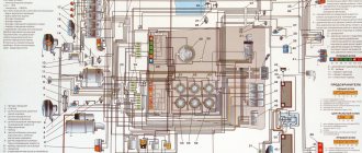
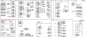
Colored electrical diagram of KamAZ-5320 with description
The designers especially focused their attention on the problem of reliability and fastening of devices and components. There are the following features of car wiring in external light alarm:
- Special interlocks are used to ensure that electrical circuits do not fail. For example, a relay prevents the ground from turning off while the car’s engine is running.
- The interior heating structure and the driver's seating system have been carefully thought out by the developers.
- Double square headlights, which can be very often found nowadays on official vehicles, are also installed.
- A device generating energy - G-272 - was installed on the power apparatus. The generator includes the following elements:
- synchronous 12-pole three-phase electrical unit;
- direct-flow ventilation system;
- built-in rectifier unit.
The above device operates in a single-wire structure. It has several conclusions:
- Negative - it joins the base (mass).
- The positive one is connected to the battery.
- The “Ш” terminal is necessary to connect the voltage system.
It is important to note that incorrectly connecting the base to the positive terminal of the battery, as a rule, leads to the destruction of the voltage system and the diodes that are located inside the generator.
The main symptoms of a malfunctioning starter
To determine possible starter malfunctions, you will have to pay attention to its behavior, as well as the sounds it makes.
- So, if the traction relay is activated, but the crankshaft does not turn, let's start by checking the battery charge. The reason may be that the brushes or commutator are clogged with dirt and dust. In this case, the traction relay itself may have burnt or oxidized contacts.
- After the engine starts, the starter armature may continue to rotate. This may mean that the relay springs are broken and need to be replaced with new ones. Welding of the contact disc to the bolts may occur. In this case, we will need a KAMAZ wiring diagram in order to clean the disk itself and the bolts, or replace them. If necessary, the starter interlock relay may need to be replaced.
- Another situation is that when you try to start, characteristic clicks are observed that the traction relay makes. In this case, you need to start by checking the contact connections in the circuit of the relay itself and restoring the reliability of the contacts. If necessary, it may be necessary to replace the retractor itself.
Note! There may be no contact between the brushes and the commutator, in which case either the brushes themselves or their springs are replaced.
- If the wiring on the KAMAZ was assembled with a violation of the contact adjustment at the moment of closing, turning on the starter will be accompanied by the grinding of the drive gear. You will need to adjust the gap between the thrust washer and the gear. When you try to start the engine, gears may grind, but the engine will not start.
We visually check the condition of the contacts and wiring harnesses.
This means that the issue may be an incorrectly adjusted moment of closing the contacts of the traction relay . Or the ends of the teeth of the flywheel gear or drive are clogged. In this case, you will have to either replace the gears with new ones or try to restore the teeth. They are reanimated by surfacing.
Tip: At a minimum, try to smooth out any rough spots on them first.
It is possible that the armature continues to rotate, but the crankshaft does not rotate, which means that there is no interaction between them. First of all, check that the starter is adjusted correctly. After this, make sure that the teeth of the drive gears and the flywheel ring are in unworn condition.
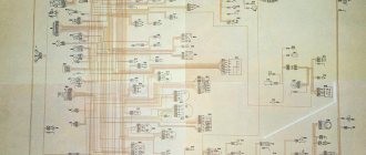
Fuse diagram KamAZ-5320
On vehicles of the popular KamAZ modification, a single-wire connection structure is used. The negative output of the main energy sources and a certain number of consumers is output to the mass of the machine. The base usually serves as the 2nd wire.
The relatively low-voltage wires of the PGVA model used have different cross-sections (from 1 to 50 mm2), their choice depends on the power of the consumers, mechanical strength and voltage drop indicators. To connect the mass of the cabin to the frame of the machine, a braided wire made of AMG-16 aluminum is used.
To connect the wires to each other and connect them to devices in the electrical equipment system, the former have plugs. The latter are installed in pads; they are not afraid of corrosion and various mechanical damages. When installing electrical wiring, a special lubricant is applied to the plugs.
Be sure to check the strength of the connections between the plugs; do not allow the special tongue of these elements to break. When installing the latter in the blocks, it is worth remembering to match the colors of the wires that are connected to each other.