On vehicles with a 6×4 wheel arrangement KamAZ-53215, KamAZ-65115 and their modifications, middle and rear axles with a central two-stage final drive are installed. The design of the rear and middle axles is similar, the difference lies in the installation on the middle axle of a center locking differential and individual original parts mating with it.
- Maintenance of KamAZ 65115, 53215 bridges
- Repair of bridges KamAZ 65115, 53215
Depending on the purpose or operating conditions of various vehicle modifications, their KamAZ drive axles differ from each other:
- final drive ratio (7.22; 6.53; 5.94; 5.43)
- the presence of a cross-axle differential lock;
- flanges for fastening cardan shafts;
- axle housing depending on the vehicle's load capacity;
- axle shafts;
- brake mechanisms (automatic or non-automatic adjustment levers, the presence of ABS, brake lining material, size and type of brake chambers, etc.).
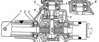
In Fig. 428 shows a cross-section of the rear and middle drive axles of the KamAZ-53229 vehicle.
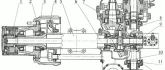
The KamAZ drive axle consists of an axle housing 7 with suspension elements, a main gear 10, axle shafts 8, a hub with a brake drum 1 and brake mechanisms 16.
The KamAZ 7 axle crankcase (Fig. 428) consists of two stamped beams welded together, a crankcase flange 12 is welded on top, and a crankcase cover 14 is welded on the bottom. To the ends of the beam, its cross-section from rectangular goes into an annular one, where axles 2 are welded by friction welding. for installing wheel hubs on bearings 18 and 20.
Axle shafts of the unloaded type are made for KamAZ 53229, KamAZ 65115 from 40ХН2МА steel, and for KamAZ 53215 from 50GF steel and have a different appearance (Fig. 430). The right and left axle shafts differ in length. The surface of the axle shafts is hardened along the entire length with heating. h. The flange of the axle shaft has two threaded holes M12x1.25, designed to facilitate its dismantling. The main gear (Fig. 431) is two-stage and consists of a gearbox housing, a pair of spiral bevel gears and a pair of helical spur gears. The design of the main gear makes it possible to obtain 4 gear ratios by changing the number of teeth of only a cylindrical pair of gears without changing other parts.
Vehicles of the KamAZ family are equipped with a symmetrical, geared, conical cross-axle differential. The interwheel differential (Fig. 432) consists of the right 23 and left 26 cups, a cross 15, four satellites 17 and two side gears 24.
The center differential (Fig. 431) is designed to distribute torque between the rear and middle axles, as well as to prevent power circulation between the drive axles when driving on paved roads (in the presence of kinematic mismatch between the axles or when there is a significant difference between their rolling radii driving wheels).
Rice. 428 Drive axle: 1 — hub with brake drum; 2 - axle; 3 - cuff; 4 - ring; 5 — caliper mounting flange; 6- spring support; 7 — axle housing; 8 — axle shaft; 9 — safety valve; 10 — main gear; 11 — nut securing the main gear; 12 — axle housing support flange; 13 — magnetic plug; 14 - axle housing cover; 15 — reaction rod lever; 16 — brake mechanisms; 17 — ring gear of the ABS rotor; 18, 20 — tapered roller bearing; 19 — wheel rim mounting bolt; 21 — axle shaft gasket; 22 — nut securing the axle shaft
Rice. 430 View of the axle flange
Bridges 53215, 65115. KamAZ vehicle transmission units
1 Design of drive axles 53215, 65115
On vehicles with a 6×4 wheel arrangement KamAZ-53215, KamAZ-65115 and their modifications, middle and rear axles with a central two-stage final drive are installed. The design of the rear and middle axles is similar, the difference lies in the installation on the middle axle of a center locking differential and individual original parts mating with it.
Depending on the purpose or operating conditions of various vehicle modifications, their drive axles differ from each other:
- final drive ratio (7.22; 6.53; 5.94; 5.43)
- the presence of a cross-axle differential lock;
- flanges for fastening cardan shafts;
- axle housing depending on the vehicle’s load capacity;
- axle shafts;
-brake mechanisms (automatic or non-automatic adjustment levers, the presence of ABS, brake lining material, size and type of brake chambers, etc.).
In Fig. 428 shows a cross-section of the rear and middle drive axles of the KamAZ-53229 vehicle.
Rice. 428 Leading bridge
1 — hub with brake drum; 2 - axle; 3 - cuff; 4 - ring; 5 — caliper mounting flange; 6-spring support; 7 — axle housing; 8 — axle shaft; 9 — safety valve; 10 — main gear; 11 — nut securing the main gear; 12 — axle housing support flange; 13 — magnetic plug; 14 - axle housing cover; 15 — reaction rod lever; 16 — brake mechanisms; 17 — ring gear of the ABS rotor; 18, 20 — tapered roller bearing; 19 — wheel rim mounting bolt; 21 — axle shaft gasket; 22 — nut securing the axle shaft
The drive axle consists of an axle housing 7 with suspension elements, a main gear 10, axle shafts 8, a hub with a brake drum 1 and brake mechanisms 16.
Bridge housing
7 consists of two stamped beams welded to each other, with a welded crankcase flange 12 on top, and a crankcase cover 14 on the bottom. To the ends of the beam, its cross-section goes from rectangular to annular, where axles 2 are welded by friction welding, intended for installing wheel hubs on bearings 18 and 20. From the outer cylindrical surface at each end of the beam, flanges 5 are welded, intended for installing wheel brake calipers with pads. The cross-section of the beams in the areas under the springs is rectangular. In the middle part, the beam is widened and forms a so-called “banjo” to allow installation of the main gear.
The axle housing of KamAZ-53215, 54115 vehicles has a wall thickness of 11 mm, the axle housing of KamAZ-53229, 65115 vehicles has a wall thickness of 14 mm. The rear axle housing is not interchangeable with the middle axle housing along the reaction rod arms (item 15, Fig. 428).
Before installing bearings 18 and 20, ring 4 of cuff 3 is pressed onto the axle 2. The inner ring of the bearing 20 is mounted on the axle with a sliding fit, and the outer ring is pressed into the annular recess of the hub 1. To prevent lubricant from leaking out of the hub cavity, a cuff is pressed into it from the inside 3. The hub assembly with the cuff, bearings 18 and the outer ring of the bearing 20 is installed on the axle.
After this (Fig. 429), the inner ring with the bearing rollers is mounted on it, the lock washer 5 and the bend washer 3 are put on, and a special bearing nut 1 is screwed on, which regulates the axial clearance of the hub bearings. It is fixed in a given position by a lock washer 5, the tendril of which fits into the groove of the trunnion, and into one of the holes there is a spherical extrusion on the bend washer 3. From unscrewing, the nut 1 is locked by bending it onto the edge of the bend washer.
To prevent lubricant from flowing from the main gear cavity to the hub cavity, a lip seal is installed, containing a lip seal 2, a spacer ring 4 and a plug 6 in the axle groove.
Rice. 429 Seal of the hub bearing mounting
1 — bearing nut; 2 - cuff; 3 — folding washer; 4 — spacer ring; 5 — lock washer; 6 - plug
Axle shaft 8 is attached to wheel hub 1 (Fig. 428) on studs. Conical expansion bushings are put on the studs. The rear suspension installation parts are welded to the axle housing: on top of both ends of the rear spring support 6, on the bottom - the levers 15 of the rear suspension reaction rods. A safety valve 9 is provided for ventilation of the crankcase cavity, and a magnetic plug 13 is provided for draining the lubricant.
Half shafts
unloaded type are made for KamAZ 53229, KamAZ 65115 from 40ХН2МА steel, and for KamAZ 53215 from 50GF steel and have a different appearance (Fig. 430). The right and left axle shafts differ in length. The surface of the axle shafts is hardened along the entire length with heating. h. The flange of the axle shaft has two threaded holes M12x1.25, designed to facilitate its dismantling.
Rice. 430 View of the axle flange
main gear
(Fig. 431) - two-stage, consists of a gearbox housing, a pair of spiral bevel gears and a pair of helical spur gears. The design of the main gear makes it possible to obtain 4 gear ratios by changing the number of teeth of only a cylindrical pair of gears without changing other parts.
Gear housing
The 12 middle and rear axles are cast from high-strength cast iron, are structurally identical and are mounted on top of the axle beams using studs, four of which are equipped with conical expansion bushings.
Drive bevel gear
10 of the rear axle differs from the bevel gear of the middle axle 29 in the length of the hub. Gears are made of high quality alloy steel. Each gear has a hole. At the same time, for the middle axle gear it is cylindrical, designed to ensure the passage of the rear axle drive shaft 31, while for the rear axle gear it is splined, designed for connection with the drive shaft 11. The gears are installed in the gearbox housing on two tapered bearings 7 and 9. The rear and rear axle bearings The middle axles are interchangeable, but the gear set for each axle is original.
Table 60 Main gear ratios depending on the number of gear teeth in a cylindrical pair
Rear axle drive bevel gear
is pressed onto shaft 11, and together with the shaft is installed on two supports. One support is the tapered bearings 7 and 9 of the drive bevel gear, the other is the cylindrical roller bearing 13, installed in the crankcase bore at the rear end of the shaft. The inner ring of bearing 9 is pressed onto the gear neck, and the outer ring along the sliding fit is installed in the crankcase bore. The outer ring of the bearing 7 is pressed into the seat of the cup 5, and the inner ring is mounted on the sliding landing on the gear neck. A support washer and an adjusting sleeve 8 are installed between the bearings, designed to adjust the preload of the bearings. The bearings are secured against axial displacement by a support washer 2, which rests against the end of the flange 1. The flange, in turn, is fixed on the shaft 11 with a nut 15. The flange is interchangeable with the rear flange of the middle axle.
The axial forces generated during operation of the main gear are absorbed by tapered bearings and transmitted to the crankcase. To ensure the supply and removal of lubricant to the bearings, longitudinal and radial channels are provided in the crankcase and sleeve. To prevent lubricant from leaking out of the gearbox cavity, a cuff is pressed into the bearing cover 3, and a dirt deflector is welded to the flange to prevent dirt from entering.
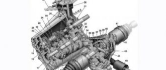
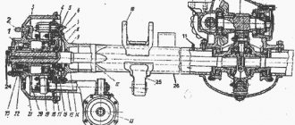
Rice. 431 Main transmission of rear and intermediate axles (longitudinal section)
1. 44 — drive flange; 2 — washer; 3, 33, 45 — bearing cover with cuff; 4 - gasket; 5, 27 — bearing cup; 6 — adjusting gaskets; 7, 9 — tapered roller bearing; 8 — adjusting sleeve; 10, 29 — bevel gear; 11 — drive shaft; 12 — gear housing; 13 — radial roller bearing; 14 — rear shaft cover; 15, 43 — flange mounting nut; 16 — cover gasket; 17 — center differential housing; 18 — front cup; 19 — rear axle drive gear; 20 — satellite center differential; 21 — crosspiece of the center differential; 22 — control sensor for turning on the center differential; 23 — rod of the locking mechanism; 24 — locking fork; 25, 30 — filler plug; 26 — locking clutch; 28 — drive mechanism for locking the center differential; 31 — rear axle drive shaft; 32, 46 — ball bearing; 34 — bearing fastening nut; 35 — lock washer; 36 — lock washer; 37 — locknut for fastening bearings; 38 — half-clutch locking center differential; 39 — middle axle drive gear; 40 — rear center differential cup; 41 — support washer; 42 — self-locking bolt
Rice. 432 Main transmission of rear and intermediate axles (cross section)
1 — gear housing; 2 — radial roller bearing; 3 — driven bevel gear; 4 - key; 5 — cylindrical drive gear; 6, 8, 19 — tapered roller bearing; 7 — adjusting sleeve; 9 — adjusting gaskets; 10 — cup of bearings; 11 - gasket; 12 —
bearing cover; 13 — support washer; 14 — bearing fastening nut; 15 — crosspiece of cross-axle differential; 16 — satellite support washer; 17 — satellite; 18 — adjusting nut; 20 — support washer for the semi-axial gear; 21 — stopper; 22 — differential bearing cover; 23, 26 — differential cup; 24 — semi-axial gear; 25 — cylindrical driven gear; 27 — cross-axle differential locking coupling
Drive bevel gear of the middle bridge
29 is mounted on two tapered bearings 7 and 9. The inner ring of bearing 9 is pressed onto the gear neck. The outer ring on the sliding fit is installed in the crankcase socket. The outer ring of bearing 7 is pressed into the seat of the cup 27. The middle axle bearing cup is not interchangeable with the rear axle cup. The inner ring of the bearing 7 is mounted on the gear journal according to the sliding fit. An adjusting spacer sleeve 8 is installed between the bearings, designed to adjust the bearing preload. The inner ring against axial movement is fixed with a special nut 34, screwed onto the threaded part of the gear. The nut pin fits into one of the holes of the lock washer 35, which is prevented from turning by a tendril that fits into the groove of the gear. The washer is locked with a lock nut 37. A locking plate 36 is installed between the washer 35 and the lock nut 37. The axial forces generated during operation of the transmission are absorbed by tapered bearings and transmitted to the crankcase. To ensure the supply and removal of lubricant to the bearings, longitudinal and radial channels are provided in the crankcase and sleeve. The bearing housing 27 is attached to the gearbox housing 12 with bolts, and the center differential housing 17 is, in turn, attached to the bearing housing.
Rear shaft
31 of the middle axle is designed to transmit torque to the rear axle. It is mounted on two supports: one support is the ball bearing 45 of the center differential cup, and the rear support is the ball bearing 32, installed in the socket of the gearbox housing. The ends of the shaft are splined. One end fits into the hole of the gear 19 of the center differential of the rear axle drive, and on the other end, flange 1 is installed until it stops in the inner ring of bearing 32, fixed on the shaft with a nut 15. To prevent lubricant leakage and dust and dirt from entering the bearing cover 33, a cuff is pressed into the bearing cover 33. and a dirt deflector is welded to flange 1. The flange is interchangeable with the drive flange of the rear axle. To ensure bearing lubrication, a longitudinal channel is provided in the crankcase.
The remaining elements of the main drive of the rear and middle axles, with the exception of the center differential installed only on the middle axle, have no structural differences.
Driven bevel helical gear
3 (Fig. 432) is pressed onto the neck of the drive cylindrical gear 5 until it stops and is additionally secured against rotation by a key 4.
Drive spur gear
5 (Fig. 432), assembled with the driven bevel gear 3, is installed on two supports in the sockets of the gearbox housing 1. The front support is a cylindrical roller bearing 2, the inner ring of which is installed on the gear neck, and the outer ring in the crankcase socket. The rear support is made up of two tapered roller bearings 6 and 8, the inner rings of which are installed on the shaft journals, and the outer rings are installed in the bearing housing 10. The bearing preload is adjusted using the adjusting sleeve 7.
The inner ring of the outer bearing 8 rests on the support washer 13 and both bearings are fixed on the shaft of the drive spur gear with a nut 14, screwed and cored on the threaded end of the shaft. To prevent the nut from loosening itself, the support washer has two special antennae that fit into the grooves of the shaft. To ensure adjustment of the engagement of the bevel gear pair, when installing the bearing cup 10, a set of adjusting shims 9 is installed between the cup and the crankcase. After installation and adjustment, the bearing cup of the drive cylindrical and driven bevel gears is closed from the outside with a cover 12 cast from an aluminum alloy.
The axial forces arising during the operation of the main gear are perceived by two tapered bearings 6 and 8. To unload the bearings when moving in reverse, the inclination of the teeth of the cylindrical pair is selected so that the axial force arising from the operation of the cylindrical pair is directed towards the force directed from the conical couples, and partially compensated for it.
The axial force directed towards the bevel bearings is transmitted from the driven bevel gear to the end of the teeth of the drive cylindrical gear and then through the inner ring of the bearing 6, to the rollers, and the outer ring of the bearing, to the bearing housing and through the bolts to the gearbox housing.
The axial force acting on the drive cylindrical gear towards the cylindrical roller bearing is transmitted to the nut 14 and through the support washer 13, the inner ring of the bearing 8, the rollers, the outer ring of the bearing, and the bearing cup to the gear housing.
Driven spur gear
25 helical. The gear assembly with the differential on two tapered bearings 19 is installed in the gearbox housing. The gear is installed on the differential cups 23 and 26 in a sliding fit and is attached to them with bolts and self-locking nuts.
Vehicles of the KamAZ family are equipped with a symmetrical, geared, conical cross-axle differential.
Interwheel differential
(Fig. 432) consists of the right 23 and left 26 cups, a cross 15, four satellites 17 and two semi-axial gears 24.
The differential cups are processed as an assembly and branded with the serial number of the kit. The material of the cups is high-strength cast iron. The cups have holes bored out for installing crosspieces and semi-axial gears.
The differential satellites on bronze bushings are mounted on a crosspiece, which, in turn, is installed in the sockets of the differential cups. To prevent wear, support steel washers 16 are installed between the surfaces of the differential cups and the ends of the satellites.
The side gears 24 are installed in holes bored into the differential cups. Between the end of the rear part of the gear and the differential cup, to prevent wear of the latter, a steel support washer 20 is installed, which has ball grooves on one side. The washers must be installed with the ball grooves facing the gears.
Adjustment of the preload of bearings 19 is carried out using adjusting nuts 18, which have grooves, into one of which, after adjusting the differential bearings, the stopper antenna 21 enters.
The differential bearing covers are attached to the gearbox housing with two bolts 2 (Fig. 433), under the head of which support washers 1 are installed. To prevent the bolts from unscrewing, they are secured with wire or locking washers 3 and lock washers 4, which are secured from falling out with cotter pins 5. To ensure correct To align the bearing cover with the gearbox housing, two pins are pressed into it, which are installed during joint machining.
Rice. 433 Locking the cross-axle differential bearing cover bolts
1 — support washer; 2 — bolt for fastening the bearing cover; 3 — lock washer; 4 — lock washer; 5 - cotter pin; 6 - wire
To improve the vehicle's cross-country ability in poor road conditions (ice, mud, etc.), the cross-wheel differential can be equipped with a locking mechanism.
The housings of drive axles that have a cross-axle differential lock (see Fig. 434) contain an activation mechanism, including a locking fork 3 with nuts installed in it, a push rod 11, onto which a piston 9 is screwed and locked from turning with a nut, and a diaphragm 8, which closes cover 7. The locking fork is installed on the bracket console 6 and returns to its original position when turned off by return spring 4.
Rice. 434 Cross-axle differential locking mechanism
1 — half-clutch locking on the axle shaft; 2 — half-clutch locking on the differential cup; 3 — locking fork; 4 — return spring; 5 — axle housing flange; 6 — locking fork bracket; 7 - cover; 8 - diaphragm; 9 - piston; 10 — control sensor for locking; 11 - rod
To provide remote control of the inter-axle locking mechanism, there is a special button in the driver’s cabin on the switch panel, and on the instrument panel in the control lamp block there are signal lamps indicating that the rear and intermediate axles are locked.
When the key is turned on, an electrical signal is sent to the electro-pneumatic valve installed on the car frame, which opens and passes compressed air to the locking mechanism chamber. After this, when the half-coupling halves of the axle shaft and the differential cup are connected, a warning light on the instrument panel in the driver's cabin lights up and a buzzer sounds, signaling that the cross-axle differential lock is engaged.
When the cross-axle differential lock is turned off, the valve closes and the air from the locking mechanism chamber is released into the atmosphere. The indicator lamp should go out and the buzzer will turn off.
Operation of the cross-axle differential and drive.
To prevent the circulation of parasitic power, reduce tire wear and optimally distribute torque between the right and left wheels when driving on dry paved roads, the cross-axle differential lock must be turned off. The cavity of the locking mechanism is exposed to the atmosphere. The rod of the locking mechanism 11 (Fig. 434) with the movable piston 9, under the action of the return spring 4, is in its extreme position and rests against the diaphragm 8. The locking coupling halves 1 and 2 are open.
With the same resistance on the drive axles and the same rolling radii of the wheels, the rotation speeds of the axle shafts of the right and left wheels are equal. In this case, the satellites do not rotate relative to the cross. The differential works as one unit.
If there is a kinematic mismatch caused by a change in the radius of the wheels, uneven tire wear or other reasons, the rotation speeds of the axle shafts become unequal. At the same time, the satellites rotate relative to the crosspiece and prevent the circulation of parasitic power.
When driving on slippery or wet dirt roads, the differential is blocked to prevent one of the wheels from slipping. The differential is locked when parked or when driving slowly by pressing a special key. In this case, an electrical signal is sent to the electro-pneumatic valve installed on the frame of the car, which opens and passes compressed air into the chamber of the locking mechanism, moving the piston 9 with the rod 11. The rod 11 acts on the locking fork 3, which moves the movable locking clutch 1 on the axle shaft until it connects with the clutch 2, located on the differential cup. After this, in the driver’s cabin on the instrument panel in the control lamp block, a lamp lights up, indicating that the cross-axle differential lock is on.
The inter-wheel differential is locked and works as one unit, preventing wheel slipping.
Center differential
(Fig. 431) is designed to distribute torque between the rear and middle axles, as well as to prevent power circulation between the drive axles when driving on paved roads (in the presence of kinematic mismatch between the axles or when there is a significant difference between the rolling radii of their drive wheels ).
On KamAZ-53229, KamAZ-65115 vehicles and their modifications, a symmetrical, lockable, geared bevel center differential is installed.
The differential consists of a differential housing 17 left 18 and right 40 cups, four satellites 20, a spider 21, a middle axle drive gear 39, a rear axle drive gear 19, a ball bearing 46, a bearing cap 45 and a flange 44.
In the upper part of the crankcase there are holes for installing the differential lock mechanism 28.
Differential cups 18 and 40 are connected to each other by self-locking bolts 42. In each cup, surfaces are machined for satellite support washers and bevel gears, and also holes are bored for installing rear axle drive gear 19 in the front cup 18, and middle drive gears 39 in the rear cup 40. bridge. The assembled cups have holes bored out for installing the differential crosspiece 21. To ensure the supply of lubricant to the rubbing surfaces, three inclined holes are drilled in each cup. The rear cup ends with a cylindrical neck with a gear ring cut on it, designed to ensure locking of the center differential. On the neck of the front cup there are rectangular slots cut for installing the drive flange 44. The flange is fixed on the neck with a nut 43.
The differential satellites 20 are mounted on spider spikes on bronze bushings. To prevent wear of the differential cups, steel support washers with special ball recesses are installed between the back of the gears and the cups to create the necessary supply of lubricant.
The middle axle drive gear 39 is installed in the rear differential cup. To ensure running-in and reduce wear, the gear is phosphated. To prevent cup wear, a steel support washer is installed between the rear end of the teeth and the cup.
The rear axle drive gear 19 is installed in the front differential cup. The outer cylindrical surface of the gear journal is machined and designed for installation in the front differential cup. The gear has a splined hole designed for connection with the splined end of the through shaft 31 of the rear axle drive.
The differential assembly is mounted on two supports, one of which is a ball bearing 46 installed in the differential housing socket, and the other is the cylindrical surface of the middle axle drive bevel gear 29 installed in the gearbox housing on two bevel bearings. The axial forces arising during the operation of the transmission are absorbed by the ball bearing 46. To prevent lubricant leakage from the center differential housing, a cuff is pressed into the bearing cover 45, and to prevent the ingress of dust and dirt, a dirt deflector is welded to the flange.
The center differential locking mechanism 28 is installed in the upper part of the center differential housing. It is designed to forcefully lock the differential when driving on slippery and wet dirt roads. Attach to the housing 17 of the center differential with two bolts. On the rod 23 of the locking mechanism there is a clutch fork 24, which with its claws fits into the annular groove of the locking clutch 26.
The locking clutch has an internal spline hole designed to lock the rear differential cup and clutch 38 of the middle axle drive gear. The middle axle drive gear clutch has a splined hole inside to ensure installation on the gear, and on the outside there are two rings cut with which it engages with the splined hole of the locking clutch.
To ensure remote activation of the locking mechanism in the driver's cabin, on the right side of the steering wheel, a tap for the locking mechanism is installed on the instrument panel, and in the control lamp block there is a signal lamp indicating the activation of the center lock.
Operation of the center differential and drive.
To prevent power circulation, reduce tire wear and optimize torque distribution between the rear and middle axles, the center differential lock must be switched off when driving on dry paved roads.
In this case, the switch valve lever is in the left position.
With the same resistance on the drive axles and the same rolling radii of the wheels, the rotation speeds of the drive gears of the rear 19 and middle 39 axles are equal. In this case, the satellites 20 do not rotate relative to the cross. The differential works as one unit.
If there is a kinematic mismatch caused by a change in the radius of the wheels, uneven tire wear or other reasons, the rotation speeds of the gears are not the same. In this case, the satellites rotate relative to the crosspiece and prevent the circulation of power.
When driving on slippery or wet dirt roads, the differential is blocked to prevent one of the wheels from slipping. The differential is locked when parked or when driving slowly. The locking valve lever is moved to the right position. Compressed air is supplied to the locking mechanism 28. In this case, the end of the rod 23 interacts with the sensor 22, the contacts of which close, and the warning lamp on the instrument panel lights up. The locking fork 24 moves the locking clutch 26 to the extreme left position. The locking clutch engages with the rear differential cup rim 40 and the inner ring of the middle axle gear drive clutch 38 and is pressed against one side of the teeth of the cup rim and the inner ring of the middle axle gear drive clutch. The differential locks and works as one unit, preventing wheel slip.
1.1 Maintenance During maintenance of TO-1:
- tighten the main gear fastening nuts to a torque of 160… 180 Nm (16… 18 kgf-m) and the plugs of the control, drain and filler holes;
- check and, if necessary, bring the oil level to normal;
- clean the safety valves of the drive axles from dirt by turning the valve head with hand force.
During maintenance of TO-2:
-check the tightness of welded, flanged and threaded connections of the rear and middle axles. Oil leakage is not allowed;
-check the fastening of the control sensor of the interwheel and center differential locking mechanism;
- check and, if necessary, bring the oil level to normal;
- clean the safety valves of the drive axles from dirt by turning the valve head with hand force.
During seasonal maintenance (STO):
-check the operation of the interwheel and center differential locking mechanism. 11When the lock is turned on, the warning lights on the instrument panel should light up;
-check the condition of the wheel hub bearings (with the hubs removed). There should be no visible holes or cracks on the rollers and bearing races. The rollers must not fall out of the cages;
- change the lubricant in the wheel hubs. To do this, remove the old lubricant, wash the inner cavity of the hub, bearings, nuts and washers with kerosene. Place lubricant between the rollers and bearing cages evenly around the entire circumference and into the cavity of the hub between the bearing races.
-After checking and replacing the lubricant in the hubs, it is necessary to adjust the hub bearings. To do this, rotate the hub in both directions and tighten the bearing nut until the hub begins to brake. Then loosen the nut 1/6 of a turn and lock it by bending the plate onto the edge of the nut. Check the uniformity and ease of rotation of the hub in two directions;
- change the oil in the axle and main gear housings;
- clean the safety valves of the drive axles from dirt, wash them in diesel fuel and blow them with compressed air, and install them in place.
To check the bridge for leaks
it is necessary to supply air through the threaded hole under the axle crankcase safety valve with an excess pressure in the crankcase of 19.6...24.5 kPa (0.20...0.25 kgf/cm2).
Oil leakage through the cuffs, joints and welds on the axle housing is unacceptable (slight formation of oil stains on surfaces in the above areas, except for welds, without drop formation is not a rejection sign).
To check the oil level
you need to unscrew the inspection hole plug on the axle housings. If there is no oil leakage from the control hole, then it is necessary to add oil through the filler hole in the main gear.
The oil level in the axle housings must reach the lower edge of the inspection hole. Inspection should be carried out after the bridges have been at rest for at least one hour.
To change the oil
you need to warm up the axles with the vehicle's mileage. Next, unscrew the control, filler and drain plugs in the axle housings, main gears and center differential. Drain the oil. Remove deposits from the drain plug magnets and reinstall them. Fill with oil up to the level of the inspection hole edge.
Change the oil in accordance with the chemotological chart.
To check the operation of the center differential locking mechanism
it is necessary to move the valve lever for engaging the locking mechanism to the
SLIPPERY ROAD position.
In this case, the indicator lamp for turning on the center differential on the instrument panel should light up. If the warning lamp does not light up, then you need to try to turn on the lock when the car is moving slowly. If the lock does not turn on, the problem should be eliminated.
To check the operation of the cross-axle differential locking mechanism
You must turn off the center differential lock and press the lock button on the instrument panel. In this case, the indicator lamps for turning on the cross-axle differential on the instrument panel should light up. If at least one warning lamp does not light up, then you need to try to turn on the lock when the empty car is moving slowly around a bend that has a significant radius. If the lock does not engage, correct the problem.
1.2
Repair
When repairing, depending on the malfunction, it is necessary to dismantle the drive axle assembly or only the main gear.
The main gears must be disassembled after draining the oil from the axle housings and center differential onto the following assembly units:
- driving bevel gear;
- interwheel differential. It should be remembered that the bearing caps of the cross-axle differential are not interchangeable, since they are processed together with the gear housing;
- driven bevel gear;
- center differential, in case of disassembling the intermediate axle gearbox.
When disassembling, it is imperative to check the play in the above assembly units, since the assembly must ensure mandatory preload of the tapered bearings. After complete disassembly, the main gear parts must be washed and checked:
-teeth and location of the contact patch on the working surfaces of the teeth. If unacceptable wear or damage (chipping of teeth) is detected, the parts must be replaced with new ones. If the teeth are not properly engaged, you need to find the cause and eliminate it. As spare parts, the driving and driven bevel gears are supplied as a set, selected for noise and contact patch, so if one of them is damaged, both gears should be replaced;
-teeth and contact spots on the working surfaces of the teeth of cylindrical gears; if unacceptable wear or damage (chipping) of the teeth is detected, the parts must be replaced with new ones;
- the condition of the surface of the spikes of the crosspieces, satellites and satellite holes (center and cross-wheel differentials). In case of minor damage, it is possible to polish the surfaces with fine-grained sandpaper, and in case of serious damage, parts can be replaced with new ones;
- the condition of the surfaces of the journals and ends of the semi-axial gears, drive gears of the rear and intermediate axles of the interaxle and cross-axle differential and the seating surfaces in the differential cups;
- the condition of the surfaces of the satellite support washers, semi-axial gears, rear and intermediate axle drive gears in the center and cross-axle differentials; if minor damage is detected, it is necessary to eliminate them, and if necessary, replace the parts with new ones;
- condition of bearings; they must be wear-free, with smooth working surfaces.
When disassembling the final drive of the rear axle
It is necessary to remove the following assembly units from the gearbox housing:
- drive shaft assembly with drive bevel gear;
- driven bevel gear assembly;
- interwheel differential.
To disassemble the rear axle drive shaft assembly
(Fig. 431) it is necessary to unscrew and unscrew nut 15 securing the rear axle flange and remove flange 1. Having unscrewed the cover mounting bolts