Speed range of MAZ-500 truck
In the post-Soviet space, the majority of universal bridges were Raba-MAN.
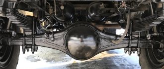
They were used on all LiAZ buses, on some LAZ buses, on trolleybuses from the Engels ZIU plant, and on all Ikarus buses. Therefore, enterprises associated with bus transportation had no shortage of them. The bridges were reliable and the LiAZ models were used to cross the bus itself. I decided to calculate what speed range the MAZ-500 truck would have in all gears with a rear axle with a gear ratio of 8.21 (the main gearbox is 2.666, and the final drive is 3.11) and on ID-304 tires, with a statistical radius of 0.526 m. The result is a table with maximum speed equal to 76.71 km/h.
After talking with the drivers, I learned that MAZs are mainly equipped with axles from LiAZ and LAZ. The first bridge had wheels fastened with wedges, and the second with footings.
Not available:
| № | Part code | Name | Part Information |
| 500-2402020 | Spiral gears driving and driven | Quantity per 5335 2) 5549 3) 5429 4) 509A 5) 504B 1 Model 500 Group Rear axle Subgroup Rear axle gearbox (main gear) Part serial number 020 | Not available |
| 500-2402021-B1 | Spiral drive gear with bearing and bearing housing assembly | Quantity per 5335 2) 5549 3) 5429 4) 509A 5) 504B 1 Model 500 Group Rear axle Subgroup Rear axle gearbox (main gear) Part serial number 021 Additionally Interchangeable with a part previously released under the same number | Not available |
| 500A-2402050 | Drive gear bearing housing cover assembly | Quantity per 5335 2) 5549 3) 5429 4) 509A 5) 504B 1 Model 500A Group Rear axle Subgroup Rear axle gearbox (main gear) Part serial number 050 | Not available |
| 500A-2402059 | Oil seal spring | Quantity per 5335 2) 5549 3) 5429 4) 509A 5) 504B 1 Model 500A Group Rear axle Subgroup Rear axle gearbox (main gear) Part serial number 059 | Not available |
| 500-2402044 | Retaining ring | Quantity per 5335 2) 5549 3) 5429 4) 509A 5) 504B 1 Model 500 Group Rear axle Subgroup Rear axle gearbox (main gear) Part serial number 044 | Not available |
| 102308-K1 | Rear drive gear bearing assembly | Quantity per 5335 2) 5549 3) 5429 4) 509A 5) 504B 1 Finish: black | Not available |
| 500-2402017 | Spiral gear | Quantity per 5335 2) 5549 3) 5429 4) 509A 5) 504B 1 Model 500 Group Rear axle Subgroup Rear axle gearbox (main gear) Part serial number 017 | Not available |
| 500-2402029-A | Bearing spacer ring | Quantity per 5335 2) 5549 3) 5429 4) 509A 5) 504B 1 Model 500 Group Rear axle Subgroup Rear axle gearbox (main gear) Part serial number 029 Additionally Interchangeable with a part previously released under the same number | Not available |
| 500-2402076-A | Bearing adjusting washer | Quantity per 5335 2) 5549 3) 5429 4) 509A 5) 504B 1 Model 500 Group Rear axle Subgroup Rear axle gearbox (main gear) Part serial number 076 Additionally Interchangeable with a part released earlier under the same number | Not available |
| 500-2402078-A | Bearing adjusting washer | Quantity per 5335 2) 5549 3) 5429 4) 509A 5) 504B 1 Model 500 Group Rear axle Subgroup Rear axle gearbox (main gear) Part serial number 078 Additionally Interchangeable with a part previously released under the same number | Not available |
| 500-2402077-A | Bearing adjusting washer | Quantity per 5335 2) 5549 3) 5429 4) 509A 5) 504B 1 Model 500 Group Rear axle Subgroup Rear axle gearbox (main gear) Part serial number 077 Additionally Interchangeable with a part previously released under the same number | Not available |
| 500A-2402049 | Drive gear bearing housing | Quantity per 5335 2) 5549 3) 5429 4) 509A 5) 504B 1 Model 500A Group Rear axle Subgroup Rear axle gearbox (main gear) Part number 049 | Not available |
| 500A-2402063 | Drive gear flange | Quantity per 5335 2) 5549 3) 5429 4) 509A 5) 504B 1 Model 500A Group Rear axle Subgroup Rear axle gearbox (main gear) Part serial number 063 | Not available |
| 500A-3507075 | Oil catcher | Quantity per 5335 2) 5549 3) 5429 4) 509A 5) 504B 1 Model 500A Group Brakes Subgroup Parking brake Part number 075 | Not available |
| 500-3507077 | Pad | Quantity per 5335 2) 5549 3) 5429 4) 509A 5) 504B 1 Model 500 Group Brakes Subgroup Parking brake Part number 077 | Not available |
| 500A-2402052 | Drive gear oil seal assembly | Quantity per 5335 2) 5549 3) 5429 4) 509A 5) 504B 1 Model 500A Group Rear axle Subgroup Rear axle gearbox (main gear) Part serial number 052 | Not available |
| 500A-2402051 | Bearing housing cover | Quantity per 5335 2) 5549 3) 5429 4) 509A 5) 504B 1 Model 500A Group Rear axle Subgroup Rear axle gearbox (main gear) Part number 051 | Not available |
| 500-2402084-11 | Bearing housing cover gasket | Quantity per 5335 2) 5549 3) 5429 4) 509A 5) 504B 1 Model 500 Group Rear axle Subgroup Rear axle gearbox (main gear) Part serial number 084 Additionally Not interchangeable with a part previously released under the same number | Not available |
| 500-2402075 | Drive gear oil deflector | Quantity per 5335 2) 5549 3) 5429 4) 509A 5) 504B 1 Model 500 Group Rear axle Subgroup Rear axle gearbox (main gear) Part serial number 075 | Not available |
| 376322-P | Washer | Quantity per 5335 2) 5549 3) 5429 4) 509A 5) 504B 1 Coated uncoated | Not available |
| 311701-P29 | screw | Quantity per 5335 2) 5549 3) 5429 4) 509A 5) 504B 1 Galvanizing and passivation coating (zinc with chromating) | Not available |
| 258086-P29 | Cotter pin | Quantity per 5335 2) 5549 3) 5429 4) 509A 5) 504B 1 Galvanizing and passivation coating (zinc with chromating) | Not available |
| 250510-P29 | screw | Quantity per 5335 2) 5549 3) 5429 4) 509A 5) 504B 2 Galvanizing and passivation coating (zinc with chromating) | Not available |
| 400590-P2 | Ring | Quantity per 5335 2) 5549 3) 5429 4) 509A 5) 504B 1 Coating phosphating and oiling | Not available |
| 500-2402064 | Ring sealing | Quantity per 5335 2) 5549 3) 5429 4) 509A 5) 504B 1 Model 500 Group Rear axle Subgroup Rear axle gearbox (main gear) Part number 064 | Not available |
Finding the Raba-MAN rear axle and preparing for its installation
I began to slowly look for a bridge from LiAZ and after a while, the opportunity arose to purchase one from a decommissioned bus.
The only condition for obtaining it was to independently remove the bridge from the body. It was necessary to hire a truck crane and cut out the rear and front axles, because... the bus was converted into a cold storage facility. He cut off his bridge and loaded it into the car.
I brought the bridge to the garage and immediately began inspecting it. I looked under the pad shields and made sure that the pads were thick enough. Next, I proceeded to remove the gearbox flange.
Also, I found another rear gearbox flange from a MAZ-500 and gave both flanges to turners so that they could fit the cardan flange to the bus axle flange. I tightened the new flange with studs and nuts and additionally welded it with electric welding.
The LiAZ bridge is much thicker in thickness, in the area where the springs are attached, than the MAZ bridge, and therefore we had to grind out new elongated stepladders with extra threads and bend them in the forge.
On the bottom of the bridge, I made platforms from 20 mm plates and drilled them on a drilling machine. I also made new upper bridge pads for the springs and drilled them for the nuts of the spring tie bolts.
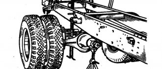
Replacing the MAZ-500 rear axle with the LiAZ-677 rear axle
Having done all this, I finally started replacing the rear axle and to do this, I hung up the rear of the car.
He unscrewed the stepladders and removed them. I unscrewed the driveshaft from the axle and the brake hoses from the brake chambers. Then, I raised the rear of the car so that the springs barely touched the MAZ axle and measured the distance from the center of the shank to the ground. After that, I raised the rear of the car even higher and rolled the rear axle assembly with wheels completely out from under the car. I removed the rear wheels from the MAZ bridge and began installing them on the bus bridge, using wedges and nuts along with the intermediate ring from the bus.
When the wheels were installed, I immediately noticed the reduced distance between the tires and I didn’t like it.
Next, I rolled the new bridge under the car and lowered the rear part of the frame onto it so that the spring pads would fit between the bridge and the springs. Then, I turned the bridge in such a way that the distance from the ground to the shank became 3 cm greater than it was with the MAZ bridge.
After that, I began to assemble stepladders, pads from the bottom of the bridge and attach nuts. Also, it was necessary to trim the fastenings on the bridge that included the bus stepladders. After some light tightening, I began welding the upper platforms of the bridge under the springs. Next, I tightened the stepladders, put the driveshaft in place and connected the brake chambers.
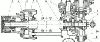
3.6.5 Main gears and differentials of MAZ vehicles
3.6.5 Main gears and differentials of MAZ vehicles
On MAZ-64227 vehicles, two drive axles are installed - a middle one with a through shaft and a rear one, and on MAZ-54322 - only a rear axle. The beam, cross-axle differential and wheel drive of the middle axle are maximally unified with similar units of the rear axle. The beam of variable cross-section is made of two stamped halves welded together.
The main gear of the rear axle consists of a central bevel gearbox and planetary wheel gears located in the wheel hubs.
The central gearbox (Figure 3.48) is single-stage, consists of a pair of bevel gears with circular teeth and a cross-axle differential. The gearbox parts are mounted in the crankcase 15. The gearbox is installed in the window of the rear axle beam and is centered in it with a special collar and alignment pins.
The drive bevel gear 5, made as one piece with the shaft, is installed in two tapered roller bearings - the larger rear one 4 and the smaller front one 7. The outer rings of the tapered roller bearings are located in the bearing housing 15 and are pressed all the way into the crankcase shoulders. A spacer ring and shims 6 are installed between the inner rings of the tapered roller bearings. The required preload in the tapered roller bearings is determined by selecting the thickness of the shims. A flange 9 of the propeller shaft is installed on the splined part of the drive gear shaft. All parts located on the drive gear shaft are tightened with a castle nut 10.
The driven bevel gear is bolted to cups 2 and 23 of the differential. The engagement of the bevel gears of the central gearbox is regulated by changing a set of shims 16 of various thicknesses installed between the bearing housing and the gearbox housing. During factory assembly, a bevel gear pair is pre-selected (mating) based on contact and noise. Therefore, if it is necessary to replace one gear, the other must also be replaced.
1, 19 – axle shafts; 2, 23 – differential cups; 3 – driven gear; 4, 7, 22 – bearings; 5 – drive gear; 6, 16 – adjusting shims; 8 – oil seal; 9 – flange; 10 – nut; 11 – washer; 12 – sealing ring; 13 – cover; 14 – bolt; 15 – bearing housing; 17 – satellite; 18 – thrust ring; 20 – differential bearing nut; 21 – bearing cover; 24 – cross; 25 – semi-axial gear; 26 – washer; 27 – bearing nut stopper; 28 – axle housing
Figure 3.48 – Main gear and differential of the rear drive axle of a MAZ vehicle
The rear axle differential is bevel, has four satellites 17 and two semi-axial gears 25, which are bevel spur gears. The satellites are put on; the spikes of the crosspiece, resting on them through bushings made of bronze tape. Steel thrust rings are installed between the satellites and the bases of the crosspiece tenons. The support for the satellites in the cup is a stamped bronze washer of spherical shape. The crosspiece with four tenons fits into the cylindrical holes formed in the parting plane of the differential cups when they are processed together. If replacement is necessary, the differential cups must be replaced as a set. In the cylindrical bores of the differential cup hubs, axle gears are installed, the inner surfaces of the hubs are made in the form of holes with involute splines for connection with the axle shafts. Bronze floating washers are installed between the supporting surfaces of the ends of the semi-axial gears and the differential cups. Tapered roller bearings 22 are installed on the hubs of the differential cups, with the help of which the differential rests on the holes in the gearbox housing, formed by bosses in the crankcase and two detachable covers 21, which are centered in it using bushings and secured with bolts.
Adjustment of the preload of the tapered roller bearings of the differential is carried out by nuts 20, which are fixed in the desired position by the protruding mustache of the stopper 27.
The parts of the central gearbox are lubricated by oil sprayed by the ring gear of the driven bevel gear. An oil pocket is cast in the gearbox housing, into which the oil sprayed by the driven bevel gear is thrown away, and the oil drained from the walls of the gearbox housing settles. From the oil pocket, oil is supplied through a channel to the bearing housing and enters the area between the bearings. Thanks to the pumping action of the tapered rollers, they are lubricated, pumping oil in opposite directions: the rear bearing returns the oil to the crankcase, and the front bearing towards the driveshaft flange.
A rubber O-ring is installed between the flange and the bearing. On the flange side, the bearing housing is closed with a cast cover, into which two reinforced self-clamping rubber seals are pressed. The working edges of the seals are pressed against the flange surface, sealing it.
To improve the lubrication of the differential parts, holes are made to the right cup into which stamped scoops are inserted and welded, capturing the lubricant from the gearbox housing and directing it to the differential parts located in the cups. The oil filler neck is welded to the rear cover of the axle beam and is closed with a plug.
The fully assembled center gearbox is installed in the large front hole of the axle beam and secured with studs and nuts to its vertical mounting surface, which is sealed with a gasket.
The wheel drive (Figure 3.49) is a planetary gearbox consisting of spur gears with external and internal gearing. From the drive gear of the wheel drive, rotation is transmitted to four satellites 14, evenly spaced in a circle around the drive gear.
The satellites rotate on axles 10, fixed in the holes of the movable carrier 12, connected by bolts to the hub of the drive wheels, in the direction opposite to the direction of rotation of the drive gear. Rotating on their axes, the satellites roll along the teeth of the internal gearing of the driven gear 15, which is fixedly fixed by means of a hub 16 on the splined end of the axle beam axle.
The drive gear has a hole with involute splines that mate with the splines of the outer end of the axle shaft. The axial movement of the drive gear on the axle shaft is limited by a spring retaining ring. The axial movement of the axle shaft is limited by the block 7 and the axle shaft stop 8. The satellites with needle bearings are mounted on the axle, placed in the coaxial holes of the carrier 12 and secured in it against axial movement by spring retaining rings. The satellite axle is equipped with washers to prevent the gears and bearings of the satellite axles from touching the carrier.
The driven gear 15 of the wheel transmission rests with its internal gear ring on the external gear ring of the driven gear hub 16, and the splined end of this hub is mounted on the splined part of the axle beam axle. This connection does not allow rotation of the driven gear, but its axial movement is limited by a spring ring that fits into the groove of the driven gear ring gear and rests against the inner end of the hub gear ring 16.
1 – washer; 2, 33 – nuts; 3.5 – plugs; 4 – drive gear; 6 – axle shaft; 7 – cracker; 8 – axle stop; 9 – cover; 10 – satellite axis; 11 – needle bearing; 12 – carrier; 13, 32 – sealing rings; 14 – satellite; 15 – driven gear; 16 – driven gear hub; 17 – hub; 18 – bearing; 19, 20 – bolt; 21 – brake shield; 22 – axis; 23 – spring; 24 – expansion fist; 15 – oil catcher; 26 – oil seal; 27 – oil seal cover; 28 – brake pad; 29 – brake drum; 30 – bolt; 31 – bearing
Figure 3.49 – Wheel drive of the drive axle of a MAZ vehicle
The satellite axle is equipped with washers to prevent the gears and bearings of the satellite axles from touching the carrier. The carrier is closed from the outside with a cover 9 and, in conjunction with the wheel hub, is sealed with a rubber ring 13.
Lubrication of gears and bearings of the wheel drive is carried out by sprayed oil, which is poured through the hole in the cover 9, closed with plug 5. The lower edge of this hole determines the required oil level in the wheel drive. The drain hole, closed by plug 3, is made in the wheel hub, since the cavities of the wheel drive and the wheel hub communicate.
When the car moves, the oil in the wheel drive cavity and wheel hubs is mixed and supplied to the gear bearings, wheel hubs and gears. To improve the supply of lubricant to the bearings of the satellite axles, the axles are made hollow and have radial holes in them for supplying oil to the bearings.
The main gear of the MAZ-64227 middle drive axle consists of a central gearbox and planetary wheel gears located in the wheel hubs.
The central gearbox (Figure 3.50) is two-stage, consists of a pair of spur gears 10, 25, a center differential 29, a pair of bevel gears 3, 42 with circular teeth and a cross-axle differential 43. The gearbox parts are mounted in the crankcases 7, 8, 51. On the splines of the front end The axle drive shaft 30 has a flange 17 installed, which is sealed with a rubber-reinforced oil seal 16 mounted in the cover 15.
The axle drive shaft 30 has a front support in a ball bearing 14, placed in a cup installed in the hole in the crankcase 7. The rear end of the shaft 30 rests on a cylindrical roller bearing installed in the hub bore of the center differential semi-axial bevel gear 29, which, in turn, rests onto a cylindrical roller bearing 31 mounted in the crankcase bore 51.
The splined part of the differential side gear hub is mated to the front splined end of the rear axle drive shaft 32. On the back of the hub of the drive cylindrical gear 25 there is a gear ring of the second semi-axial bevel gear, and in front there is a gear ring for mating with the center differential locking clutch 19, which is mounted on the splined middle part of the axle drive shaft 30. The drive cylindrical gear rests on two tapered roller bearings 13. The outer rings of these bearings are secured against axial movement by thrust rings 23 and locking rings 24, and adjusting washers 21 are installed between the inner rings.
1, 12 – satellites; 2, 46 – support washers; 3 – driving bevel gear; 4, 27 – spacers; 5 – adjusting shims; 6, 21, 41 – adjusting washers; 7 – crankcases; 8 – bearing housing; 9, 13, 14, 31, 35, 47 – bearings; 10 – driven cylindrical gear; 11, 18, 40 – nuts; 15, 37 – covers, 16, 38 – oil seals; 17, 39 – flanges; 19 – center differential locking clutch; 20 – center differential locking mechanism; 22 – clutch engagement fork; 23 – thrust washer; 24 – lock washer; 25 – driving cylindrical gear; 26 – center differential lock activation sensor; 28, 44 – crosses; 29 – center differential; 30 – axle drive shaft; 32 – output shaft; 33 – axle shaft; 34 – glass; 36 – bolt; 42 – driven gear; 43 – cross-wheel differential; 45 – semi-axial gear; 48 – cover; 49 – differential bearing nut; 50 – stopper; 51 – gear housing
Figure 3.50 – Central gearbox of the middle axle of a MAZ vehicle
The crosspiece of the center differential has a spline hole, with which it is put on the rear splined part of the shaft 30. The four spikes of the crosspiece on the bushings are equipped with satellites, which are bevel spur gears. The support for the satellites in the cup is a stamped bronze washer of spherical shape. The crosspiece with four tenons enters the cylindrical holes formed in the cavity of the cup connector when they are processed together. Centering of the cups is achieved by having a collar on one of them, and a corresponding groove and pins on the other. The differential cups are connected to each other with bolts. If replacement is necessary, the differential cups must be replaced as a set. The differential crosspiece is secured against axial movement at the front by a spacer sleeve 27, and at the rear with a thrust washer and a nut locked with a locking pin.
The center differential is locked by moving the locking clutch 19 back until its teeth engage with the internal teeth of gear 25. The center differential lock drive is electro-pneumatic. The center differential locking clutch is controlled by the center differential locking mechanism 20, which is mounted on the upper hatch of the crankcase 7 as a result of the movement of the rod with the fork 22 mounted on it, engaging the clutch when air is supplied to the above-piston space of the locking mechanism. When the rod moves to the rearmost position, the control light on the instrument panel lights up as a result of the contacts of sensor 26 closing the differential lock.
The rear axle drive shaft 32 in the front part through the center differential gear 31 rests on a cylindrical roller bearing, and in the rear part on two tapered roller bearings 35. Adjusting washers 41 are installed between the inner rings of these bearings. The propeller shaft flange 39 is sealed with a rubber-reinforced oil seal mounted in a cast cover 37.
The driving bevel gear 3 is made and mounted in two tapered roller bearings in the bearing housing 8 similarly to the driving bevel gear of the rear axle. At the spline end of the drive bevel gear 3, a driven cylindrical gear 10 is installed, secured with a castle nut 11 and transmitting torque to the drive bevel gear of the middle bridge from the axle drive shaft 30.
The cross-axle differential of the middle axle is maximally unified with the cross-axle differential of the rear axle.
The driven bevel gear 42 is located to the right (along the direction of the vehicle) of the drive bevel gear, and not to the left, as in the central gearbox of the rear axle. Its fastening to the differential cups is also bolted. The wheel drive of the middle axle is similar to the wheel drive of the rear axle.
Speed range of MAZ-500 with a new rear axle
After driving like this for some time, I came to the conclusion that the increase in speed was almost unnoticeable.
Of course, there is less noise from the bridge, and the brakes have become more effective, because The area of the Raba-MAN brake pads is larger than that of the MAZ-500 axle. However, I didn't like the wheel mount at all. To replace the bolt under the wedges, it was necessary to remove the crown. Who came up with such an impractical design remains a mystery to me. But I liked the fastening of the crown itself, because... The crown was fastened not only through the engraver washers and nuts, but also conical crackers were installed under the washers.
By the way, the crowns on the Super MAZ are attached without cone crackers and therefore can often be seen in scrap metal.
After installing the new axle, the short tire spacing was also a concern. With a standard load and 320 tires, a black stripe constantly appeared between the wheels, which indicated that the tires were touching while driving.
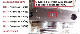
The gear ratio of the new axle was 7.61 (gearbox 2.08, final drive 3.66). I calculated the speed table and realized that the changes were minimal.
The car's speed range has not changed significantly, and the maximum speed has increased by only 7 km/h and reached 83.57 km/h.
Installation of a gearbox with a gear ratio of 1.79 and crowns from a trolleybus
To further increase the speed of my truck, I decided to consult with the aggregators at the main bus depot.
I contacted specialists, and when they heard that I needed a faster gearbox for MAZ, they immediately said that I needed to look for a gearbox with a gear ratio of 1.79 (installed on the city Ikarus and LAZ with engines from ZIL or Ural) and it would be advisable to find one for it more crowns from the trolleybus. Then you can safely ride on 320 tires, because in a trolleybus and a MAZ the intermediate ring is the same thickness.
I found a 1.79 high-speed gearbox and went to the trolleybus depot to look for trolleybus crowns. I didn’t have to search for long, and the crowns assembled with wedges, nuts and bolts were soon in my possession.
Returning home, I immediately began replacing the gearbox and crowns. Replacing the gearbox is quite easy, it is not heavy. The only difficulty is getting him off the bridge and there is one trick here.
The gearbox must be turned 90 degrees (the planetary gear must be parallel to the bridge), then the planetary gear will fit into the cutouts of the bridge and the gearbox will be removed. To install a new gearbox in the bridge, you need to do this operation in reverse order.
Replacing the crowns was also no problem. True, the trolleybus bridge has some kind of crutches, but they are inserted easier than those that I have seen on other cars.
Flatbed with gear ratio 3.66, trolleybus crown and wheel clamps
The total gear ratio of the new axle was 6.55 (gearbox 1.79, final drive 3.66), and the gear ratio of the MAZ axle was 8.21.
Thus, the speed of the car increased by 25% (8.21/6.55=1.25), and the thrust decreased by the same 25%.
After replacing the central gearbox, the speed range increased, and the maximum speed became 97.09 km/h.
A car with 20 tons became easy to walk on asphalt at a speed of 80 km/h, and the best way to start when loaded was in 1st gear. With 25 tons of cargo on very steep climbs, it was necessary to engage 1st gear and it felt like the car was going to the limit of its strength. Thus, if the load were over 25 tons, then it would be very difficult to cross the Urals by car.
I drove on this rear bridge for about 2 years and traveled from the Urals to Altai and Taman. On asphalt, I easily left behind KamAZ road trains with 210 hp engines.
Technical characteristics of MAZ vehicles
Basic adjustment data of MAZ
| Gap between the toe of the rocker arm and the end of the engine valve (cold), mm | 0,25—0,30 |
| Free play of the clutch pedal, mm. | 34—43 |
| Gap between the rear cover of the clutch booster valve housing and the adjusting nut, mm | 3,5+0,2 |
| Free travel of brake pedal, mm | 14—22 |
| Brake chamber rod stroke, mm | 25—35 |
| Free play of the steering wheel with the hydraulic booster operating in a position corresponding to the vehicle moving in a straight line, degrees | 10—15 |
| Front wheel toe-in, mm | 3-5 |
| Handbrake handle stroke, mm | 110—160 |
| Permissible axial runout of wheels, mm | 8 |
| Permissible belt deflection, mm: | |
| compressor | 5—8 |
| with a force of 3 kg, | |
| water pump | 10—15 |
| at a force of 3 kg | |
| power steering pump | 10—15 |
| at a force of 4 kg | |
| generator | 10—12 |
| at a force of 4 kg |
Main technical characteristics of MAZ
| MAZ-500A | MAZ-504A | MAZ-516 | |
| Load capacity on paved roads, kg | 8 000 | 14 500 | |
| Weight of a towed trailer or semi-trailer with cargo on paved roads, kg | 12000 | 17 750 | |
| Total weight of the vehicle with cargo, kg | 14825 | 14 375 | 23 525 |
| Total weight of the road train with cargo, kg | 26 825 | 24375 |
| Distribution of vehicle weight without load, kg: | |||
| to the front axle | 3 350 | 3 650 | — |
| » rear axle | 3 250 | 2 750 | |
| Weight distribution of the vehicle with cargo, kg: | |||
| to the front axle | 4 825 | 4 375 | 5 525 |
| » rear axle | 10 000 | 10 000 | 10 000 |
| » additional axle | — | — | 8 000 |
| Vehicle base, mm | 3 950 | 3 400 | 3 850 + 1 455 |
| Rear wheel track (between the centers of double slopes), mm | 1 900 | 1 900 | 1 900 |
| Front wheel track, mm | 1 950 | 1 950 | 1 950 |
| Ground clearance, mm: | |||
| to the front axle | 290 | 290 | 290 |
| » rear axle housing | 290 | 290 | — 290 |
| Minimum turning radius in both directions, m: | |||
| by buffer | 9,5 | 8,5 | 1,2 |
| » front outer wheel track | 8,5 | 7,5 | 11 |
| Overhang angles (with load), degrees: | |||
| front | 28 | 28 | 28 |
| rear | 26 | 48 | 28 |
| Overall dimensions, mm: | |||
| length | 7 140 | 5 630 | 8 520 |
| width | 2 600 | 2 600 | 2 600 |
| height | 2 650 | 2 650 | 2 650 |
| Platform dimensions mm: | |||
| length | 4 860 | — | 6 200 |
| width | 2 480 | — | 2 340 |
| height | 670 | — | 655 |
| Body capacity (without additional revolutions), m3 | 8,05 | — | 9,5 |
| Highest speed at full load on a horizontal section of a straight road, km/h | 85 | 85 | 85 |
| Braking distance of a vehicle with a full load without a trailer, moving at a speed of 40 km/h on a horizontal section of a dry road with a hard surface, m, no more | 18 | 21 | 20 |
| Control fuel consumption per 100 km, l | 22 | 32 | 30 |
Technical characteristics of the MAZ engine
| Model | YaMZ-236 |
| Type | four-stroke compression ignition |
| Number of cylinders | 6 |
| Cylinder arrangement | V-shaped with camber angle 90° |
| Cylinder operating order | 1 4 2 5 3 6 |
| Cylinder diameter, mm | 130 |
| Piston stroke, mm | 140 |
| Working volume of all cylinders, l | 11,15 |
| Compression ratio | 16,5 |
Noise in the rear axle and problems with planetary gear bearings
During the work, malfunctions appeared that made me think.
The rear axle was noisy, but opening the side axles revealed nothing, only not a single axle shaft was pulled out. After much consultation and reflection, I came to the conclusion that the reason was in the gearbox. When all the pullers for removing the axle shafts were broken, and the axle shaft still wouldn’t budge, we had to proceed with surgery. On the rear side of the gearbox, opposite the axle shaft exiting it, a hole with a diameter of 15 mm was cut by electric welding and the axle shaft was cut through it with an electrode. More than a third of the electrode was not burned.
Next, I turned the gearbox, pulled it out of the bridge and understood the cause of the malfunction. The bearings on the planetary gear flew off and one axle shaft was welded to the differential side gear.
The gearbox housing has one-piece yokes and removing the yokes from the differential box is not such an easy job. After struggling for some time, I finally managed to complete the task.
Until you remove the inner races of the bearing, you will not be able to remove the planetary gear with the differential. The gearbox is compact, but requires specific tools for repair. The most interesting thing was that the gears had intact teeth.
Using an old LAZ gearbox as spare parts, I restored the 1.79 gearbox, but was afraid to install it. I found another one just like it and an axle shaft for it, and then installed it all on the car. This bridge repair was the last, because... in the future, he didn’t give me any more surprises.