Starter UAZ 469: device and repair
The UAZ 469 car starter performs a very important mission. It takes on the charging current from the battery and starts the car engine. Before the appearance of the starter, the engine was started with a special steel handle. Through the radiator grille, it was inserted with two hooks into a ratchet connected to the crankshaft. By turning the handle clockwise, the driver spun the crankshaft. At this moment, the carburetor sucked in gasoline, the ignition coil supplied a spark to the spark plugs, and the engine started.
Electrical wiring components for UAZ 469, UAZ 390945 and other models
The electrical circuit of the UAZ 3151 4 includes 69 positions; it is possible to additionally connect special fog lights, but the installation of a switch type 343.01.03 is required. It will be mounted directly on the dashboard in a convenient location. The general wiring diagram of a machine includes an extensive list of different devices.
This is a front light, headlights that are easy to replace if necessary. An audio signal is also connected to the general system. Further, the UAZ wiring diagram includes a special fuse and additional resistance. The circuit has a connection to the side direction indicators, and a switch for the heater is located right there.
The wiring supplies the generator, there are connection points for the light that illuminates the engine compartment, and outputs for the heater fan motor. Modern UAZ electrical wiring includes spark plugs powered by it. A relay is installed for indicators; it is used to ensure the operation of emergency and turn signals.
The electrical circuit has outputs to a coil, a starter relay, there is a special sensor-distributor, and a switch. In one area there are the following points: turn off the masses, hazard warning lights, battery, electric washer. There is a separate connection for the fuse box and the following sensors:
- emergency pressure for oil;
- fuel readings;
- for oil pressure indicator;
- overheating of used coolers;
- temperatures of the coolers used;
- determining the brake fluid level.
1.Low voltage ignition coil; 2.Transistor electronic switch; 3. Sensor-distributor (distributor); 4.Electric spark plugs; 5.Fuse block; 6.Emergency breaker; 7.Additional electrical resistance.
The electrical diagram includes connection points for the starter, speedometer, windshield wiper and relay for it, EPH unit, voltmeter. There are the following components:
- relay for car headlights;
- sockets used to power portable lamps;
- parking brake switches, braking systems.
For electrical equipment of UAZ 31512(14) or UAZ 390945, the following switches are installed:
- for brake signal;
- for parking brake;
- alarm;
- interior light lamps;
- sound signal;
- rear fog lamp;
- ignition;
- reverse lights.
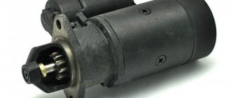
Starter UAZ 469
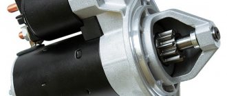
Power units for Russian UAZ 469 vehicles are produced by two enterprises. These are the Ulyanovsk and Zavolzhsky motor plants. The completion of engines with starters in both companies is carried out by Pramo-Electro LLC, Rzhev, Tver Region. From here, engine builders receive a UAZ 469 starter under the factory catalog number 42.3708.
The starter of the UAZ-469 car is an electric motor that consumes direct current. It contains a series excitation winding. An electromagnetic traction relay and a drive with a freewheel are installed. It is installed on the left side of the engine.
Now the Rzhev plant has mastered the production of a more modern device. The improved automobile starter received a new catalog number 4211.3708-01. The driver turns on the starter remotely using the ignition switch. By turning the key in the ignition, it closes the DC circuit.
Electrical energy from the battery begins to flow to its primary winding, exciting it. At the same time, the retractor relay pushes the working gear. It engages with the toothed flywheel of the engine, performing a rotational movement. The flywheel spins up, all the working parts begin to move, and the power unit starts up.
Main starter relay
ATTENTION! A completely simple way to reduce fuel consumption has been found! Don't believe me? An auto mechanic with 15 years of experience also didn’t believe it until he tried it. And now he saves 35,000 rubles a year on gasoline! Read more"
The car's electric starting system includes, in addition to the starter and relay, also starter on/off elements, various connecting wires, the main power source (battery), etc.
The starter relay or VR is activated after turning the key in the ignition switch. The BP armature and the freewheel lever move, and the bendix engages with the flywheel crown. This ensures normal engine starting.
To be able to adjust the system, you need to disconnect the current wiring from the VR. The control terminal is marked on the terminal with the letter M.
Then the battery is removed from its original place and connected to the M and S terminals marked on the terminals. Thus, the purpose of the operation performed is to shift the bendix. And in order to connect the BP to the starter, you must first adjust the gap between the bendix and the stop. It is also recommended to adjust the gasket located between the drive and the BP.
Device
The UAZ 469 starter, number 42.3708, consists of the following elements:
- drive side cover;
- driving ring;
- thrust ring;
- lock ring;
- drive unit;
- anchor;
- frame;
- brush;
- traverse;
- thrust washer;
- adjusting washer;
- lock washer;
- manifold side cover;
- contact bolt;
- contact plate;
- relay cover;
- return spring;
- stock;
- relay armature;
- compensating spring;
- buffer spring;
- gear;
- screw M5x14;
- tie rod nut;
- screw M6x16;
- M8 nut;
- relay coil input;
- screw M6x30;
- lever arm;
- M8 nut;
- lever axis.
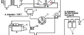
Starter connection diagram
Connection diagram of the UAZ 469 42.3708 starter in the vehicle’s on-board circuit:
- ground switch;
- rechargeable battery;
- additional starter relay;
- ignition switch (lock);
- voltmeter;
- contact disk;
- pull-in winding;
- holding winding;
- UAZ 469 starter traction relay;
- UAZ 469 starter.
Specifications
The direction of rotation is right.
Rated voltage 12 V.
Power when powered by a 60 Ah battery 1.2 kW 1.65 hp
Idling at 20 °C:
- current consumption, no more than 75 A.
- voltage at the starter terminals, no more than 12 V.
- Rotor speed, not less than 5000 min -1.
Full braking at 20°C:
- braking torque, 1.6±0.16 kgf•m
- current consumption, no more than 520 A.
- voltage at the starter terminals, no more than 7 V.
conclusions
The UAZ 469 has proven itself to be a fairly reliable off-road vehicle for multi-purpose use. The civilian population actively uses it for their own purposes also due to the fact that it can be serviced with its own hands, using factory documentation and advice from craftsmen.
The electrical equipment of UAZ-31512, UAZ-31514 and UAZ-31519 vehicles is made according to a single-wire circuit. The negative terminals of the sources and consumers of electricity are connected to the body and other components of the car, which act as a second wire. On-board DC network, with a nominal voltage of 12 Volts. Protection of electrical circuits is organized through a fuse box.
To switch the main circuits of the car, a combined ignition switch is used, consisting of a contact part and a mechanical anti-theft device with a lock. When the engine is not running, all consumers are powered by the battery, and after the engine is started - by alternating current with a built-in rectifier unit. When the generator is running, the battery is charged.
When the engine is idling, the generator rotor speed and, accordingly, the supplied current are insufficient to provide power to powerful consumers, such as headlights, windshield wipers, electric fans, and alarms. In this mode, the battery will be discharged.
Location and purpose of fuses for electrical circuits of the on-board network of UAZ-31512, UAZ-31514 and UAZ-31519.
To protect the vehicle's external lighting electrical circuits from overload, a bimetallic fuse 29.3722 or similar is used, which is installed under the instrument panel on the left. Three 10 Amp fuses are installed in the PR103 fuse box, mounted on the partition of the engine compartment. They protect:
No. 1 – circuits of control devices; No. 2 – direction indicator circuits; No. 3 – alarm and sound signal circuits.
Fuse No. 1 is located closer to the right side of the vehicle. The heater fan motor power circuit is protected by a fuse with a rated current of 6 Amps. The fuse is located on the wiring harness next to the heater switch. UAZ-31512, UAZ-31514 and UAZ-31519 vehicles can be equipped with other additional fuses, depending on the configuration.
Checking the electrical circuits of the on-board network of UAZ-31512, UAZ-31514 and UAZ-31519 under voltage.
Live circuits are also checked with an ammeter. The voltmeter is connected in parallel to the device or circuit section being tested. Measurement range 0–15 or 0–25 Volts DC. The negative wire (probe) is connected to ground, the positive wire is connected to consumers or current sources. By the voltage drop, you can determine a malfunction of the supply circuit - a break, oxidation of contacts, etc., as well as a short circuit in the consumer.
To check live circuits, you can also use a test lamp with a power of no more than 3–4 W, designed for a voltage of 12 Volts, for example the AMH12-3 lamp used in the instrument panel.
The ammeter must have an upper measurement limit of at least 10 Amps DC, as well as overload protection. We connect the ammeter in series with the device being tested. The plus of the device is connected to the current source, and the minus is connected to the consumer’s plus. If the current is less than required, then the electrical circuit is faulty, and if it is more, a short circuit has occurred in the consumer.
UAZ starter device
The UAZ starter has a torque of no more than 1.6 kgf/m, and a rated power of 1.7 kW. The armature shaft has a clutch and a drive gear. The first element transmits torque in one direction - from the device in question to the motor.
UAZ 469 starter maintenance
UAZ 469 starter maintenance:
1. Periodically check the condition of the clamps on the contacts in order to prevent them from loosening, dust, dirt, corrosion, and oxidation.
2. Inspect the collector, remove the protection casing. Eliminate identified defects, clean contacts, lubricate with Litol lubricant.
3. Open cover 13 and check all elements. Clean the contacts and blow with compressed air.
4. Tighten the UAZ 469 starter mounting bolts.
5. When operating a vehicle in a forest, quarry, or rural area, it is necessary to periodically dismantle the UAZ 469 starter and clean it with a wire brush to remove dust, dirt, and deposits.
10000 km
Check the UAZ 469 starter, perform maintenance-1 with the following routine operations:
2.If necessary, tighten loose connections.
3. It must be remembered that a violation of the tightness of the wire from the battery to the starter leads to an increase in the transition resistance in its circuit.
4. As a result, this reduces power and impairs starting.
30000 km
Check the UAZ 469 starter, perform maintenance-2 with the following operations:
1.Remove the protection tape.
2.Blow out the collector with compressed air.
3.Check the brushes and commutator.
Once every year, but at least every 25,000-30,000 km of the vehicle, it is necessary to remove the UAZ 469 starter. It should be disassembled, thoroughly wiped and the parts blown with compressed air. If defective parts, assemblies, or mechanisms are identified, replace them with new ones or repair them. Assemble, adjust, perform control check.
Additional VR starter
On modern cars, an additional VR starter is a priori provided. On older cars, the relay is installed and connected independently.
The advantages of installing an additional VR are obvious:
- Protects the starter device from burnout of contacts in the lock, which occurs for various reasons (long start-up, banal wear, etc.);
- It has a positive effect on the loading of contacts of the same ignition switch, as a result of which the contacts remain operational longer;
- Protection of the starter from a situation where, due to a “glitch” of the key in the ignition switch (the engine has started, but the starter continues to spin).
You can check whether the additional VR is installed on the car like this:
- Look in the “black box” (fuse box);
- Turn on the starter device in the engine purging mode - if the additional relay is on, then the starter must turn off on its own after a few seconds.
Connection of additional VR
Here's how to connect:
- Fix the relay in any convenient place (you can on the stud of the glass cleaning fluid reservoir);
- Connect the cable to the starter;
- Remove the red wire from the flat terminal of the main relay, and in its place insert the wire from the additional VR;
- Connect the other wire of the new BP with an 8 mm tip to the positive of the starter;
- Place contact 30 of the additional VR onto the released contact of the main VR;
- Screw the short wire numbered 85 to the body (ground).
Additional relays can be purchased in stores. They are sold as a kit, where everything is provided for proper self-installation.
Forget about fines from cameras! An absolutely legal new product - Traffic Police Camera Jammer, hides your license plates from the cameras that are installed in all cities. More details at the link.
- Absolutely legal (Article 12.2);
- Hides from photo and video recording;
- Suitable for all cars;
- Works through the cigarette lighter connector;
- Does not cause interference to radios and cell phones.
And so today, while my girlfriend was riding a SOKA and stalled, our ignition stopped responding, since it all started in the morning, after washing the engine, a new relay was purchased in advance, the seller said that all relays are the same, I believed him and bought a standard one five contact relay.
But that was not the case, the circuit of the standard relay is completely different. And when I tried to turn on the mass, the starter simply started spinning, at that moment I compared the diagrams on the relays. I installed the dead relay, pushed it, started it, and drove around the clock. There, in response to my request, give the required relay and after showing a photograph of what was needed, with a detailed explanation of the operation diagram:
DIY UAZ 469 starter repair
When repairing the UAZ 469 starter with your own hands, you need to carry out the steps of dismantling, cleaning, replacing worn parts, subsequent installation and adjustment, described below.
Removing and installing the starter
The starter is disassembled in the following sequence:
- Unscrew the M8 nut, pos. 26, disconnect the lead from the contact bolt pos. 14.
- Unscrew the screws pos. 28, remove the relay.
- Unscrew the nuts pos. 24 on tie rods.
- Unscrew the two screws pos. 25, remove the cap.
- Remove the locking and adjusting washer pos. 11 and pos. 12.
- Remove cover pos. 13.
- Remove brushes pos. 8 from the brush holders and remove the traverse pos. 9.
- Remove housing pos. 7.
- Unscrew the nut securing the lever axis, unscrew the lever axis pos. 31, remove lever pos. 29.
- Remove the anchor pos. 6.
- Move the thrust ring pos. to the left. 3, remove the locking ring pos. 4, and then drive pos. 5.
- To inspect the contacts, unscrew the two screws pos. 23, unsolder two inputs pos. 27, remove the relay cover pos. 16.
Assembly is carried out in reverse order.
Frame
Check with a test lamp whether the coils in the excitation winding are shorted to the housing. Connect one of its wires to the body, connect the second to the output. The lamp lights up, which means the insulation is damaged. To eliminate this defect, you must immediately number the poles, unscrew the mounting screws, and remove the coils.
Wrap the damaged areas with a new layer of insulating material. Secure the poles in their original places. Taper the screw heads to prevent spontaneous unscrewing.
Collector side cover
Using a test lamp, check for short circuit to the body of the insulated brush holders. If a short circuit is detected, replace the insulating gasket. You should also check the rivet sleeve. Inside the glasses, the brushes should move easily, without force. Check the bearing sleeve located in the cover. Replace the worn bushing.
The cross-section of the hole in the new bushing after it is pressed into the cover and reamed should be 12.5 + 0.035 mm. Surface roughness grade 8. If the brushes are worn to a height of less than 6-7 mm, new ones must be installed.
Rotor
The rotor is checked either with a special device or with a test lamp. The purpose of the test is to determine whether the rotor winding is shorted to the iron package. One terminal is connected to any rotor lamella, the other to the rotor iron package. The signal lamp should not light up.
The rotor should be carefully inspected from all sides. At the front, the rotor winding is made with a cross-section smaller than the iron package. If its diameter has already increased, you should be wary. The front part of the winding with an increased diameter indicates that the winding is "spaced out". Such a rotor must be replaced.
The wire ends of the windings must be securely soldered to the collector terminals. The next check is to ensure that there are no short circuits between the rotor turns. If a short circuit is detected, the rotor must be replaced. The rotor commutator must be clean.
If minor roughness of the commutator is noticeable or mica protrudes slightly, it must be turned on a lathe, milling or other special machine. After grooving, the commutator should be sanded with 100-grit glass sandpaper to a surface roughness of class 7.
The total runout of the commutator relative to the shaft journals should not exceed 0.05 mm. The runout of the rotor iron package relative to the shaft journals should not exceed 0.25 mm. At the same time, it is necessary to check the shaft for deflection. The presence of any deflection may cause the drive to jam on the splined part of the shaft.
If there is a yellow coating from the bearing on the rotor shaft in the place where the starter gear rotates, it should be removed with fine sandpaper. The presence of a yellow coating often leads to the gear sticking on the shaft after starting the engine and to displacement of the rotor winding.
Drive unit
It is necessary to conduct an external inspection of the UAZ 469 starter drive for the presence of slipping. It should be completely free, not jammed, moving freely and easily along the splined surface of the shaft. If there is excessive wear on the drive bearing bushings, they must be replaced.
When the rotor is on hold, its gear should rotate freely clockwise. Rotation of the gear counterclockwise is only allowed in conjunction with the rotor. The freewheel clutch should be checked for slipping on a special stand when testing the starter for full braking.
Traction relay
Checking the holding and traction windings is carried out with an ohmmeter or resistance measurements with an ammeter and voltmeter. Relays with faulty coils should be replaced immediately. The ends of the terminal bolts must be cleaned. If the tips have burned out excessively, they should be rotated 180° around their axis.
Severe wear on the contact disc must also be repaired. To do this, it should be turned with the remaining side towards the contacts. The traction relay armature must move freely in the housing.
UAZ starter circuit
Starter 42.3708: 1 – cover on the drive side; 2 – drive ring; 3 – thrust ring; 4 – locking ring; 5 – drive; 6 – anchor; 7 – body; 8 – brush; 9 – traverse; 10 – thrust washer; 11 – adjusting washer; 12 – lock washer; 13 – cover from the collector side; 14 – contact bolt; 15 – contact plate; 16 – relay cover; 17 – return spring; 18 – rod; 19 – relay anchor; 20 – compensating spring; 21 – buffer spring; 22 – gear; 23 – M5x14 screw; 24 – tie rod nut; 25 – M6x16 screw; 26 – M8 nut; 27 – input of relay coils; 28 – M6x30 screw; 29 – lever; 30 – M8 nut; 31 – lever axis
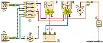
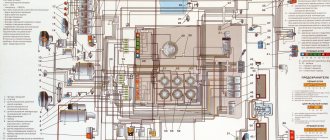
Scheme UAZ-3741, -3909, -3962, -2206 Loaf.
Scheme UAZ-3741, -3909, -3962, -2206 Loaf.
Electrical diagram (without steering column switches).
1 – front lamp; 2 – headlight; 3 – special sign lamp (only for UAZ-3962); 4 – heater fan electric motor (only for UAZ-3962, UAZ-2206); 5 – signal lamp sensor for emergency condition of the hydraulic brake drive; 6 – sound signal; 7 – side turn signal repeater; 8 – turning headlight (only for UAZ-3962); 9 – turning headlight switch; 10 – cabin lighting; 11 – signal lamp for turning on the parking brake system; 12 – switch for the parking brake system warning lamp; 13 – windshield wiper motor; 14 – switch for the electric motor of the windshield wiper and washer; 15 – speedometer; 16 – signal lamp for turning on the high beam headlights; 17 – voltmeter; 18 – oil pressure indicator; 19 – warning lamp for emergency oil pressure; 20 – coolant temperature indicator in the engine cylinder block; 21 – warning lamp for emergency overheating of the coolant in the radiator; 22 – fuel level indicator; 23 – washer motor; 24 – alarm switch; 25 – signal lamp for direction indicators; 26 – emergency signal lamp for the hydraulic brake system; 27 – ignition switch; 28 – central light switch; 29 – thermal fuse; 30 – heater resistance; 31 – heater fan motor switch; 32 – headlight switch; 33 – rear fog lamp switch; 34 – fuse block; 35 – plug socket; 36 – unbalance solenoid valve; 37 – direction indicator switch; 38 – sound signal button; 39 – sensor for emergency oil pressure warning lamp; 40 – warning lamp sensor for emergency overheating of the coolant in the radiator; 41 – oil pressure indicator sensor; 42 – coolant temperature indicator sensor in the cylinder block; 43 – turn signal switch; 44 – heater fuse (only for UAZ-3962, UAZ-2206); 45 – heater fan electric motor switch (only for UAZ-3962, UAZ-2206); 46 – resistance of the heater fan electric motor switch (only for UAZ-3962, UAZ-2206); 47 – heater fan electric motor (only for UAZ-3962, UAZ-2206); 48 – generator; 49 – spark plug; 50 – sensor-distributor; 51 – ignition coil; 52 – ground switch; 53 – rechargeable battery; 54 – lamp switch; 55 – plug socket (only for UAZ-3962, UAZ-2206); 56 – lampshade; 56* – lampshade (only for UAZ-3962, UAZ-2206); 57 – transistor switch; 58 – emergency vibrator; 59 – electronic carburetor control unit; 60 – microswitch; 61 – additional resistance; 62 – additional starter relay; 63 – solenoid valve; 64 – starter; 65 – fuel level indicator sensor in the tank; 66 – brake signal switch; 67 – reverse light switch; 68 – rear lamp; 69 – rear fog lamp; 70 – license plate light; 71 – reversing lamp; 72 – trailer socket.
Source
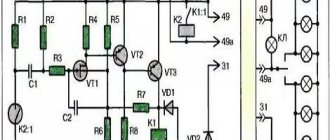
Connection diagram to the starter circuit
Starter activation diagram: 1 – ground switch; 2 – rechargeable battery; 3 – additional starter relay; 4 – ignition switch (lock); 5 – voltmeter; 6 – contact disk; 7 – retractor winding; 8 – holding winding; 9 – starter traction relay; 10 – starter
Starter 42.3708 or 4211.3708–01 with an electromagnetic traction relay and a lever drive with a roller freewheel clutch is installed on the left side of the engine (along the direction of the vehicle). The starter connection diagram is shown in the second picture
Blog about UAZ
To start the engine of UAZ-469, UAZ-469B vehicles and carriage-type vehicles of the UAZ-452 family, an ST 230-B2 starter installed on the left side of the engine was used. The starter is turned on using an electromagnetic traction relay PC 230-B2 mounted on its housing.
Starter ST 230-B2 for the UAZ-469, UAZ-469B and UAZ-452 family engines, design and operation.
The ST 230-B2 starter is a four-pole DC electric motor with sequential excitation and has a rated power of 1.4 liters. With. when powered by a 60 Ah battery.
The starter starts working when the ignition key is turned to the extreme right position. In this case, the electrical circuit of the additional relay PC-502 is turned on, through which current flows from the battery to the starter traction relay PC 230-B2. The traction relay consists of two windings: a pull-in winding and a holding winding.
Under the influence of the electromagnetic field of two relay windings, the armature of the traction relay is pulled into the coil and, using a lever, engages the gear, and at the end of the stroke turns on the starter electrical circuit, simultaneously turning off the retractor winding of the relay. The holding winding of the traction relay remains energized.
After starting the engine and returning the ignition switch key to its original position, the additional relay circuit will open, the holding winding will be de-energized, and the traction relay will turn off under the action of the return spring.
Since the retracting and holding windings of the starter traction relay consume a large current, and the ignition switch is designed for relatively small currents, the starter is turned on through an additional starter relay RS-502.
Starter connection diagram ST 230-B2.
Maintenance of ST 230-B2 starter.
Starter maintenance comes down to periodically checking the condition of the wires attached to it and the starter itself to the clutch housing. It must be remembered that a violation of the tightness of the connection of the wire coming from the battery to the starter terminal leads to an increase in the contact resistance of its circuit and, as a consequence, to a decrease in starter power and deterioration of engine starting.
Once a year, during regular maintenance, it is necessary to remove the starter from the engine, disassemble it, thoroughly wipe it and blow out the parts with compressed air. Replace damaged parts with new ones or repair them. Particular attention should be paid to the condition of the brushes and commutator.
Perform periodic maintenance work on the starter:
1. Check the condition of the clamps, making sure they are not dirty or loosened. 2. Remove the protective casing and inspect the collector, correct any faults if necessary. 3. Open cover 13 (see first picture) from the collector side, inspect and, if necessary, clean the contact surfaces, then blow with compressed air. 4. If necessary, tighten the starter housing pinch bolts. 5. Check the fastening of the starter to the clutch housing. 6. When operating the vehicle in difficult conditions, remove the starter to clean the drive and freewheel from dirt.
Every 32,000 km of the vehicle, perform the following maintenance work on the starter:
1. Remove the starter from the engine. 2. Check the condition of the commutator and brushes. Make sure that the brushes do not jam in the brush holders. If the brush height is less than 6 mm, replace them. 3. Disassemble the starter. Replace worn parts. 4. When assembling, lubricate the bearings and shaft journals with engine oil. Lightly lubricate the splined part of the shaft, drive outlet bushings, pins and lever axis with Litol-24 grease.
When I was looking for why the starter might not work, I found this picture from the instruction manual for UAZ vehicles.
Starter malfunctions and methods for eliminating them:
When the starter is turned on, the armature does not rotate
| Probable cause of the malfunction | Remedy |
| Contact between brushes and commutator is broken | Remove the starter from the engine, disassemble it and eliminate the cause of the malfunction |
| There is no contact in the starter traction relay switch | Disconnect the wires from the starter, remove the switch cover with terminals. If the contacts are burnt, clean them. Rotate severely burnt contacts 180° around their axis |
| Broken connections inside the starter or in the traction relay | Repair the starter in a workshop |
| There is no reliable contact in the ignition switch at terminal “C” | Check the circuit using a test lamp connected to terminal C and ground. If there is no voltage at terminal “C” in the position corresponding to the starter turning on, replace the ignition switch |
| The winding is broken or the contacts in the additional relay are burnt | Check the circuit with a test lamp. The lamp connected to terminal “K” of the additional relay and ground should light up when the starter is turned on. If the lamp does not light, then disassemble the relay and clean the contacts |
| The armature is stuck in the sleeve of the electromagnet coil | Clean the armature, relay and bushing from dirt. If there is displacement of the traction relay relative to the starter lever, have it repaired in a workshop. |
When the starter is turned on, the engine crankshaft does not rotate or rotates at low speed
| Probable cause of the malfunction | Remedy |
| Battery is discharged or faulty | Check the battery and replace if necessary |
| Short circuit of the armature or field coils or the armature touching the poles | Repair the short circuit or send the starter to a workshop for repair. |
| The engine crankshaft is difficult to turn | In winter, warm up the engine |
| The starter power supply circuit is broken due to loose wire ends | Inspect the entire starter power circuit, tighten all clamps |
| Severely worn bearings | Send the starter to a workshop for repair |
When turned on, the starter shaft rotates at high speed, but does not turn the engine crankshaft
| Probable cause of the malfunction | Remedy |
| Broken flywheel teeth | Change the crown |
| Roller freewheel slips | Change the starter drive |
When you turn on the starter, you hear a repeated strong knock of the traction relay and the gear on the ring gear, but the engine crankshaft does not turn
| Probable cause of the malfunction | Remedy |
| There is no reliable contact in the clamps, especially on the battery | Check and tighten clamp bolts |
| Battery is discharged or faulty | Check and charge the battery or replace it |
| The holding winding of the traction relay is faulty or its contact with ground is poor. | Replace the winding or ensure reliable winding contact |
The starter does not turn off after starting the engine
| Probable cause of the malfunction | Remedy |
| The drive jams on the armature shaft | Disassemble the starter and eliminate the cause of the jamming |
| Sintering contacts of a traction relay switch or an additional relay | Fix the problem or replace the relays with new ones |
Self-activation of the starter when the car is moving
| Probable cause of the malfunction | Remedy |
| The locking part of the ignition switch is stuck | Replace the ignition switch |
Replacing the regulator relay on a UAZ 469 (UAZ EM 67370227023702)
Why doesn't the starter work?
A car starter is an electric motor that is powered by a battery and is designed to start a gasoline or diesel engine. For this reason, this device is prone to both mechanical failures and problems in electrical power circuits or problems in the contact area. If the car's starter does not respond to turning the key in the ignition and does not make sounds (for certain problems, the starter clicks or buzzes), then the check should begin with the following:
- determine the full charge of the battery;
- carry out diagnostics of the ignition switch contact group;
- check the traction relay (retractor)
- check the performance of the bendix and the starter itself;
The ignition switch contact group can be checked very quickly. To do this, just insert the key and turn on the ignition. The lighting of the lights on the dashboard will clearly indicate that the contact group is in working condition, that is, you should look for problems in the ignition switch only if the indicated lights on the dashboard do not light up after turning the key.
In the case of a suspected battery, it will be enough to turn on the headlights or headlights, and then evaluate the lighting of the light bulbs on the dashboard, etc. If these energy consumers light up very dimly or do not turn on at all, then there is a high probability of a deep discharge of the battery. You should also check the battery terminals and the ground connection to the body or engine. Insufficient or no contact at the terminals or ground wire will result in severe current leakage. In other words, the starter will not have enough power from the battery to start the engine.
To check the battery on a car with your own hands, you need to remove the negative terminal, after which the voltage at the battery outputs is measured with a multimeter. A reading below 9V will mean that the battery is low and needs to be charged.
The presence of characteristic clicks from the starter when trying to start the engine, which are also accompanied by a noticeable decrease in brightness or complete extinction of the lights on the dashboard, indicates that the solenoid relay is clicking. The specified relay can click both in the case of a discharged battery, and as a result of malfunctions of the retractor or starter itself.
UAZ starter
Good afternoon everyone. I don’t know where to write anymore, the last hope for this forum. The problem is that my loaf broke not long ago, namely, either the relay to the starter went off, or the starter itself. I bought a new starter and relay, installed the starter, but the problem with the relay is that I can’t figure out the wires, the relay is a standard 4-pin relay (the numbers on it are 30,85,86,87.) I found a wiring diagram, it seems like I do everything according to the diagram, but when When I turn the key, the starter does not work, I checked the relay, it is working, I even tried to connect it at home, I took the starter, relay, battery, ignition switch, everything was connected, same story. Smart people, tell me what the problem is, where I'm wrong, I don't understand wiring at all.
The second question is when I start the UAZ using a screwdriver, it runs for a while after starting, and then the starter stalls while it is very hot, what could be the reason??
Well, the last question I have in my head is two 4-pin relays, one is probably for the starter, and the second is why, should there be two or one.
Thank you all in advance for your answers, I will be very grateful for any help.
Additional starter relay, is this a solution to the problem or not.
Dismantling
The location of the starter on the UAZ Patriot is behind the right wheel, in the transfer case area. The mounting bolts are also interconnected with the gearbox bell. The device is removed from below, from the hole - there is no way to crawl out from under the hood, even using long devices.
Tools you will need: wrenches, ratchet with heads, screwdrivers. Before the operation, the battery must be de-energized. It is easier to remove the bottom bolt with a wrench, and the top bolt with a ratchet.
Video: how to remove the starter from a new Patriot
If the starter does not work, it is not necessary to replace it. First, check the serviceability of the traction relay and the condition of the contacts. Then disassemble the device, clean it thoroughly, replace damaged elements and reassemble.
| Khomych | The first frosts (slightly below zero) provoked a problem: At the first start (in the morning), the starter “does not want” to let go of the flywheel and spins with it for another 20 seconds. Subsequent starts (even after a few hours) without problems. The mileage is 4000, the car is parked on the street. |
| Kurusa | The mileage is low, and there are all signs of an oil-filled starter. Disassemble. Wash. Lubricate and assemble according to the manual |
| Field truck | Cool... also the old man will soon be covered |
| For Fun | Replace (starter) under warranty. |
| Vasily Poiko | It was the same crap at first. They replaced it under warranty without any questions. |
| Susikov | The same garbage (short “squeal” of the starter during “cold” starting) appeared at 45,000 km after the entire engine compartment was covered in mud and the starter was “bathed” (forced by huge puddles and water-filled ruts in a dense forest). We removed, cleaned and lubricated the starter - there was still a very short “squeal” on “cold” (silence on “hot”). We'll see. Since the car is new and if it’s still under warranty, I recommend going to the dealer and having them replace it. |
| Dredge | And I had this problem when it was cold: Turn the key, the starter may start turning the engine for a split second, maybe a second, and then it breaks - it feels like it continues to idle, when you release the key, it turns normally again, but lately it’s been trying from 3, 4 it starts to turn normally... When warm and hot there are no problems. What could it be? Doesn't the retractor hold? Could it be that the flywheel crown is turning? By the way, is it whole or not? A friend on Oda was bred just to replace the flywheel, but it turned out to be a retractor... And what kind of starters do we have in general, what might be needed for 2007, Euro2? |
| NATO member | The Pramo is under an Iskra license, a week ago it finally died and was replaced with a new one, there are no spare parts and it’s not profitable to repair it, however. It’s better to replace it, otherwise I stalled while driving to Tula, and all the Moscow and Moscow region jeepers frowned and pouted their lips as if I were offering them to pull the KAMAZ. Only a fellow countryman helped out on Ducato, for which many thanks to him. It's not worth it to just stand there immobilized |
| Dredge | I feel like I’ll have to get a new one... I looked at the Consumer Union and it costs 2500 in total... the retractor is 600 plus... Bendix from 150 to 500. The bushings, windings, everything is there :) By the way, is it very painful to change it? There are no PS protections. |
| Trump77 | yes, it seems to be in plain sight, you can crawl up, although I haven’t tried it myself... Pickup 2012 (s.p.), 409 E4 (E3), HBO Alpha-S4, Toyo OpenCountry MT 32 |
| Lexans | I had the same crap for a long time, I didn’t think about it, I bought a new one, I thought I’d replace the old one. But it was lying around for a year until the one I replaced died. As a result, after 10-20 dives into the water, the replacement one got rusty, so I came out in the morning and the machine didn’t work, I changed it to the factory one in half an hour. and it works, but it was warm as soon as the temperature dropped to +10 it started again, in the end I took it off and assembled one of the two in Zaodsky, retracting it in the cold with a screwdriver, barely pulled it out - how can he let go of the crown if it doesn’t move there. something like this. |
| Dredge | So I have this bullshit - as soon as it got colder than 10, that’s how it started. I can’t “not let go of the crown”, but on the contrary, “loses connection with it” in the process of twisting: Half an hour to change? So, as I understand it, it’s not a particularly erotic activity? It’s just that the memories of removing the starters on Nivas are still fresh)))) Well, let’s see, if the weather is bad, maybe I’ll at least take them off and have a look and draw conclusions. On the Niva I had somehow the opposite problem - I changed the retractor, as it got hot especially in a traffic jam - that’s all - we arrived, we stood smoking, we cooled down, if we stalled, I changed it to Bulgarian and forgot. By the way, on ShNiva I also installed the same Bulgarian one and also everything is zero. |
| Microbush | On the Volga I had a similar problem: the copper washers in the solenoid relay stuck, and the starter spun along with the engine, sometimes I even had to remove the terminal. |
| Dredge | I still understand that the flywheel won’t let go - the retractor shot, the bendix flew out and everything got stuck, I don’t have the strength to get back out because of the rye and other things. But for me, halfway through it can start to idle, sometimes it can engage with the engine again for a short time, or maybe it doesn’t cling anymore, after several attempts it turns normally, this is not clear |
(1 rating, average 4 out of 5)