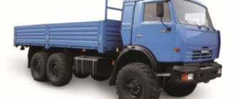
Collection of electrical circuits for the Kamaz truck. Electrical equipment of cars consists of the following systems: power supply, light signaling, external and internal lighting, instrumentation; heating systems, windshield cleaning and sound alarm systems, engine starting. Below are the electrical diagrams of these systems and their descriptions. There are two options - for various modifications of the Kamaz vehicle.
General electrical circuit of KAMAZ models 5320, 5410, 5511
Electrical diagram of KAMAZ light signaling systems
Electrical diagram of KAMAZ power supply and cleaning systems
Electrical circuit of external and internal lighting of KAMAZ
The second option, where the circuits are divided into nodes
Power supply diagram for all Kamaz vehicles with an 800W generator
Power supply diagram for KamAZ vehicles with a 2kW generator
Kamaz engine starting diagram
Electrical circuit of instrumentation
Windshield wiper, heating and sound alarm circuit
Kamaz interior lighting diagram
Electrical circuit of external lighting
Diagram of external light signaling and wheel locking
Trucks from the Kama Automobile Plant are used to transport various goods. The KamAZ 5320 wiring diagram is necessary for repairing and servicing the vehicle. The electrical system of a car refers to a set of devices connected by wires according to a specific circuit.
General information about the scheme
The electrical circuit of KamAZ 5320 is made according to the single-wire principle. The negative contact is the car body. The negative terminal of the battery and the negative terminals of the devices are attached to it. The plus of the battery is connected to consumers using copper wires.
IMPORTANT: To avoid short circuits in the vehicle’s on-board network, the wires are equipped with insulation that is resistant to moisture and temperature changes.
Electrical equipment includes several systems simultaneously:
- External lighting;
- Starting the power unit;
- Power supply for electrical equipment;
- Light signaling;
- Autonomous heater;
- Windshield cleaning;
- Instruments and control lamps;
- Salon lighting.
External lighting
External lighting of the KamAZ 5320 is necessary for using the machine at night. This includes:
- Low and high beam headlights;
- License plate lighting;
- Engine compartment lamp;
- Fog lights;
- A headlight that illuminates the space under the body.
Consumers are included in the electrical circuit through a fuse block. This protects the wiring from fire if a short circuit occurs. To control the system, switches located in the driver's cab are used.
History of the KamAZ-5320 car
The development of the final model of the tractor, which became serial, took more than one year and proceeded in stages:
- 1968 - the prototype of the future classic of the automotive industry was released. It is noteworthy that he was not born at the Kama Automobile Plant. The ancestor of the KamAZ-5320 was the development of the engineers of the Likhachev plant - ZIL-170. The car was designed for operation in extremely difficult conditions in the absence of normal road surfaces, and was intended for transporting cargo for civilian and military purposes.
- May 1969 - road tests of the prototype are carried out with brilliant final results. A section of the road from Uglich was chosen as the test route, and the tests finished in Rybinsk.
- 1969 - members of the USSR Government decided to build an industrial production complex for the construction of automobiles on the territory of Naberezhnye Chelny that met the current requirements of that time. The management also moved the production of the ZIL-170 here, which was reborn into a truck called KamAZ 5320.
- 1974 can be considered the year of birth of the tractor; the first KamAZ-5320 unit saw the light of day. However, mass production of vehicles began a little later.
- February 16, 1976 - the official launch of mass production of the tractor, which for many years became a kind of symbol of domestic cargo transportation.
- 1979 - the plant takes the first global position in the automotive market, earning fame as an auto giant.
See also the article Characteristics and operation of the KamAZ 4310 military all-terrain vehicle
Starting the power plant
The power unit is started by an electric starter with a supply voltage of 24 Volts. The starter is powered by two 12 V batteries. The batteries are connected in series.
The positive wire from the batteries is attached to the starter. The electric starter is controlled via a relay using an instrument switch. You can also read about the KamAZ 6520 PGU.
Technical part and equipment of KAMAZ-5320
The basic onboard model of the KAMAZ-5320 truck was equipped with a standard three-seater cab with sound and thermal insulation. Access to the power unit was achieved by tilting the cab forward. The car's cabin was quite comfortable; the sprung driver's seat was adjustable in length, tilt and weight. Passive safety was ensured by seat belts.
The body was an all-metal welded structure with folding sides. The flooring in the body was wooden. Using a special metal frame, a canvas awning was installed on the body.
The truck was equipped with an eight-cylinder KAMAZ-740 afterburning diesel engine with a power of 210 hp, a V-shaped eight-section high-pressure spool-type fuel pump, a low-pressure fuel pump, a fuel injection system, and a multi-mode speed controller.
The truck was equipped with a dry air filter with a replaceable cardboard element and a clogging indicator. For operation in winter, the engine was equipped with a pre-heater and an electric torch system.
The truck was equipped with a multi-stage transmission consisting of a five-speed manual gearbox and a two-stage divider, allowing for ten forward gears and two reverse gears. There was a synchronizer in 2,3,4 and 5 gears.
The KamAZ 5320 clutch is dry, double-disc, with a friction mechanism and peripheral springs. The clutch was engaged using a hydraulic pneumatic booster. The cardan drive consisted of two cardan shafts; the rear and middle axles used a double gear consisting of bevel and spur gears.
Chassis
The middle axle was equipped with a center differential, the locking of which was carried out using an electric drive.
The truck has a dependent front suspension with semi-elliptic springs with free-sliding rear limit switches. The rear is a balancer on semi-elliptical springs with sliding ends and reaction bars. The main brake system is with a drum mechanism and a two-circuit pneumatic drive.
In KAMAZ-5320, the parking brake is also combined with a spare brake, which is a motor retarder with a pneumatic drive. The trailers are equipped with a combined brake drive system. The presence of an alcohol fuse prevents condensate from freezing. The car's wheels are discless, mounted on five studs, and the tires are radial and pneumatic.
Steering is provided by a mechanism consisting of a screw with a nut and a rack and pinion piston. The gear ratio is 20. The steering mechanism is equipped with a built-in hydraulic booster with an oil pressure of 80 -90 kgf/cm.
Electrical part
The electrical systems and equipment of the vehicle operate from a 24 volt power supply. The car is equipped with two 12-volt batteries with a capacity of 190 A. The power of the generator set is G-273 28/1000 V/W.
Based on the tractor, several other trucks were created, which also became widespread in the domestic and foreign markets:
- Kamaz-5410 is a truck tractor that carries up to 19 thousand kilograms of cargo;
- Kamaz-5511 is a dump truck that carries up to 10 thousand kilograms of cargo. Used in the construction industry;
- Kamaz-53112 is a tractor that carries up to 10 thousand kilograms of cargo;
- Kamaz-55102 is a dump truck designed to be driven with a trailer.
Power supply for electrical equipment
When the engine is turned off, consumers are powered by batteries. They are included in the circuit using a ground switch. The mass is turned off remotely. After starting the power unit, the equipment is powered and the batteries are charged by a DC generator.
The generator is connected in parallel to the batteries and has an excitation winding. To stabilize the voltage at different speeds of the power unit, the system includes a relay regulator.
Light signaling
The system is necessary for safe use of the vehicle on public roads. Using the system, the driver indicates a maneuver for other road users.
Light signaling consists of:
- Rear and front lights;
- Road train lamps;
- Turn signal switch;
- Hazard switch;
- Relays and fuses;
- Brake light switch.
REFERENCE: The light alarm is equipped with a socket for connecting trailer wiring.
Truck modifications
The story of the legendary car does not end there - the design of the base model was improved, some parts of KamAZ underwent changes, modified versions of the tractor were released, images of which are shown in the catalog below:
| Truck tractor | Manual transmission, maximum speed 85 km/h Capable of moving loads up to 13.5 tons of net weight on a semi-trailer, 19 tons on a trailer The maximum permissible weight of the road train is 25.9 tons |
| KamAZ-5510 | Construction dump truck | Mechanical 5-speed gearbox with two-mode divider, heated cargo platform, load capacity 13 tons |
| Long wheelbase tractor | Mechanical 5-speed gearbox with a two-stage divider, load capacity 10 tons on a semi-trailer, 20 tons on a trailer. Designed for operation as a composite road train in difficult road conditions. |
| Dump truck with three-way unloading, grain carrier, modification was developed for agricultural needs | Manual 5-speed gearbox with two-stage divider, load capacity 7 tons, maximum speed 80 km/h |
Heater and wiper
The interior of the KamAZ 5320 vehicle is equipped with an autonomous heater, which allows the vehicle to be used at sub-zero ambient temperatures. The circulation of warm air is carried out by an electric fan. The fan motor has two rotation speeds.
The windshield is cleaned by electrically driven windshield wipers. The windshield wiper motor has two operating modes. The electric motor is controlled using a switch located on the front panel of the cabin.
The cabin is equipped with reliable thermal and noise insulation, soft upholstery, comfortable adjustable seats and other devices that meet modern requirements for aesthetics, ergonomics and occupational safety.
The lifting front facing panel provides easy access to the heater, windshield cleaning and washing devices, electrical equipment, wiring diagrams of electrical and pneumatic systems, and front cab supports.
The facing panel consists of two parts. The lower one has a grille for supplying air to the radiator of the engine cooling system and holes for the headlights; the top one - a grille for supplying air to the ventilation hatch. In the raised position, the facing panel is fixed with two telescopic stops.
The cabin is attached to the frame using two front hinge supports and two rear supports with a locking device.
The lower brackets (Fig. 1) of the front supports are bolted to the first frame cross member, and the upper brackets are bolted to the front floor beam. The upper brackets rotate on pins fixed in the lower brackets. Rubber O-rings are inserted into the holes in the upper brackets to prevent dirt and moisture from getting between the rubbing surfaces of the hinge. Rubber cushions are inserted into the upper bracket housings to soften vibrations transmitted from the frame to the cabin through the front supports.
Rice. 1. Front fastening and cockpit balancing mechanism: 1, 12 - lower brackets; 2, 15 — coupling bolts; 3 - finger; 4 — upper bracket; 4 — front floor beam; 6, 14 — torsion bar levers; 7 — torsion bar lever support; 8 - axis; 9— rear floor beam; 10 - first cross member of the frame; 11 — torsion bar; 13 - rubber bushing
The torsion bars of the cab balancing mechanism are fixed in the holes of the lower brackets, making it easier to tilt the cab forward. The cab tilt angle allowed by the limiter is 42°, and the maximum cab tilt angle required to remove the engine is 60°, but the cab trim panel and bumper must be removed.
The torsion-type cockpit balancing mechanism (Fig. 1) consists of two interchangeable torsion bars with levers. The square end of the torsion bar is pressed into the lower bracket of the front cab support, the other end of the torsion bar is loosely installed in the rubber bushing. The lever is rigidly fixed to the splined end of the torsion bar with a coupling bolt. The upper end of the arm rests against the torsion bar arm support, which is attached to the floor cross beam.
Rice. 2. Rear support of the cabin: a - a of the KamAZ-5320 vehicle; b - KamAZ 4310 vehicle; 1 — leaf spring; 2 — spring pad; c — spring stepladder; 4 — upper bracket; 5 — rubber cushion; 6— locking bracket; 7 — clip; 8 — rubber buffer; 9 — shock absorber; 10 — bottom bracket; 11 — bracket
The rear cab supports (Fig. 2) are leaf springs working with hydraulic telescopic shock absorbers. The front part of the spring is attached with a stepladder and a bolt to a bracket fixed to the frame. The shock absorber eye is fixed in the lower bracket. The upper end of the shock absorber and the spring eye are fixed in the spring cage. The movement of the spring is limited by a rubber buffer, which, when the spring travel is more than 25 mm, rests against the frame. The cabin is secured on the rear supports with a locking device (Fig. 3), consisting of a housing bolted to the longitudinal beam of the cabin, a locking hook, a handle and a safety hook with a spring. The lock bracket (see Fig. 2) is welded to a bracket fixed to the spring cage of the rear cab support. A rubber cushion is installed on the bracket, on which the lock body rests in the transport position of the cab.
When fixing the cabin, the bracket fits into the groove of the lock body, and its hook is engaged by the bracket. A groove made around the circumference ensures that when locking the cab, the lock body is pulled towards the rubber cushion on the bracket bracket. To do this, the locking handle must be set to its highest position. The safety hook locks automatically when the cab is locked. To tilt the cab, it is necessary to turn the handles of both locks to the lowest position, and then remove the safety hook from engagement with the bracket.
Rice. 3. Cabin locking device: 1 - locking device body; 2 - spring; 3 — safety hook; 4 — emphasis; 5 — handle; 6 - hook
The mechanism for tilting the cab of the KamAZ-4310 vehicle (Fig. 4) with a hydraulic drive and manual control consists of a hand pump with a tank, filters and a rotary spool equipped with a handle, a cylinder for tilting the cab and oil lines connecting the pump and the cylinder. A mounting handle is used as the pump handle tire spatula or wheel wrench.
Rice. 4. Mechanism for tilting the KamAZ-4310 cab: 1 - front suspension shock absorber; 2— control handles; 3 — drive handle; 4 - hydraulic pump; 5 - tank; 6 — cabin suspension; 7 — bottom bracket; c - lower stop post; 9 — locking pin; 10 — upper stop post; 11 — cabin longitudinal beam; 12 — extension finger; 13 — upper bracket; 14 — shdralic cylinder; 15 — hydraulic drive; 16 — spar
Rice. 5. Pump for tilting the cab and lifting the spare wheel: 1, 20, 4 - plugs; 2—pump housing; 3 - spring; 5 — safety valve spring; 6 — safety valve plug; 7 — bushing of the injection plunger; 8 — wiper; 9 - finger; 10 — pump handle; 11 — pressure finger; 12 - injection plunger; 13 - plug; 14 — filler neck; 15 - safety valve; 16 — tank; 17 — spool handle; 18 — reversible spool; 19 — spool; 21 — pump jet; 22 — protective filter; 23 - suction filter
The cab tilting and spare wheel lift pump (Fig. 5) is a plunger type, with reservoirs, installed on a bracket located on the right side member of the frame behind the cab.
Rice. 6. Cabin tilting cylinder: 1 - cover nut; 2 — wiper; 3 - plug; 4, 16 - half rings; 5 — upper bushing; 6, 21 — support rings; 7, 15, 22—cuffs; 8 — bend washer; 9 - nut; 10 — traffic jam; 11 — washer; 12 — lower bushing; 13, 23 — pressure rings; 14, 19 — sealing rings; 17 — cylinder glass; 18 — cylinder rod; 20 - cylinder cover
Two holes with conical threads are made in the pump body, to which are connected the fittings of the oil lines connected to the cabin tilting cylinder. Oil is supplied to the corresponding fitting by turning the control spool using a handle that is moved all the way in one direction or another. The spool handle is equipped with adjusting stops, which are locked with nuts. Possible handle positions are shown on the instruction table located on the pump body.
For safety, when lowering the cabin, the return of oil from the hydraulic system to the reservoir occurs through a nozzle with a tube, the outlet end of which is located below the oil level.
The reservoir is secured with screws to the pump housing. The tank has a filler neck and a safety valve that limits the pressure in the tank cavity to 20...30 kPa (0.2...0.3 kgf/cm2) and prevents the ingress of dust and dirt.
The cabin tilting cylinder (Fig. 6) is equipped with two safety valves, which, if a hose ruptures or other damage to the system causes rapid lowering of the cabin, closes and the lowering of the cabin stops. The valves also close when the oil supply is too sudden; in this case, to open the valve, it is necessary to turn the spool handle to the position opposite to the position of the operation being performed (if the cabin was raised, then the handle must be set to the lowering position), and then continue lifting in the same position.
The cab lift limiter is located on the right side of the cab. The lower strut of the limiter rotates in a bracket fixed to the right side member of the frame, the upper strut together with the extension - in a bracket fixed to the longitudinal beam of the cabin floor. When the cab is raised, both pillars prevent the cab from spontaneously lowering. To prevent accidental folding of the limiter, a locking pin is used, which is inserted into the holes of the upper and lower posts. Before tilting the cab, it is necessary to brake the vehicle and place the gear shift lever in the neutral position. Then turn the handles of both cab locks to the lowest position and disengage the safety hook of the right lock. By placing the handles on the pump in the cabin lift position and pumping the pump handle with a mounting blade, tilt the cabin to the first position (36°). To prevent accidental lowering of the cab, secure the limiter posts with a locking pin. To lower the cabin, you need to remove the locking pin, set the handles on the pump to the lowering position and pump the pump handle with a mounting blade.
Rice. 7. Device for cleaning and washing windshields: 1 — tank filter; 2 — windshield wiper; 3 - tank; 4 — bracket for fastening the tank; 5 — pump mounting bracket; 6 — windshield washer pump; 7 - jet; 3 — windshield wiper blade; 9 — brush lever; 10 — windshield wiper motor; 11 — air motor spool; 12 — window wiper control handle; 13 — windshield wiper control edges: 14 — pneumatic lines
To tilt the cab 60°, remove the front buffer, lift the front trim panel and tilt the cab to the first position. Then unscrew and remove the pin, and use a hydraulic lift to tilt the cabin to the second position.
The wind window consists of two flat three-layer polished triplex glass. The use of such glass increases the safety of the driver and passenger, since upon impact the glass breaks, but the fragments do not separate from the plastic film. The two rear cab windows have high strength, tempered, unpolished glass.
The device for cleaning and washing windshields (Fig. 7) is located behind the front facing panel of the cabin and consists of two pneumatic single-brush windshield wipers, pneumatic wires and two control valves, the left of which combines the control of the wiper and windshield washing. Windshield wipers are powered by compressed air. When the windshield wiper is turned on with the tap handle, compressed air is supplied to the spool, which distributes the air alternately into one or the other cavity of the air motor, the piston of which drives the lever with the brush. When the windshield wiper is turned off in the lower position, the tap handle automatically returns to its original position.
Rice. 8. KamAZ car door lock: 1 - internal handle: 2 - locking bracket;. 3—outer door handle button
The device for washing windshields consists of a diaphragm pump powered by compressed air, a tank and tubes with two single-jet nozzles designed to spray liquid. The device is activated by the left windshield wiper control valve when the valve handle is moved towards itself until it stops (non-fixed position). After lowering the handle, it automatically returns to the third fixed position, and the compressed air enters the diaphragm pump. The liquid in the pump is squeezed out by a diaphragm to the nozzles, through which it is sprayed onto the glass. After the pump is activated, the diaphragm straightens, a vacuum is created in the cavity under it and a new portion of liquid is sucked from the tank. Thus, the pump is constantly filled with liquid and ready for action.
Cabin doors consist of external and internal panels. They have rotary windows, glass with a mechanism for raising and lowering, locks with external and internal handles.
The door lock (Fig. is unlocked from the outside by pressing the handle button, and from the inside by turning the handle towards you. The lock body is made integral with the installation wedge that fixes the door in the opening. When closing the door, the wedge fits between the latch bracket and the door opening pillar. hardened, unpolished, moved in guides using single-lever window lifters with a mechanical drive. The window lifter drive has a brake mechanism, thanks to which the glass can be fixed in any given position. Installation and dismantling
locks, power windows and windows must be installed through the hatch on the inner door panel.
The car is equipped with a driver's seat (Fig. 9) and two single seats for passengers. For convenience and to reduce fatigue, the driver's seat has a torsion bar suspension mechanism with a gas-filled shock absorber. Suspension is carried out by a torsion bar installed in the pipe. One end of the torsion bar is tightly fixed, the second is connected to the lever of the suspension stiffness control mechanism. To dampen seat vibrations when driving on rough roads, a gas-filled telescopic shock absorber is used, installed behind the seat back. One end of the shock absorber is fixed to the base of the seat, and the other to the cross member of its frame. Seat suspension travel 88 mm. The suspension is designed for a driver weight of 50... 130 kg. Longitudinal movement of the seat during adjustment is carried out by moving the seat along fixed guides attached to the cabin floor. The seat is fixed in one of ten positions using a stopper. The seat cushion and backrest are made of sponge rubber and upholstered in artificial leather. The left passenger seat is designed similar to the driver's seat, but does not have suspension and is not adjustable. The right passenger seat is a chair with a metal spring frame. It has a mechanism for regulating longitudinal movement, similar to the mechanism of the driver's seat. The backrest can take one of five fixed positions. The seat has two folding armrests.
The cabin heating system is designed to heat the cabin and blow the windshield windows and doors with warm, dry air to prevent them from freezing and fogging.
The heater radiator is placed in a niche of the panel and mounted on the outside, and two fans with electric motors are located in the cabin and are covered with a removable protective cover. The radiator is included in the engine cooling system. Hot liquid ncj enters the heater radiator from the corner pipe located on the upper plane of the block in front, on the right along the supply pipe, through the heater control valve located in the niche of the front panel next to the radiator. The liquid enters the lower part of the radiator, and from the upper part through the drain pipe it goes to the lower part of the radiator of the cooling system. Outside air is supplied to the heater radiator through the grille of the facing panel. After passing through the radiator, the heated air is supplied through hoses to the windshield blower nozzles using two fans. Air is supplied to the feet of the driver and passengers from holes in the lower wall of the air distributors with flaps, with the help of which most of the warm air can be directed to blow off the windows. To blow the glass of the doors, there are special air guide grilles installed on the dashboard on the left and right sides. The heat flow is regulated by a tap or by changing the rotation speed of the fan impellers.
The heater valves and air distributor flaps are controlled by levers located at the bottom of the instrument panel, to the left of the steering column. The upper lever controls the heater valve, and the two lower levers control the flaps of the right and left air distributors. The fan motor switch is located on the instrument panel to the right of the steering column on the switch panel.
Heating efficiency depends on the temperature of the coolant in the engine cooling system. When the liquid temperature is below 75 °C, heating efficiency drops sharply. When the outside air temperature is down to minus 10 °C, to heat the cabin when the car is moving, you should use the pressure of the oncoming air flow, turning on the electric motor only if necessary. At lower temperatures, you should turn on the fan motors at a low speed and, if this is not enough, switch them to the maximum speed mode.
Ventilation of the cabin in the summer can be ensured by changing the position of the rotary vents, the glass of the cabin doors, the ventilation hatch, and also through the hatch located in the front panel of the right side of the cabin.
The fairing is designed to prevent splashing on windows, door handles, and rear-view mirrors when driving a car on a wet highway. The cabin is equipped with two fairings. The fairing is a metal shield that has four brackets for attaching to the side panel of the front part of the cabin.
Interior lighting
The cabin has two lamps designed to illuminate the space inside the cabin. The devices are equipped with backlighting, which allows you to monitor the operation of the vehicle’s components and mechanisms in the dark.
ATTENTION: The KamAZ 5320 electrical wiring diagram has wires painted in different colors. This makes it easier to repair and maintain electrical equipment.
From the above it follows that the KamAZ 5320 wiring diagram is colored, intended for repair and maintenance of electrical equipment of a truck. Thanks to the color scheme, the installation of the car's electrical wiring is carried out independently.
Maintenance Features
Like any other vehicles, the KamAZ 5320 truck tractor requires regular maintenance. Careful monitoring is necessary to check all machine systems, the failure of which can cause an accident and failure of the tractor. From the moment of the start of active operation, after a certain period of time, each car is sent for maintenance service:
Maintenance of KamAZ 5320
- after the first thousand kilometers have been traveled, mandatory technical maintenance is provided;
- another 7 thousand kilometers, according to the rules for using equipment, are the basis for handing over the KamAZ for service;
- After 12 thousand or more km, the car undergoes deep preventative maintenance.
Maintenance involves checking all mechanisms and electrical systems, installing and dismantling specific components, and lubrication of all connecting elements. Thus, the machine not only remains in good working order, but also maintains a good appearance. Unlike foreign analogues, servicing domestic KamAZ trucks is much cheaper.
Spare parts are always available on the transport service market, due to the widespread use of models from the Kama plant. Equipment repair can be done either at a service station or independently. Considering the fact that today all truck tractors in this range are used, preventive checks should be carried out as often as possible.
Need for documentation
Practical
Note! Owners not only need the electrical circuit itself, but also accurate information about where exactly the KAMAZ 5320 electrical wiring is laid, as well as factory instructions, visual diagrams and photos in order to service it themselves.
After all, the scope of application of this car is very wide:
- From cities and towns of the European part of Russia;
- Regions of the Far North and the Arctic;
- Hot climate of Central Asia;
- To the tropics and subtropics of other countries and continents.
Factory layout of wiring relative to the supporting frame of KamAZ 5320
Accordingly, operating conditions have a direct impact on the durability of the insulation and contacts of electrical wires and connections, therefore the wiring diagram of the KAMAZ 5320 and its location relative to the body elements is very important when servicing yourself.
Location of electrical wires inside the KamAZ 5320 cabin
In the same way, you may need a useful and necessary wiring diagram for KAMAZ 5511, the most popular dump truck, which you can also find in the corresponding section dedicated to vehicles of this brand.
Historical
In addition to operators, there is a separate category of truck consumers who also need factory documentation.
- restoration workshops;
- exhibition halls;
- museums.
The very “first” KamAZ 5320 - restored and exhibited in the factory museum
Automobile Manufacturer Museums
For reference: the KamAZ 5320 truck with chassis number No. 0000001, according to the order, went straight from the factory assembly line to work in one of the vehicle fleets of Bashkortostan back in 1976.
When the plant in Naberezhnye Chelny increased its volumes several years after the launch of mass production, the question arose about preserving commemorative copies of the produced models. As a result of this decision, a museum was organized, which began searching for and returning particularly valuable exhibits.
KamAZ cab layout
Are you interested in KamAZ cab layout? Call the office with the request “KAMAZ cab layout”, we will advise you on types of payment, price, shipping to your destination. The KamAZ cabin appears as a metal “box” installed above the engine. Since KamAZ vehicles are used in many industrial areas of Russia - mechanical engineering, nuclear energy, agro-industrial complex, automotive industry, military-industrial complex, specialists have created various types of cabs. Today, the KamAZ company produces cabins of various equipment with and without a berth, with a regular and raised roof, double and triple. Since 2009 Restyled cabs began to be installed on trucks. The designers installed plastic door handles, modified the headlights, turn signals, a plastic bumper, dimensions, modified the appearance of the fairing, which resulted in less staining of the door panels, updated the mirror system, installed seats fixed on air suspension, a steering wheel and a column that height and tilt adjustable, “Borovskoe” windshield across the entire width of the cabin, “fresh” instrument panel. In general, engineers have seriously improved the aerodynamic properties, exterior and interior design. Well done!
In the Russian Federation, the climate for body structures is harsh, most of all in autumn and spring, when the temperature is approximately 0 and there is a lot of moisture. Constantly moisturizing body parts leads to corrosion, which is why rust appears. At some point, the owner of the truck thinks about “buying a new Kamaz cab or repairing the one installed on the tractor.” Our employees advise repairing and restoring, since a repaired cabin is 30-55% cheaper than from an assembly line. In our company, major repairs of the Kamaz cab are carried out in accordance with the general required technical standards. The repair processes include: new high-quality painting of cabin parts, disassembly, replacement of damaged parts, erasing old paint. Repairs are carried out by professional workers using modern equipment. When repairing with us, you have a repaired cabin of comparable quality to a new one. By requesting “KAMAZ Cab Diagram”, you will receive the best service. We will ship to anywhere in Russia: Nevinnomyssk, Artyom, Donetsk, Belebey, Aktau, Bryansk, Krymsk, Ufa, Almaty, Novosibirsk, Volokolamsk, Barnaul, Arkhangelsk, Alexandrov, Izhevsk, Lipetsk, Dnepropetrovsk, Kokshetau, Odessa, Ust-Kamenogorsk, Mariupol, Chita, Tyumen, Rostov-on-Don, Volgograd, Tula, Elista, Yurga, Nizhny Kirov, Moscow, Voronezh, Penza, Pavlograd, Gubkin, Novocheboksarsk, Vorkuta, Sochi, Saransk, Krasnoyarsk, Belogorsk, Krasnodar, Meleuz, Syzran, Vidnoye , Pavlodar, Kharkov, Orenburg, Rog, Veliky Norilsk, Samara, Ulyanovsk, Irkutsk, Yaroslavl, Belgorod, Chelyabinsk, Vologda, Klimovsk, Abakan, Nizhny Tolyatti, Brest, Odintsovo, Yakutsk, Pervouralsk, Soligorsk, Kursk, Khabarovsk, St. Petersburg , Azov, Veliky Astana, Saratov, Tagil, Murom, Ustyug, Balakovo, Novgorod, Novgorod, Kumertau, Yekaterinburg, Nizhnevartovsk, Ust-Ilimsk, Novocherkassk, Balashikha, Krivoi Yuzhno-Sakhalinsk, Tambov, Vladimir, Cheboksary, Ryazan, Stavropol, Orekhovo- Zuevo, Omsk, Tomsk, Orel, Kazan, Taldykorgan, Perm, Grodno, etc.
The KamAZ cab that was in an accident
Refurbished KamAZ cab
KamAZ cab cost
How much does a KamAZ cab cost?
How much does a KamAZ cab weigh?
Restyled KamAZ cabs