The brake mechanisms are of a drum type system with two internal pads, the diameter of the brake drums is 400 mm, the width of the linings is 140 mm.
Front brake chambers are diaphragm, for KAMAZ 65115 vehicles, type 30, for other models, type 24; rear brake chambers - for KAMAZ vehicles model 43253 type 24/24, for other models type 20/20.
The drive of the service brake systems is pneumatic, separate. Number of receivers 5, total volume 100 liters. Nominal pressure in the pneumatic drive (6.5-8.0 kgf/cm2).
Adjust the stroke of the brake chamber rods if the value exceeds 40 mm. Depending on the stroke of the rod, the gap in the brake mechanisms between the brake lining and the drum changes. The brake drums should be cold and the parking brake should be off. Adjust the gap by turning the worm axis of the adjusting lever, having previously loosened the locking plug one or two turns (see Fig. Adjusting the gap in brake mechanisms). By turning the worm axis, set the stroke of the brake chamber rod to 20 mm. It is necessary that the rods of the right and left chambers on each axle have, if possible, the same stroke (the difference is no more than 2...3 mm) to obtain the same braking efficiency of the right and left wheels.
After adjustment, after 2...5 km, check the heating of the brake drums, if necessary, release the adjustment lever one click. Vehicles are also equipped with the installation of adjustment levers with automatic adjustment of the gap in the brake mechanisms between the brake lining and the drum (see Fig. Automatic adjustment lever).
Adjustment of the strokes of the brake chamber rods with an automatic lever should be done when overhauling the brake mechanisms (replacing pads, etc.), when the brake chamber rod is in a completely released state (release the energy accumulator using the parking brake control valve).
Carry out the adjustment according to the diagram (see Fig. Adjusting brakes with automatic levers) in the following order:
Adjustable brakes with automatic levers
To maintain the required pressure of the compressed air supplied from the compressor, as well as to cool and release condensate in the brake system, a water separator and a pressure regulator or a moisture-oil separator, made in conjunction with a pressure regulator, are used.
Adjust the compressed air pressure in the pneumatic drive with screw 2 of the pressure regulator (see Fig. Pressure regulator and moisture-oil separator with pressure regulator). When the screw is screwed in, the amount of adjustable pressure increases, and when turned out, it decreases.
To inflate tires, the pressure regulator has an air bleed valve, closed with cap 1 (see Fig. Pressure regulator and moisture-oil separator with pressure regulator). When bleeding air with a tire inflation hose from the tool kit, connect it instead of the cap, screwing the wing nut all the way, and reduce the compressed air pressure in the pneumatic drive, because when the compressor is idling, there is no air bleed. To reduce pressure, open the condensate drain valve on any receiver or operate the brake valve several times. Monitor the presence of condensate in the receivers daily; if it appears, check the functionality of the pressure regulator or moisture-oil separator. The compressed air pressure in the pneumatic drive must be nominal.
Open the condensate drain taps by moving the pusher to the side (see figure). Do not pull the stem down or push it up. After draining the condensate, bring the compressed air pressure in the pneumatic drive to nominal.
The vehicle's working brake systems are controlled by a two-section valve driven by a pedal.
Anti-lock braking system (ABS) brakes
Thanks to this, cars acquire a number of advantages:
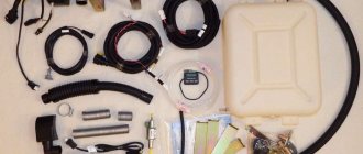
ABS consists of wheel speed sensors, brake pressure modulators, an auxiliary brake release solenoid valve, an electronic control unit, a relay, a fuse box, connecting cables, a diagnostic lamp and a diagnostic key.
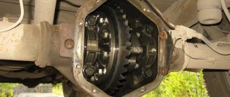
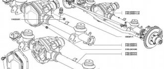
Inductive-type angular velocity sensors installed in the wheels of the front axle and rear axle consist of a gear rotor pressed onto the hub, and a sensor installed in the steering knuckle of the front axle (see Fig. Installing an ABS sensor in the wheel of the front drive axle) or on the bracket of the rear axle axle (see Fig. Installing an ABS sensor in the rear axle wheel).
When the wheel rotates, a variable EMF is induced in the sensor winding, creating an alternating voltage, the frequency of which is proportional to the speed of rotation of the wheel. The received signal is transmitted via cables to the control unit. For normal operation of the sensor, the gap between the rotor and the sensor should not exceed 1.3 mm.
The electronic control unit, together with a protective casing designed to protect the unit from moisture and mechanical damage, is mounted on the front panel of the cab. The block is used to process signals coming from angular velocity sensors, issue control signals to modulators, the auxiliary brake release solenoid valve relay, and diagnostic lamps, as well as for diagnosing system elements.
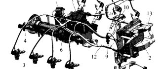
Brake pressure modulators, installed in the brake lines of the front and rear wheels on the frame in front of the brake chambers, are electro-pneumatic control valves that provide precise, stepwise pressure control in the brake chambers, according to commands from the control unit. Modulators installed on the rear bogie control the wheels of the middle and rear axles, located on the same side (i.e., the wheels of the middle and rear axles are controlled by two modulators, located on the left and right sides). Modulators perform the following functions:
When the ABS is not in operation, compressed air flows freely through the modulator.
The auxiliary brake release solenoid valve is installed in the auxiliary brake line and, when braking with the engine brake, serves to disable it in the event of wheel locking.
The auxiliary brake release solenoid valve switching relay is located under the instrument panel in the cab and serves to close the valve solenoid winding circuit when a signal is received from the ABS control unit.
The fuse box, installed to the left of the instrument panel under the folding panel, serves to protect the electrically controlled elements of the ABS.
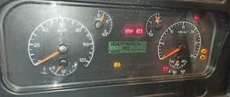
Diagnostic lamps with the symbols “ABS of the tractor” and “ABS of the trailer”, if the vehicle is coupled to a trailer equipped with ABS, signaling the serviceability/failure of the ABS of the tractor or trailer, are located in the upper left corner of the instrument panel (see Fig. Instrument panel).
The ABS diagnostic key, located on the switch panel (see Fig. Instrument panel), is used to activate the ABS diagnostic mode. The key is not fixed, i.e., after pressing it, it must be held for a certain time, depending on the required mode.
System operation
When the power is turned on (when the starter lock key is turned to the “instrument” position), diagnostic lamps with the symbols “Trailer ABS” and “Trailer ABS” turn on; if the vehicle is coupled to a trailer equipped with ABS (see Fig. Instrument panel), automatic test control of the electronic unit and electrical circuits of sensors, modulators and switching devices.
If the system is working properly, the lamp with the symbol “ABS of the tractor” goes out when starting to move, when the vehicle reaches a speed of 5-7 km/h, if the ABS has just been connected, or after completing the self-diagnosis, if the system has already been used. Similarly, the lamp with the “Trailer ABS” symbol goes out if the vehicle is coupled to a trailer equipped with ABS.
If a malfunction occurs in the system or electrical circuits of one of the elements (sensors, modulators, etc.) or control circuits, the diagnostic lamp with the ABS symbol lights up. In this case, it is possible to turn off the corresponding ABS circuit (see Fig. Functional diagram of a vehicle's ABS), and the braking system operates as usual (without ABS mode).
The system does not require special maintenance, except for checking the operation and checking the installation of ABS sensors when adjusting or replacing bearings in wheel assemblies or changing brake linings (if the hubs are removed).
If the diagnostic lamp with the ABS symbol does not go out at a speed above 7-10 km/h, or after eliminating the malfunction identified by the flashing code (see table. Light codes for the status of ABS elements), you should contact a service station to have the malfunction resolved.
When carrying out repairs and troubleshooting, it is necessary to turn off the engine and turn off the power to the system. The system power is turned off when the starter and instrument switch key is turned to the “off” position and the ground switch is turned off;
It is strictly forbidden to carry out welding work on a vehicle with the electronic unit installed. In this case, the electronic unit must be disconnected and removed from the vehicle.
Functional diagram of a car's ABS
Forced ABS diagnostic mode
ABS has built-in self-diagnosis; the system continuously monitors its own performance. To force a performance check for troubleshooting purposes, you must enable the forced diagnostic mode.
The electronic unit is turned on in the forced diagnostic mode by pressing and holding down for 1 - 2 seconds the ABS diagnostic key (see Fig. Instrument panel) with the ground switch and the starter and instrument switches on (the lock rotor must be turned the key to position “I”.
Moreover, if the diagnostic lamp was on before entering the diagnostic mode (which indicates the presence of active errors, i.e. errors or malfunctions present at the time of diagnosis), then when you press the button it goes out for about 1 second, and then a cyclically repeating signal is displayed active error code every 4 seconds until the problem is eliminated.
The light flashing code of an active error about the nature of the malfunction and the faulty system element consists of two information blocks, which are two blocks of light flashes. The duration of each flash is 0.5 seconds, the pause between flashes is 0.5 seconds, between blocks is 1.5 seconds. The faulty component and the nature of the fault are determined by the number of flashes of the diagnostic lamp in the first and second blocks, respectively, according to the table Light codes for the status of ABS elements. If there are no failures or malfunctions, a light code 1-1 is issued (one flash of the warning lamp in each information block). If there are several active errors in the system, then after the first error is eliminated, a light code for the second active error will be displayed, etc. (until all faults are eliminated).
After eliminating all active errors, it is necessary to turn the lock rotor in the starter and instrument switches with the key, first to position “0”, and then to position “I”.
If there are no active errors, then in the diagnostic mode, light codes of the last 4 passive or “floating” errors are displayed sequentially (every 4 seconds), i.e. errors that existed, but are not present at the time of diagnosis (or were not erased in block memory). Information about passive errors is displayed once. To re-display the passive error light code, you must press the diagnostic button again as described above.
System control mode
In system mode, the system configuration can be determined, the last four (passive) errors from the memory of the electronic unit can be erased, and the system can be reconfigured.
To activate the system mode, you must press the diagnostic key (see Fig. Instrument panel) and hold it on for 3.0 to 6.3 seconds. When the system mode is activated, all passive errors are automatically erased if they were in the unit’s memory. This will be indicated by 8 rapid (0.1 second duration) flashes of the diagnostic lamp. If there are active errors, then the indicated blinking will not follow, and the configuration code will be issued immediately.
The configuration light code is issued after activating the system mode (KAMAZ vehicles have a 4S/4M type system with 4 sensors/4 modulators), the number of lamp flashes should be equal to 2 (two light flashes lasting 0.5 seconds with a pause of 1.5 seconds). The configuration code is repeated every 4 seconds. To exit the system mode, you must turn off and turn on the starter and instruments switch to the “instruments” position or press the diagnostic button for a period of time from 6.3 to 15 seconds. In this case, the output of light codes to the diagnostic lamp stops.
If erasing a fault code is difficult (after repeated erasing operations the same code is retained), you must once again make sure that the corresponding malfunction has been eliminated and repeat the operations until code 1-1 is obtained.
Light codes for the status of ABS elements
Trouble-shooting
The cause of a malfunction of the brake system can be a failure of the pneumatic devices, violation of adjustments, as well as leaks of compressed air in the pneumatic drive due to leaks in the connections of pipelines and flexible hoses. Leaks in the pneumatic drive circuits are indicated by illuminated warning lamps (see Fig. Instrument panel and Warning lamp units) and a buzzer. When the pressure in the circuits reaches above 450–550 kPa (4.5–5.5 kgf/cm2), the lamps should go out and at the same time the buzzer should stop sounding. The time for filling the receivers with compressed air to the nominal pressure should not exceed 8 minutes at the nominal engine speed.
Check the tightness of the pneumatic drive at the rated pressure, the compressed air consumers are turned on and the engine is not running. Locate large air leaks by ear. Minor leaks can be detected by coating the pipe connections with soap emulsion.
When troubleshooting, use the Diagrams of the pneumatic drive of brake systems, which conventionally depict the brake devices and pipelines connecting them.
Diagram of the pneumatic drive of the brake systems of single KAMAZ vehicles models 53229, 55111, 6511 5
Diagram of the pneumatic drive of the brake system of KAMAZ vehicles models 55111, 65115, working with a trailer
KamAZ ABS error codes: diagnostics, how to fix the fault
The operating principle of the system is based on measuring and comparing wheel speed and generating a command to control the brake elements based on signals from the ECU. The output signal is generated in the event of data on different wheel speeds and affects the modulators, which ensures stability and controllability of the truck during braking.
Scheme
Most often, KamAZ uses an ABS scheme built on the principle of 4 sensors and 4 modulators. This makes it possible to act on the braking elements of all wheels. The rear bogie modulators control the wheel brakes on one side of the middle and rear axles. At the same time, they increase and maintain pressure in the brake chambers, and, if necessary, release it.
When one front wheel is locked, the system changes the pressure in the front brake chamber of the other in steps. During braking mode, the engine brake is activated. When skidding, it is disabled, but if the solenoid valve wire breaks, it can negatively affect both the operation of the ABS and the braking mode.
How to install
Installation of ABS on KamAZ is carried out only in specialized workshops that have permission for this type of activity. Independent intervention in the design of the brake system is strictly prohibited.
How to disable
The easiest way to disable the anti-lock braking system is to remove the fuses or disconnect the sensor connectors. However, this is not recommended due to the fact that a functioning system reduces the braking distance and prevents the car from skidding.
Based on how the anti-lock braking system is designed, we can easily conclude that the lamp can be on for the following reasons:
All of the above can lead to the ABS light coming on when the car is moving. For example, vibrations caused by an uneven road very often lead to a break in the wiring. When driving on bad roads or where there are no roads at all, the sensors may become covered with dirt and sand.
This will not allow them to transmit the correct information to the electronic unit and will cause the light to remain on.
Types of ABS sensors
On modern cars, the three most common types of ABS sensors are:
- passive type - its basis is an induction coil;
- magnetic resonance - acts on the basis of changes in the resistance of materials under the influence of a magnetic field;
- active – works on the principles of the Hall effect.
Passive sensors begin to work as soon as movement begins and read information from a toothed pulse ring. A metal tooth passing by the device provokes the generation of a current pulse in it, which is transmitted to the ECU. The sensors come into operation at a speed of 5 km/h. Pollution does not have any effect on their operation.
Active sensors consist of electronic components and a permanent magnet located on the hub. When a magnet passes by a device, a potential difference is formed in it, which is generated into a control signal for the microcircuit. The data is then read by the electronic control unit. Such ABS sensors are extremely rare and cannot be repaired.
Passive type of ABS sensors
A simple and reliable device with a long service life. Does not require additional power. It consists of an induction coil inside which a magnet with a metal core is placed.
When the car moves, the metal teeth of the rotor pass through the magnetic field of the core, thereby changing it and forming alternating current in the winding. The higher the vehicle speed, the greater the frequency and amplitude of the current. Based on the data received, the ECU gives commands to the magnetic valves. The advantages of sensors of this type include low cost and ease of replacement.
Disadvantages of a passive ABS sensor:
- relatively large size;
- low data accuracy;
- does not start working at speeds up to 5 km/h;
- triggers at minimal wheel rotations.
Due to constant malfunctions, it is rarely installed on modern cars.
Magnetic resonance ABS sensor
Their work is based on the ability to change the electrical resistance of a ferromagnetic material under the influence of a constant magnetic field. The section of the sensor responsible for monitoring changes is made of two or four layers of iron-nickel plates with conductors placed on them. The other part is installed in an integrated circuit and reads changes in resistance creating a control signal.
The rotor with this design is made of a plastic ring with magnetic sections and is rigidly fixed to the wheel hub. When the machine moves, the magnetic sections of the rotor affect the magnetic field of the plates of the sensitive element, which is recorded by the circuit. A pulse signal is generated and transmitted to the control unit.
The magnetic resonance ABS sensor detects changes in wheel rotation with high accuracy, which increases vehicle safety.
Based on Hall effect
Its operation is based on the Hall effect. A transverse potential difference is formed at different ends of a flat conductor placed in a magnetic field.
In sensors, such a conductor is a square metal plate placed in a microcircuit that includes a Hall integrated circuit and controls the electronic circuit. The ABS sensor is located opposite the impulse rotor. The rotor can be made entirely of metal with teeth or in the form of a plastic ring with magnetic sections, and is rigidly mounted on the wheel hub.
In such a scheme, signal bursts are constantly generated at a certain frequency. In a calm state, the frequency is minimal. When moving, metal teeth or magnetic areas pass through a magnetic field and cause a change in current in the sensor, which is monitored and recorded by the circuit. Based on this data, a signal is generated and transmitted to the ECU.
The sensors come into operation immediately after movement begins, are highly accurate and ensure reliable operation of the systems.
Purpose of the anti-lock braking system
ABS is installed on many KamAZ models for better control of the braking system (on such trucks it is pneumatic). KamAZ trucks have different types of braking: service, parking, spare, auxiliary braking, emergency brake release. The anti-lock braking system prevents the wheels from locking when braking, which improves controllability, avoids skidding, and stopping the car becomes smoother. Also, the presence of ABS is important to increase the average safe speed at different clutches.
Types of ABS
Different KAMAZ models use German (Wabco, Knorr Bremze) and Belarusian “Ekran” anti-lock braking systems.
There are several types of ABS:
- single-channel – release of the brakes on all wheels when one is blocked
- two-channel – axis adjustment using a low-threshold or high-threshold wheel
- three-channel – the rear wheels are controlled from this channel, the front wheels are controlled from individual
- four-channel – each wheel is controlled via its own channel
Let's sum it up
As you can see, the ABS system is not particularly complex in terms of design, but it performs important functions and directly affects safety. For this reason, it is recommended to carry out preventive diagnostics of ABS, as well as eliminate any failures and malfunctions of the system if the slightest sign of trouble occurs.
Why do the brakes on your car squeak, you can hear the brakes grinding, whistling or squeaking when braking: the main reasons. Brake pads squeak, what should the driver do?
ABS is a specially designed system that sits above the car's braking system and controls its operation. The main function of the ABS system is for the driver to perform optimal braking, without the vehicle going into a skid, despite any unfavorable factors. Therefore, all new cars are equipped with this system, and if there is any brake malfunction, the ABS on the dashboard immediately starts to light up. What can cause problems in the braking system to which ABS responds? Let's look at this issue.
When does the ABS light come on?
A working ABS indication is activated on any vehicle when the ignition is turned on. This is a normal situation, indicating that the electronic “brain” of the car is performing diagnostics, demonstrating to the car owner that the system is operational. Then, within a few seconds, the indicator should go off. If this does not happen, or the ABS light suddenly comes on while driving, it means that there are some problems with the brakes that require an immediate solution.
However, there are cases when the electronics themselves that control braking fail, so you need to look in this direction when looking for the reason for the indicator to turn on. Specific reasons why the ABS light is on:
Eliminating other causes of the ABS light signal
Elimination of loose contacts is carried out by checking them one by one. In this case, the four connectors of the ABS system are located directly behind the brake discs of the wheels, next to the system sensors. The fifth contact is located in the engine compartment, it will not be difficult to find it, focus on the vacuum brake booster.
Repair, in this case, consists of disconnecting and cleaning each of the contacts. After connecting the cleaned contacts, it is necessary to check the operation of the ABS system. If, while driving, the light does not light up, then the cause of the malfunction has been eliminated.
On cars equipped with on-board computers, all errors are not only highlighted on the indicators, but are also recorded by the computer itself, which displays them in the form of a code. You can find out why the ABS light is on in your car using this code by finding its meaning on the Internet.
So, let's summarize. If, while driving your car, the ABS light sometimes comes on or simply does not turn off, and you are unable to resolve this malfunction yourself using the recommendations given, then be sure to contact a car service center. Don't wait for your car's brakes to fail while driving on a busy highway.
The ABS system plays a special role in the operation of the entire vehicle, as it is responsible for safety while driving. Many drivers, without knowing it, use the braking system in the wrong way. As a result, the operation of the ABS system is disrupted, which leads to an accident. Most often, drivers face this problem in winter.
Due to slippery roads, the driver constantly brakes when the car skids. In order to understand the problem when the abs light comes on and what to do in this case, you first need to know how this whole system works.
KAMAZ abs malfunction
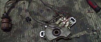
Recently a subscriber from my YouTube channel Sam Sebe Auto Electrician contacted me! In a telephone conversation, it turned out that the car was being repaired at the official KAMAZ technical center in Moscow! And they still cannot fix the ABS fault. Since the technical center did not solve the problem, I will have to solve it. We agree with the client to carry out diagnostics of the abs system. Before connecting to the Kamaz abs unit, we check the abs system using available methods. We check the presence of air in the circuits and press the brake pedal. Then we turn on the ignition and listen to whether the KAMAZ abs modulators work. Since we have a wabco abs unit, the modulators operate in turn. When the ignition is turned on, the abs fault lamp should go out after a short period of time. The abs modulators are activated, the malfunction lamp does not go out!
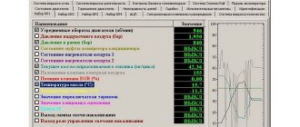
The KAMAZ abs diagnostics begins :) We connect the diagnostic scanner, in my case it is scanmatic 2. The KAMAZ abs errors are as follows: there is no signal from the front abs sensors. We correct the mistakes and ask the client to take a ride. The parameters clearly show that there is no signal from the front abs sensors. KAMAZ front right abs sensor...
mde
After cleaning it a little you can immediately see that it is not inserted all the way. This results in an increased air gap. The abs sensor will not work. Let's take it out...
smartcapture
Judging by the remaining dirt, we can safely say that the air gap was more than 5 mm. We clean everything, including the seat, and put the abs sensor in place. The front right KAMAZ abs sensor is working :)
At the official KAMAZ technical center in Moscow, they said that there are no complaints about the front axle in terms of abs. We didn’t even touch the Kamaz right front abs sensor :)
Let's move on to the front left Kamaz abs sensor. Here you can see that the abs sensor was replaced :) It's new.
smartcapture
But the seat is not cleaned. The retaining bracket has not been replaced.
smartcapture
smartcapture
We also put everything in order. Unfortunately, the left front abs sensor did not work. Why? But the thing is that the front left hub is without a comb :) After replacing the hub, everything worked...
smartcapture
Author
Features of control of KamAZ vehicles equipped with ABS
Drivers driving a car with ABS mistakenly believe that such a system can improve traction, but this is not the case. Due to the fact that the wheels do not lock, controllability is increased and situations where the trajectory of movement can change sharply are prevented.
ABS can eliminate some potentially dangerous moments during braking and reduces the braking distance, but in general, vehicle control remains the same as without an anti-lock braking system.
Almost the only rule of operation is the prohibition of using intermittent braking: the brake pedal must be pressed as hard as possible, all the way. Otherwise, the operation of the ABS may become incorrect and the motion sensors will not respond properly.
The principle of operation of ABS on KamAZ
The electronic control unit constantly receives a signal from the wheel speed sensors. When you press the brake pedal, the control unit receives a signal to start the braking process and, through the truck’s CAN bus, sends a signal to the modulator to turn on the solenoid valves that supply air to the brake pads. Air is supplied to the pads not constantly, but in impulses. As a result of this, the wheels do not skid, but rotate periodically. If any of the wheels hits a section of the road surface with a different coefficient of friction, the system regulates the compression of the brake pads, preventing the vehicle from skidding.
How should an ABS lamp work?
Consists of several functional blocks. This will help you more easily and quickly figure out the problem that is causing the indicator to light up.
The system consists of rotation sensors - there can be two, three or four of them. The system also includes an electronic module or control unit. In addition, the device has a self-diagnosis module and a light indicator on the dashboard.
If immediately after the start or while driving, then this indicates that the anti-lock braking system is disabled. Many drivers mistakenly think that when the light is on there are some problems with the operation of the brake system. This is wrong. The brake system has a separate diagnostic module and indicator. But this only applies to modern cars with good equipment.
In the first few seconds after starting the engine, all the lamps and indicators on the instrument panel light up. If the ABS indicator does not light up when starting, it means there is some kind of malfunction in the system.
Table with errors
Code | Description of two-digit codes |
| 9 | This code on Wabco industrial modules and other versions appears when the on-board control unit EEPROM memory module is faulty. To clear the error, you need to check the quality of the connection with the digital CAN bus. |
| 11 | This code on KamAZ E4 Kamins and other models of trucks and dump trucks indicates a malfunction of the gas pedal. The error is accompanied by the inability of the car engine to increase revolutions above 1900 per minute. To erase this code, you need to check the sensor installed on the pedal, diagnose its connection and clean the connector from dirt. |
| 12, 13 | Decoding codes: problems associated with the operation of the atmospheric pressure controller |
| 14 | Failure of one or more elements of the clutch system. With such an error, the engine does not develop speeds above 1900 per minute. |
| 15 | Malfunctions of the crankshaft, engine speed does not increase above 1600/min. |
| 16, 17 | Frequency sensors malfunction |
| 18 | Malfunctions in the functioning of the camshaft, you need to check the operation of the sensors |
| 19 | The main KamAZ relay must be replaced or repaired |
| 21, 22, 24, 25, 26 | Faulty injection pump (high pressure fuel pump). To eliminate the error, you need to check the device; perhaps water is detected in the filter. The presence of liquid in the fuel will trigger the metering sensor and make it impossible to start the engine. |
| 23 | Incorrect position of the brake or gas pedal. The brake or accelerator pedals may need to be adjusted. Often this error can appear as a result of clogged sensors. |
| 27 | Malfunctions of the steering rack; possible malfunctions of the sensors installed on the steering wheel. If this problem occurs, the engine will not start. |
| 28 | Problems with the brakes. If you manage to decipher that the anti-lock braking system is faulty, then in order to clear the error and determine the cause, you need to check all ABS sensors. A malfunction of ABC controllers may be due to poor contact of the device with the network. |
| 29 | General malfunction code in the operation of the electronic control module, possible causes may be the following:
Prolonged exposure to moisture on the module, which led to oxidation or malfunction of the working board. You need to disassemble the block to find the failed element. |
| 31, 32 | The air flow temperature sensor is faulty or not working correctly. If the device functions, but malfunctions, then the control unit will receive incorrect data on the air temperature. |
| 33, 34 | Malfunctions or failure of the air flow pressure controller |
| 35 | Problems with the cruise control system. It is necessary to check the operation of all sensors, as well as the switch mounted on the steering wheel. The contact may have come loose from the device. |
| 36, 37 | Engine malfunctions: overheating or inability to increase the engine temperature to operating temperature |
| 38, 39 | The fuel does not warm up, which may cause problems with starting the engine. |
| 41 | Multi-stage input signal level does not match reference value |
| 42 | The permissible speed of the power unit is too high and has gone beyond the critical level |
| 43 | The speedometer malfunctions, the device shows the speed incorrectly |
| 51, 52, 53 | Malfunction of the engine control unit |
| 54 | Increased voltage detected in the vehicle's electrical network |
| 55 | General error code in the operation of the engine control unit |
| 61-67 | Communication error due to faulty digital CAN bus controllers |
| 84 | On control units 7uc31 and other versions, this code means a malfunction of the speed controller |
| 97 | Lack of communication with the controller for fixing water in fuel, possible contact closure |
| 99 | General error code in the operation of the engine control unit |
Code | Description of six-digit codes |
| 274179 | Code SPN274179 indicates that the solenoid valve drive shaft is not operating properly. The current detected on the device control line is outside the permissible limits. The problem may be an open or grounded power line. |
| 274192 | The front right wheel front axle controller is faulty, the problem is an open circuit or low signal |
| 274194 | Incorrect position of the driving axis of the distance controller installed on the right |
| 274198 | Front axle sensor failure |
| 520194 | Possible reasons:
|
| 520195 | Possible reasons for this code:
|
| 520196 | Possible reasons:
|
| 520198 | Possible reasons for this code:
|
| 520199 | Malfunctions in the MI driver power supply |
| 520207 | Reasons for the error:
|
| 520208 | Malfunction associated with a break or short to ground or power supply of the power line of the switched power supply of the devices |
| 520211 | Lack of communication or poor contact on the line connected to the ABS system control unit. The problem may be related to the CAN interface. |
| 520222 | Incorrect activation sequence of injector channels |
| 520223 | Microprocessor control device reset error. The cause must be sought in a broken power supply or grounding line. It is noted that this problem arose while the engine was running. |
| 520224 | Control module EEPROM memory error. This self-diagnosis code appears if the EEPROM integrity check procedure was carried out with an error. |
| 520225 | Software version and calibration data version mismatch error |
| 520296 | The efficiency of the neutralizer is below the permissible value of excess toxicity |
| 523352 | Damage or malfunction of the power line of the output stage of the injector control in the second bank |
| 523470 | Malfunction or breakdown of the pressure zeroing valve in the fuel rail. The problem may be a violation of the integrity of the wiring or a short circuit in the power line. |
| 523601 | A critically low or high signal is sent from the refrigerant pressure controller to the control unit, which does not correspond to the standardized values |
| 523612 | Possible reasons for the error:
|
| 523613 | On KamAZ 53504, 53605, 5490 and other versions, this code means a failure or breakdown of the pressure control valve in the fuel rail |
| 523615 | Malfunction of the high pressure fuel pump metering unit. When searching for the cause, it is necessary to check the channel of the analog-to-digital converter for dispenser control, as well as the width-signal control line. The problem is a wiring break or low current on the line. |
Code | Errors in ECU ISB CM2150 |
| 102 | Critically high pressure detected in the turbocharging system |
| 111 | ATS malfunction code of the engine control unit. If this indicator lights up, you need to run diagnostics on the module connection. |
| 115 | The engine speed controller is faulty or not working correctly |
| 143 | Reduced engine fluid pressure |
| 146 | Antifreeze overheating |
| 151 | The refrigerant temperature level cannot increase to the normal value |
| 157 | Possible causes of the problem:
|
| 190 | Incorrect signal (too low) coming from the crankshaft position controller |
| 197 | Lack of antifreeze in the cooling system. If there is enough fluid in the expansion tank, then the problem is with the sensor. |
| 214 | Overheating of the engine fluid or malfunction of the oil temperature sensor |
| 215 | Fuel overheating or fuel temperature sensor malfunction |
| 233 | The pressure in the cooling system has dropped; the problem may be a faulty pump |
| 234 | Increased speed of the power unit |
| 235 | Lack of antifreeze in the cooling system |
| 245 | Low voltage on the control and power lines of the motor cooling fan |
| 261 | Increased fuel temperature |
| 275 | Malfunctions of the high pressure fuel pump device (HPF) |
| 281 | High pressure valve malfunction |
| 351 | Malfunctions of the injector battery |
| 415 | Insufficient engine fluid pressure level |
| 422 | Refrigerant shortage |
| 425 | The engine fluid temperature is increased, the engine may be overheated |
| 428 | Malfunctions of the fuel sensor; data on the volume of fuel may be displayed incorrectly on the dashboard |
| 429 | A critically high voltage is detected on the control and power line of the fuel controller |
| 431 | Error in the idle speed sensor, possible damage to the wiring |
| 432 | Idle air controller malfunctions |
| 433 | Insufficient fuel pressure level in the fuel system |
| 434 | Warning about network loss after turning off the motor |
| 435 | Insufficient engine fluid pressure level |
| 441 | Low battery or device overcharging due to generator set failure |
| 442 | Battery overcharge |
| 449 | Increased fuel pressure in the fuel system, possible malfunction of the fine filter |
| 472 | Pressure sensor malfunction; a critically low signal is sent from the device to the control module |
| 595 | Turbocharging speed exceeded the upper critical level |
| 596 | Increased voltage in the vehicle electrical network due to a malfunction of the generator set |
| 597 | This error code may indicate low voltage in the car's electrical system or a malfunction of the brake pedal sensor. The pulse coming from the device does not correspond to the state of the pedal, and the controller may break down. |
| 598 | Critically low voltage in the generator power circuit |
| 611 | Malfunction of the oil separator, short circuit detected |
| 636 | The gas pedal position controller is faulty or malfunctioning, the device may receive an incorrect signal |
| 638 | On KamAZ 65115, 6522 and other versions, this code indicates low power of the eighth cylinder of the engine |
| 639 | Digital CAN bus fault due to poor signal |
| 677 | Loss of impulse coming from the exhaust gas temperature regulator installed in the seventh cylinder |
| 687 | Reduced turbocharger performance |
| 689 | Motor speed controller malfunction |
| 723 | Loss of impulse by the control unit coming from the exhaust gas temperature controller installed in the third cylinder |
| 729 | Broken or damaged power line supplying the crankcase gas pressure controller. You need to check for voltage on the electrical circuit. |
| 789 | On KamAZ 740 and other versions, this code indicates a malfunction of the sensor installed on the first wheel. The control device does not receive a pulse from the controller. |
| 790 | The problem is in the operation of the sensor located on the second wheel of the car; the device does not send a signal to the microprocessor |
| 791 | Malfunction of the third wheel sensor, possible causes of the problem:
|
| 792 | Fourth wheel sensor malfunction |
| 795 | Malfunction of the pressure modulation valve in the anti-lock braking system. If, after replacing the device, the malfunction indicator on the instrument panel continues to light, the problem must be looked for in poor contact. |
| 801 | Failure or malfunction of the retarder control relay. To find the reason you need to do this:
If the tires have been changed, you need to adjust the speedometer to match the new tire sizes. |
| 980 | Refrigerant leak code, possible causes of the problem:
|
| 1139 | Malfunction of the first engine injector |
| 2265 | Malfunction of the starting pump device, the voltage level on the control and power lines is higher than the normalized value |
| 2292 | If this error is on, then the problem must be looked for in a breakdown of the fuel dispenser |
| 2377 | If “autonomy” lights up on the dashboard and the control unit generates this error, this indicates increased voltage on the fan control line |
| 2555 | Increased voltage in the incoming air flow heating system |
| 2973 | Malfunctions of the pressure controller located in the intake manifold |
Code | Description of brake system errors |
| 2182 | Malfunctions or malfunction of the exhaust brake, the problem must be looked for in the primary circuit |
| 2183 | Primary brake error |
| 4308 | Malfunction of the brake system, no exact fault found: incorrect braking power on the third wheel brake. It is noted that with such an error, the vehicle has a long load over a certain period of time, the vehicle suspension is defective. |
Code | Description of trailer control unit errors |
| 4335 | External Sequence Fault - Trailer Control 1 communications timeout exceeded. No signal may be due to module disconnection or electromagnetic interference. It is necessary to diagnose the CAN J939 wires connected to the trailer control module. |
| 4336 | A similar error, only associated with trailer 2. You need to make sure there is no break in the power line or short circuit. |
| 4337 | Malfunction of the trailer control unit due to incorrect pressure regulation. Possible reasons:
|
Code | Errors related to the operation of the pressure control unit |
| 4271 | The exhaust valve of the pressure control unit installed on the wheel is faulty. The module itself is faulty and must be replaced. |
| 4375 | Malfunctions in the operation of the pressure control module for the sixth wheel of the car. The readings between the compression of the block and the supplied air flow diverge. If the pressure module itself is working properly, then it is necessary to diagnose the pneumatic lines for clogging or damage. |
| 4376 | Malfunction of the pressure control unit installed on the first wheel. If the module is working properly, then you need to check the pneumatic actuators between the foot brake unit and the pressure control device - they may be clogged or open. |
Code | Description of sensor faults |
| 0105 | Incorrect pulse or incorrect voltage on the charge air temperature controller control and power circuit |
| 0110 | Broken charge air temperature controller connection cable. If the electrical circuit is intact, then the regulator itself must be diagnosed and replaced. |
| 0115 | Refrigerant temperature controller malfunction or sensor power wire damaged |
| 0116 | Incorrect signal received from the antifreeze temperature regulator. The readings coming from the device differ significantly from the calculated model of the motor temperature. |
| 0180 | Fuel temperature controller malfunction, possible wiring problems |
| 0193 | A critically high signal outside the permissible values recorded on the control line of the fuel pressure controller in the rail |
| 0195 | The cable supplying the engine fluid temperature sensor is broken; wiring problems are also possible |
| 0500 | Break in the control and power lines of the machine speed controller |
| 0559 | This code can be output in 559 format and indicates a faulty accelerator pedal controller. It is possible that the network data received by the control unit from the sensor is invalid or the update rate is incorrect. |
| 1117 | Malfunction or breakdown of the engine temperature controller |
| 1121 | Malfunction of the first intake air temperature controller due to a short circuit of the device |
| 1318 | Exceeding the possible difference in the values of the antifreeze temperature controllers of the motor half-blocks. If both sensors are operational, then the cause of the problem must be sought in problems with the fuel equipment and cooling system. |
| 1761 | Malfunction of the urea sensor - shorted wiring or incorrect readings coming from the device |
| 2210 | The NOx controller is faulty; the problem must be looked for in the first bank of the engine. The reason may be in the heater control system and is associated with a low input pulse level. |
| 2497 | Malfunction of the main pressure limitation valve, the device freezes in the open position |
| 2623 | Malfunction of the gas pedal sensor or an incorrect signal is received from the device to the engine control unit |
| 2740 | Malfunction or poor connection of the machine speed controller |
| 3046 | Malfunctions of the atmospheric pressure controller |
| 3047 | Failure or incorrect operation of the fuel temperature sensor |
| 3048 | Fuel temperature controller malfunction |
| 3051 | Malfunctions of the fuel temperature sensor, an incorrect signal is sent to the control unit |
| 3089 | Failure or incorrect operation of the charge air temperature controller before entering the cylinder. It is necessary to check the voltage level, power supply, as well as the regulator signal. |
| 3226 | Malfunction of the NOx controller installed at the outlet of the aftertreatment system. The data coming from the device is reliable, but exceeds the maximum permissible values. A detailed diagnosis of the sensor and the wiring connected to it is required. To reset the error, you may need to clean the device's power supply. |
| 3360 | Malfunction of the sensor installed in the catalyst tank. The information coming from the controller is reliable, but the supplied data is below the normal value. |
| 3601 | Weak pulse from the refrigerant temperature controller |
| 3973 | Malfunction of the charge air regulator installed in the high pressure circuit |
| 3979 | The exhaust gas oxygen volume controller is faulty. If the device is inactive, the regulator must be replaced. |
Code | Fuel system malfunctions |
| P000F | In KamAZ edc7uc31 and other versions of the ECU, this code means activation of the fuel system pressure relief valve |
| P1011 | On EDC7 and other versions, this code means an error in regulating the pressure in the fuel rail, possible causes of the problem:
|
| P1012 | Malfunctions in the pressure sensor circuit |
| P1014 | Low pressure in the fuel rail. If error P1014 occurs, it is necessary to check the integrity of all lines and eliminate the cause of the leak. |
| P1662 | Code P1662 appears when the fuel pump metering control mode is periodically violated |
| P1713 | Violation of the high pressure fuel filter dispenser control mode. To remove this SPN or VPN error, you need to check the operation of the filtering device and make sure there are no problems related to tightness. With such an error, the control unit will dose the fuel incorrectly, which will lead to unstable engine operation. |
| 0087 | The fuel rail pressure is too low and outside the permissible limits |
| 0088 | Critically high pressure in the fuel rail |
| 0184 | Violation of the injection pump dispenser control mode. If this code appears on KamAZ 6520, 65201, 65206 or another version, this indicates incorrect operation of the device at idle speed. |
| 1382 | This code can be displayed as a combination SPN 1382 FMI1. Error 1382 FM1 or FMI 1 on KamAZ EURO 4 indicates a malfunction of the fuel filter on the suction side and is associated with pressure drops. You can reset and reset the physical error after checking the filter or replacing it. |
| 1662 | Violation of the control mode of the high pressure fuel filter dispenser - the dispenser was installed incorrectly |
| 2951 | The code can be displayed as a combination P2951 and indicates a malfunction of the high pressure fuel pump metering mode |
| 3084 | Malfunction of the high pressure fuel pump rack |
| 3362 | Incorrect operation of the fuel supply modes, you need to check the operation of the control modules |
| 3363 | Malfunction of the fuel heater, voltage below the normalized value |
| 3441 | Violation of the high pressure fuel filter dispenser control mode |
| 3613 | Malfunctions in the operation of the fuel pump when the engine is idling; the device readings are outside the permissible limits. To find the cause, you need to test the condition and connection of the elements of the high and low pressure hydraulic circuits. |
Code | Wiring faults |
| P0355 | Damage or breakage of the primary or secondary electrical line for controlling the ignition coil E |
| P2157 | Code P2157 on KamAZ Wabco appears when the supply voltage signal for group D injectors is high |
| 0272 | Damage or breakage of the power supply line to the injector installed in the fourth cylinder of the KamAZ 652, 65117, 65116, 6460 or other version |
| 0275 | A similar problem, only related to the injector located in the fifth cylinder |
| 0352 | Malfunction or damage to the primary or secondary electrical line of ignition coil B |
| 1071 | Damage to the primary power supply line for the cooling system fan. If the wiring is intact, then the cause must be sought in a short circuit to ground or power. If an external fan control module is installed on the car, the reason may be a break in the CAN network or failure of the controller. |
| 1074 | Malfunction of the exhaust brake valve. List of possible causes of the error on KamAZ 65222, 65225 and other versions:
|
| 1231 | Problems with the battery, the voltage in the network does not correspond to the normal values |
| 1242 | Gas pedal malfunction due to poor contact of the sensor or its breakdown. If the device is operational, then you need to make sure the quality of its connection to the electrical network. |
| 1380 | Inability to read data. To find the cause, it is recommended to check all wires connected to the control unit. |
| 1623 | This code literally translates as “incorrect tachograph production shaft speed.” The cause of the problem must be sought in an incorrect update rate or erroneous network data received by the control unit. |
| 1624 | The literal translation is “incorrect tachograph vehicle speed”, the error indicates a malfunction of the vehicle speed sensor. The problem is an incorrect update rate or erroneous data received by the control unit. |
| 1691 | Malfunction of the cruise control system indicator, which can be caused by the following reasons:
|
| 1709 | This code can be displayed as P1709 and it indicates a malfunction of the park and neutral switch. The signal from the device is outside the acceptable parameters. |
| 3068 | Malfunctions in the diagnostic module. The signal coming from the device is too high and outside the acceptable parameters. |
| 3416 | Short circuit on the air humidity sensor control line |
| 3617 | Malfunction in the operation of the multi-stage switch, there is no signal coming from the device |
| 7171 | The steering switch is faulty, the problem may be a broken line or poor contact |
Code | Engine malfunctions |
| 2145 | Malfunctions of the exhaust gas recirculation system, possible valve malfunction |
| 3009 | Critically high engine speed. An overspeed check must be performed. With such a malfunction, the injection operation is blocked until the crankshaft speed decreases. |
| 3050 | Malfunction of the exhaust gas aftertreatment system or lack of impulse coming from the SCR |
| 3063 | The inertia phase was not completed, the last two runs ended incorrectly |
| 4238 | Reduced pressure level in the mixture supply system to the exhaust manifold |
| 4239 | Urea malfunction, possible problems with fuel pressure |
Code | Other four-digit errors |
| 3597 | Problems related to the performance of the SCR control unit. The data coming from the device is inconsistent or intermittent. |
| 4334 | On KamAZ 43118, 43253 and other versions, this code indicates an external sequence error. The waiting time has been exceeded or the control unit has detected erroneous conditions in the communication system with the microprocessor module via the CAN bus. The cause of the problem may be internal problems, disconnection from the CAN bus, or electromagnetic disturbances. |
| 4360 | Incorrect catalyst temperature reading. The readings coming from the controller are outside the acceptable parameters. |
The KamAZ error codes listed in the tables above are considered for the following models:
- 4308 (4x2);
- 4310 (6x6);
- 4355 (6×6);
- 43105 (6x6);
- 43114 (6×6);
- 43118 (6x6);
- 43255 (4x2);
- 43253 (4x2);
- 4326-9 (4x4);
- 44108 (6×6);
- 45141 (6×6);
- 45142 (6×4);
- 45143 (6×4);
- 4910 (4x4);
- 4911 (4x4);
- 4925 (6x6);
- 5320 (6x4);
- 5325 (4×2);
- 53202 (6x4);
- 53205 (6x4);
- 53208 (6x4);
- 53212 (6×4);
- 53213 (6x4);
- 53215 (6x4);
- 53228 (6×6);
- 53229 (6x4);
- 53605 (4x2);
- 5350 (6×6);
- 5410 (6×4);
- 54115 (6×4);
- 5460 (4x2);
- 5490 (4x2);
- 5511 (6x4);
- 55111 (6x4);
- 6460 (6x4);
- 65111 (6x6);
- 65115 (6x4);
- 65116 (6x4);
- 65117 (6×4);
- 6520 (6x4);
- 6522 (6×6);
- 6540 (8x4);
- 65201 (8x4);
- 65206 (6x4);
- 65207 (6x4);
- 65208 (6×2);
- 65209 (6×2);
- 65225 (6×6);
- 65226 (6×6);
- 6580 (6x4);
- 65801 (8x4);
- 65802 (6x6);
- 65806 (6x4).
Features of braking on vehicles with ABS
You can forget about intermittent, smooth braking. The driver does not need to constantly monitor wheel traction. The brake pedal must be pressed not weakly, without sparing any effort. In this case, there is no need to use the motor part. The installation prefers to work independently. In an emergency braking situation, we have to talk about simultaneously pressing the brake and clutch pedals. It is important to disconnect the engine from the transmission. You shouldn't place high hopes on electronics.
Malfunctions and repairs
ABS has a built-in self-diagnosis function. It is turned on by turning the ignition switch to position “I”. In this mode, the functionality of sensors, blocks, connections and system elements is checked. The signal is removed when the car reaches a speed of 7-10 km/h. If it continues to light, then the test is carried out in the forced ABS diagnostic mode.
Error codes
If an inoperative element appears, the warning lamp lights up and the system generates error codes. The defective element is determined by the number of flashes of the indicator. In the forced diagnostic mode, the ECU first displays the last 4 errors that remain in the device’s memory once. The meaning of the code is determined using special tables. For example, the resulting value 2-1 corresponds to a malfunction of modulator B, characterized by a short to ground. The codes remain in the ECU memory.
| First error code | Second error code | Troubleshooting Methods |
| 1 - No mistakes | 1 - No mistakes | The system is fully operational |
| 2 – ABS modulator | 1 – Front right 2 – Front left 3 – Rear right 4 – Rear left | Check the wires to the modulator. There is an intermittent or permanent break in the wires to the intake, exhaust valves or the “common” wire, or a short to negative. |
| 3 – Sensor: increased air gap | 1 – Front right 2 – Front left 3 – Rear right 4 – Rear left | Check wheel bearing runout. Move the sensor towards the rotor. Check the sensor cable and connectors for loose contacts. |
| 4 – Sensor: short circuit/wire break | 1 – Front right 2 – Front left 3 – Rear right 4 – Rear left | Check the wires to the sensor. Open or short to “minus” or “plus” or between the sensor wires. |
| 5 – Lost signal / tire size | 1 – Front right 2 – Front left 3 – Rear right 4 – Rear left | Check the wires to the sensor for loose contact. Check the rotor for damage. Connect another sensor to check. Wheel diameters vary. |
| 6 – Rotor | 1 – Front right 2 – Front left 3 – Rear right 4 – Rear left | Check the rotor for damage. Replace the rotor. |
| 7 – System functions | 4 – ABS lamp | Check the wires for the ABS fault warning light. Was the ABS diagnostic switch pressed for more than 16 seconds? |
| 8 - The electronic unit | 1 – Reduced supply voltage | Check the power circuits and ABS fuses. Reduced supply voltage |
| 8 - The electronic unit | 2 – Increased supply voltage | Check the battery and alternator. Increased supply voltage |
| 8 – The electronic unit | 3 - Internal error | Replace the ABS control unit if the error recurs |
| 8 - The electronic unit | 4 – Configuration error | Incorrect electronics / parameterization |
| 8 - The electronic unit | 5 – Connection to the battery negative | Check the ground on the ABS control unit and modulators. |
When repairing a car, you must remember that the ground switch must be turned off and the system de-energized.
Ways to check functionality
To determine the condition of a part, we will perform a series of steps to diagnose it, moving from simple to complex:
- Let's check the fuses by opening the unit (inside the passenger compartment or in the engine compartment) and inspecting the corresponding elements (indicated in the repair/operation instructions). If a burnt component is found, we will replace it with a new one.
- Let's inspect and check:
- integrity of connectors;
- wiring for abrasions that increase the risk of a short circuit;
- contamination of the part, possible external mechanical damage;
- fixation and connection to ground of the sensor itself.
If the listed measures do not help to identify a device malfunction, it will have to be checked using instruments - a tester (multimeter) or an oscilloscope.
Tester (multimeter)
This method of diagnosing the sensor will require a tester (multimeter), instructions for operating and repairing the car, as well as PIN - wiring with special connectors.
The device combines the functions of an ohmmeter, ammeter and voltmeter
Tester (multimeter) is a device for measuring electric current parameters, combining the functions of a voltmeter, ammeter and ohmmeter. There are analog and digital device models.
To obtain complete information about the performance of the ABS sensor, you need to measure the resistance in the device circuit:
- We lift the car with a jack or hang it on a lift.
- Remove the wheel if it prevents access to the device.
- Remove the cover of the system control unit and disconnect the controller connectors.
- We connect the PIN to the multimeter and the contact socket of the sensor (the connectors for the rear wheel sensors are located inside the cabin, under the seats).
We connect the PIN to the tester and the contact socket of the sensor - We measure the resistance (tester in ohmmeter mode) at the contacts of the device. We compare the readings of the device with the car’s operating manual, where the required parameters should be indicated.
- We check the electrical circuit by ringing the sensor wiring for a possible short circuit.
- We spin the wheel manually and at the same time measure the resistance - the tester readings should change depending on the rotation speed.
- We switch the tester to the “voltmeter” mode and measure the voltage on the sensor - we turn the wheel at a frequency of 1 rev/sec, monitoring the readings of the device. Voltage parameters from 0.25 to 1.2 V are considered optimal, but it should be taken into account that increasing the wheel speed necessarily increases them.
The device readings must correspond to the data specified in the repair and operation manual for a particular vehicle. If the device resistance:
- below the minimum threshold - the sensor is faulty;
- approaches zero - short circuit;
- unstable (jumping) at the moment of twitching of the wire - a violation of contact inside the wiring;
- infinity or no readings - wire break.
Attention! The resistance of the ABS sensors on the front and rear axles is different. The operating parameters of the devices are 1–1.3 kOhm in the first case and 1.8–2.3 kOhm in the second.
Video “Diagnostics of the ABS sensor”
How to check using an oscilloscope (with connection diagram)
In addition to self-diagnosis of the sensor with a tester (multimeter), it can be checked using a more complex device - an oscilloscope.
The device examines the amplitude and time parameters of the sensor signal
An oscilloscope is a device that studies the amplitude and time parameters of a signal, which is intended for accurate diagnosis of pulse processes in electronic circuits. This device detects problems with connectors, broken connections to ground, and broken conductors. The test is performed by visually observing the vibrations on the device display.
To diagnose the ABS sensor with an oscilloscope, you must:
- Fully charge the battery so that during the measurement you can observe voltage drops (jumps) on the connectors or conductors.
- Find the touch sensor and disconnect the upper connector of the part.
- Connect an oscilloscope to the contact socket.
Connecting the device to the ABS sensor connector (1 - toothed disc-rotor; 2 - sensor) - Rotate the suspended wheel (by lifting the car on a jack or lift) at a constant frequency of 2-3 revolutions per second.
- Detect the amplitude of signal oscillations on the device display.
- Rotate the second wheel of the axle and similarly detect vibrations.
The serviceability of the ABS sensor is indicated by:
- equal amplitude of signal fluctuations when the wheels of one axle rotate;
- absence of amplitude beats when diagnosing with a sinusoid signal of lower frequency;
- maintaining a stable, even amplitude of signal fluctuations not exceeding 0.5 V when the wheel rotates at a frequency of 2 rps.
Note that an oscilloscope is a rather complex and expensive device. Modern computer technologies make it possible to replace this device with a special program downloaded from the Internet and installed on a regular laptop.
Video “Laptop instead of an oscilloscope”
Checking a part without instruments
The easiest way to diagnose a device without instruments is to check the magnetic valve on the induction sensor. Any metal product (screwdriver, wrench) is applied to the part inside which the magnet is installed. If the sensor does not attract it, it is faulty.
Most anti-lock brake systems of modern cars have a self-diagnosis function with errors displayed (in alphanumeric encoding) on the on-board computer screen. You can decipher these symbols using the Internet or the machine’s operating instructions.
ABS lights up: what should the driver do?
Having studied the possible causes, let's move on to what to do if the ABS is on. As already mentioned, you can first try to reset the errors by removing the terminal from the battery.
If the driver finds himself in a situation where the ABS lights up while driving, but at the moment, for one reason or another, it is not possible to carry out computer diagnostics, you can try to activate the system as follows:
In some cases, it happens that after these actions the ABS light goes out, that is, the anti-lock braking system is active again. If this does not help, it means that the problem is not an electronic failure, there are more serious faults.
As practice shows, the blocks are quite reliable and often the culprit is the ABS sensor on a certain wheel. Taking into account the fact that on many cars these sensors are constantly dirty, salts and reagents get on them, ABS sensors in an aggressive environment literally rot and collapse after 3-5 years of active use of the car. The solution is to clean the ABS sensor, attempt repairs, or completely replace it.
If the ABS light comes on for a while and goes out while driving, you should inspect the wire connections, the wires themselves, and the contacts. Let’s also add that if after repair the ABS sensor lights up, it often happens that the technicians simply forget to connect the ABS sensor. At the same time, you should check how well the wheel is installed, since for this reason the sensor may transmit incorrect data to the block.
Finally, we note that the most serious problem that causes the ABS sensor to light up on the instrument panel is the failure of the ABS module itself. Both a software failure and damage to the control unit itself can occur. In this case, in-depth specialized diagnostics, repair or replacement of the electronic module is required.
How to remove the ABS sensor from the hub
The car's anti-lock braking system maintains vehicle control during braking. It is triggered by readings from sensors that are installed on the wheel. Over time, indicators may become distorted, wiring cracks, and the control element does not work. As a result, when you start the engine, the ABS warning light begins to signal on the dashboard. How to remove the ABS sensor from the hub and check the functionality and cleanliness of the connections will be discussed in the article.
What types of ABS sensor installation systems are there?
The location and number of controllers depends on the car brand. All classes of passenger cars are equipped with one of two ABS systems:
- Two sensors are located on the diagonal front and rear wheels. The system releases the lock when braking along the axles.
- On every wheel. ABS monitors each wheel individually and prevents locking according to road conditions.
You can find out how many tracking elements are installed on a particular car by checking the technical documentation. In most cases, on the rear axle, the sensor is screwed into the brake caliper from the inside; for the front axle, the element is installed in the steering knuckle. Drivers cannot always see the part even after removing the wheel; it is necessary to place the car on a pit or overpass and provide good lighting.
How to remove the rear wheel sensor
As an example, let's look at the most common method of installing a part on the rear wheel using the example of a Volkswagen passat b4, when the tracking device is installed in the caliper at the rear of the hub. The factory design is secured with a hex bolt. Necessary tools for work:
- jack;
- set of hex keys;
- reinforcement crank or cardan;
Dismantling process step by step.
- Remove the wheel. Behind the caliper you can see the installed sensor; there is a thick black cable going to it.
- Specifically in the Passat model, the part is installed immediately opposite the shock absorber strut; it is difficult to see the element from the ground. It is recommended to use a mirror to determine the location and type of fasteners.
- Clean the fastening area, wash the bolt shaft, and fill with WD-40. If the bolt is soured, you may need to drive the key into the seat while leaning on the stand.
- Place the amplifier on the key and unscrew the bolt.
After removing the bolt, do not remove the sensor by pulling the wire or squeezing the plastic casing with pliers. After 5–7 years of operation, the part becomes stuck in the hub, and removing it is quite problematic.
If you remove the brake disc and caliper, you can press the controller out of the hub using an attachment with a screw-on bolt. If you need to remove the ABS sensor without dismantling the disk, you need to fill the element with WD-40 and carefully install pliers on the steel part of the part. Without pinching the plastic casing, pull it out with rotational movements.
If the ABS sensor is installed on a bracket using the corner connection type, during dismantling you will need to unscrew one bolt securing the bracket to the shock absorber and two bolts in the wheel arch.
How to remove on the front wheels
Getting to the ABS sensors on the front wheels is much easier, since the parts are built into the steering knuckles of the wheels. Dismantling order step by step:
- We dismantle the wheel.
- We release the bolt securing the ABS bracket to the steering knuckle and remove the tracking part from its seat.
- To diagnose the wiring and check the functionality of the part, release the wire fasteners and remove the connector plug.
How to avoid breakdown
Like any other important component of a truck, ABS requires timely diagnostics. It can be done using a special program that shows how this or that part of the system works.
ABS does not require special maintenance; it is checked during scheduled maintenance of the brake system. What should be the preventative measures to help prevent breakdowns? Do not use impulsive braking, especially on slippery roads. Also, the brake pedal should be pressed quite firmly, but without a sharp jerk.
How to view KamAZ errors
To perform the check, use two methods.
- Diagnostics using BC. For each modification of the car, the sequence of actions and procedure may differ - you need to look in the service documentation. The advantage of the procedure is its ease of implementation. The disadvantages include inaccuracy of data.
- Connect an external diagnostic module to the car. This will allow you to accurately determine the cause of the problem. At the same time, special equipment and deep knowledge in the diagnosis of trucks will be required.
Self-turning off the light bulb
Sometimes the functioning of the ABS system goes wrong and in this case there is no need to contact technical service for help. There is a simple way to do this. You need to accelerate on a flat section of the road at increased speed, and then brake sharply. Sometimes this procedure helps restore a faulty system and the light stops lighting up.
If this does not help, then only experts can come to the rescue, who will diagnose the system on a special computer and draw an accurate conclusion as to why the ABS light comes on. You cannot spare money on such a service, since the life safety of not only the driver, but also the passengers who may be in the car depends on it.
Novice drivers are often frightened by the various lights that suddenly light up on the dashboard of modern cars. If ABS, then there is no need to panic. The problem is not the most serious; eliminating it will not require large financial investments.
How much does repair and replacement cost?
Depending on which part of the ABS is broken, the price of the repair service will differ. If an ABS unit breaks down, it can be repaired in Moscow at a cost of 5 thousand rubles. Replacing a unit costs from 4,000, and replacing each sensor will cost from 800 rubles. Repair of camshaft and crankshaft sensors will be more expensive - from 1,300 rubles.
Defects in the operation of sensors can be eliminated without replacement - the cost of repairs starts from 1,300 rubles. The cost of repairs includes diagnostics and installation; in case of replacement, these parameters are discussed separately.
Have you used a KamAZ with ABS? Do you consider such an innovation necessary?
Topic: ABS sensor. Ring gap
Club member
Re: ABS sensor. Ring gap
- View profile
- Forum messages
- Private message
- Diary entries
- View articles
Club member
Re: ABS sensor. Ring gap
- View profile
- Forum messages
- Private message
- Diary entries
- View articles
Super moderator
Re: ABS sensor. Ring gap
Posted by pitjab
- View profile
- Forum messages
- Private message
- Diary entries
- View articles
Club member
Re: ABS sensor. Ring gap
- View profile
- Forum messages
- Private message
- Diary entries
- View articles
Club member
Re: ABS sensor. Ring gap
- View profile
- Forum messages
- Private message
- Diary entries
- View articles
Club member
Service station services
If nothing helps and the ABS light is still on on the panel, you need to use the services of specialists from specialized service centers.
This will cost you much more than in the case of self-diagnosis and repair. However, sometimes this is the only true path. Experienced craftsmen will help you find the source of the problems, determine further tactics and budget for future repairs. Competent diagnosticians will perform tests and detect errors in the operation of the anti-lock braking system, if any.
Thus, in a short period of time, with the help of scanners and specialized devices, you can collect all the important information about the condition of the main components of the vehicle, find errors that will help determine the breakdown as accurately as possible.
What does the error consist of?
The first character is a letter that determines the type of defective system:
- P – malfunction of the power unit or transmission (automatic transmission).
- B – malfunctions in the operation of body systems - airbags, electric windows, central locking, etc.;
- C – malfunctions in the chassis of the vehicle;
- U – errors associated with the interaction of electronic modules.
The second character is a number that determines the specificity of the malfunction:
- 0 – general symbol for OBD block;
- 1 and 2 – personal codes of the car manufacturer;
- 3 – reserved information.
The third character determines the type of failure:
- 1 and 2 – air or fuel supply;
- 3 – ignition unit, system for detecting misfires of the air-fuel mixture;
- 4 – additional emission control mechanism;
- 5 – control of vehicle speed and idle speed;
- 6 – electronic control modules, as well as their wiring;
- 7, 8 – errors in the operation of the gearbox;
- 9, 0 - reserve.
The fourth and fifth digits of the error are a number that corresponds to the serial number of the malfunction.