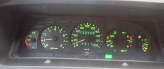
Description and location of indicators and instruments on the panel
In the driver's cabin you can find many incomprehensible devices, the purpose of which must be explained for the correct operation of the vehicle. Each of these devices is located on a special panel, which folds back and is located on the left side of the panel.
The first device where the eye falls is the steering wheel. It is located in the picture below at number 6 and makes it convenient to monitor the readings that are displayed on the measuring instruments in the cockpit. Thanks to the figure below, you can find out the purpose of each button, pedal and lever that are located in the driver’s cab.
Purpose of instruments in the driver's cabin
- Auxiliary (direct) brake control button.
- The pedal is responsible for the clutch.
- A pedal responsible for controlling the brake valve.
- A pedal that controls the start of fuel.
- Air pressure distributor.
- Steering wheel.
- Windshield cleaning device.
- Window lift system lever.
- Gearbox control knob.
- Handle for closing the door.
- Handle for longitudinal movement of the passenger seat.
- Lever for adjusting the backrest of the passenger seat.
- Driver's seat suspension stiffness control lever.
- Engine cable.
- Valve handle for parking and emergency brakes.
- A device that fixes the adjustment of the backrest angle of the driver's seat.
- Fuel supply thanks to manual control.
- The handle responsible for the function of longitudinal movement of the driver's seat.
- Cabin fairing.
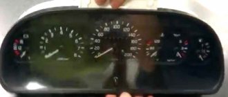
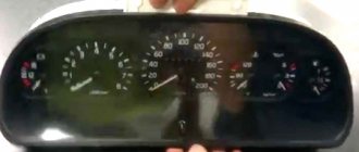
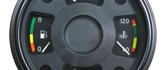
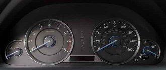
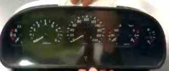
Instrument cluster
Below is how to diagnose problems in advance, as well as the most common breakdowns, including those due to improper use of the cigarette lighter.
KAMAZ blue
A story from repair practice
The instrument panel does not work on KamAZ Cummins
Today is Sunday, the weather is not good again. Cloudy, the sky is densely overcast. Despite the day off, quite a lot of people called today with different problems, I will describe only three. In the morning, an application was received from the city of Vidnoye. A KAMAZ vehicle with a Mercedes Euro 5 engine produced in 2013. Complaints that the instrument panel regularly goes out. The heater and windshield wipers sometimes work, sometimes they don’t, and sometimes the charging indicator light comes on. The fault diagnosis showed low voltage on the on-board network in the vehicle cabin. The foreman cleaned and tightened the mass points; after these measures, the tension returned to normal and the problems disappeared. The owner of the car was very pleased, later he told about the problem of finding a technician for this KAMAZ with this problem, no one wanted to take on this hybrid.
2 Comments
Hello. My KamAZ 5511 instrument panel does not work, the current does not flow there. How to install the ignition switch correctly, which wires should be connected where?
Possible malfunctions and ways to eliminate them
To ensure that no problems arise along the way, it is necessary to diagnose the system for faults before shipping.
Initially, when starting to work with this vehicle, if possible, it is necessary to carry out a quick diagnosis of systems and components. To do this, you need to light the dashboard without starting the engine. Among the indicators that light up, you need to find the lamps that are responsible for the technical condition of the battery and handbrake.
Kamaz 65115
It is also necessary to pay attention to the pressure values in the lubricant system and the glow plug fault sensor. After these simple manipulations, you can take two steps that are both easy and responsible.
- The next time you start the engine, the red indicators on the panel should go out. Only one red lamp should be on. It is responsible for the value of the handbrake. By tightening and releasing the handbrake, you can check the performance of this indicator.
- After a few seconds - from 15 to 20 - the engine can be turned off and the ignition, on the contrary, turned on. When the engine is running properly, the oil pressure indicator will not light up, which means that the pressure has risen to normal. If the engine is in good working condition, then the sensor will light up a couple of seconds after the engine is turned off. If the indicator flashes earlier or almost instantly, this is an alarming sign. Most likely, the motor is pretty worn out (the author of the video is Sergey Sergeich).
If you still have to deal with a breakdown, you need to decide what the reason is.
The most “popular” faults:
- the nozzle stopped working;
- sensors show erroneous values;
- various control mechanisms stopped responding.
Among other things, one option is to use the engine cigarette lighter incorrectly. If the cigarette lighter is used incorrectly, the engine may not start in the future and will have to be replaced.
In case of malfunctions described above, it is necessary to conduct a full-fledged computer diagnostics, which will reveal the presence of failures and various errors.
Features of electrical equipment
Let's start with a description of what elements and subsystems the KAMAZ-5320 electrical wiring removal includes:
- Light signaling and turning lights.
- Heating system, power supply, and windshield cleaning.
- Exterior lighting, including low and high beams, side lights, fog lights, if any.
- Car interior lighting.
- Engine starting system.
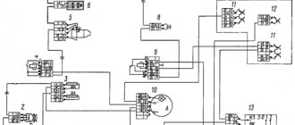
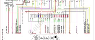
- The wiring diagram also includes a system of control and measuring devices located on the dashboard of the car. The dashboard contains not only a speedometer and tachometer, but also many indicators, as well as sensors designed to provide more convenient control of the car.
- Sound alarm.
- Audio system, if available.
Normal operation of the KAMAZ 43118 electrical circuit is possible only with the correct functioning of two main components:
- Battery. This device provides the ignition system with voltage during engine starting, and also allows you to power the main electrical equipment when the internal combustion engine is turned off.
- Generator. This unit provides power to all devices and equipment while driving a car. The generator also replenishes the battery charge that was spent on starting the engine.
Installation instructions
- For convenience, you can assemble the instrument panel at home, and not directly in the car.
- Install the panel in the cabin using bolts and fasteners.
- After the work has been done, you can work on the deflector tubes. They need to be tightened with clamps.
- When installing the dashboard, you must strictly follow the instructions.
Photo gallery “Step-by-step installation instructions”
You can find out how to assemble a shield at home below.
1. Instrument panel parts
2. Deflector tubes
3. Finished dashboard
Instrument cluster
- Go to page:
#211 Pashka » August 17, 2016, 14:59
Dashboard.
#214 Pan » October 10, 2016, 0:55
The admin will say that if someone knew the reason for certain, they would have already unsubscribed, as this actually happens in other topics. In turn, you didn’t even bother to write down the model of your car and describe (preferably with a photo) its equipment, because... They are made by several cooperatives and the quality and wiring can be very different from each other.
For this malfunction, the only thing that comes to my mind is the missing mass, but I can’t vouch for it.
Autonomy errors 65115
Malfunctions of the KamAZ PGU are indicated by the blinking light on the remote control. The number of flashes indicates the type of error:
| Number of flashes | Malfunction |
| 1 | Replace preheater heat exchanger |
| 2 | Start the engine a little later. |
| 3 | The flame does not break well. |
| 4 | A spark plug or turbine has fallen. |
| 5 | The flame controller is faulty. |
| 6 | The temperature indicator is glitchy. |
| 7 | The pump is depressurized. |
| 8 | The block between the remote control and the motor is faulty. |
| 9 | Low voltage. |
| 10 | Ventilation is complete, but the engine is hot. |
Fuel system malfunctions
The main fault codes for the fuel supply module look like this:
| Code | Designation |
| P1012 | The power supply to the pressure sensor is broken. |
| P1014 | Low pressure in the ramp. |
| P1662 | The fuel dispenser is faulty. |
| P1713 | The problem is with the fuel filter dispenser. |
| 0087 | There is low pressure in the ramp. |
| 0088 | Increased pressure in the ramp. |
| 0184 | The fuel dispenser malfunctions at idle. |
| 1662 | Malfunction of the injection pump dispenser. |
| 2951 | The operating mode of the fuel injection pump is disrupted. |
| 3084 | Replace the injection pump rack. |
| 3362 | Fuel supply modes fail. |
| 3363 | The fuel does not heat up well. |
| 3441 | The injection pump dispenser is faulty. |
Engine errors
The main breakdowns in the operation of the power unit look like this:
| Code | Designation |
| 2145 | The exhaust system is faulty. |
| 3009 | Reduce speed. |
| 3050 | Glitches when neutralizing the exhaust. |
| 3063 | Problems with completing the inertial phase. |
| 4238 | Fuel is supplied at low pressure. |
| 4239 | The urea supply is faulty. |
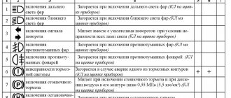
Warning lamps
| Emergency oil pressure in the engine lubrication system (color – red) | ||
| Turning on the high beam headlights (color – blue) | ||
| Activation of the parking brake system (color – red, intermittent) | ||
| Emergency (color – red) | ||
| Low battery (color – red) | ||
| Trailer/semi-trailer direction indicator (color – green, intermittent) | ||
| Vehicle turn signal to the right (color – green, intermittent) | Depending on the vehicle's equipment, the left/right turn indicator lamps may light up simultaneously | |
| Vehicle left turn indicator (color – green, intermittent) | Depending on the vehicle's equipment, the left/right turn indicator lamps may light up simultaneously | |
| Turning on the center differential lock (color – orange). Not available for 4x4 vehicles | ||
| Turning on the cross-axle differential lock on the 2nd axle (color – orange) | ||
| Turning on the cross-axle differential lock for the 3rd axle (color – orange) | ||
| PTO activation (color – green) | ||
| PTO activation (color – green) | ||
| Turning on the traction control system (color - orange) | ||
| Tractor ABS malfunction (color – orange) | ||
| Trailer/semi-trailer ABS malfunction (color – orange) | ||
| Turning on the transfer case center differential lock (color – orange) | ||
| Malfunction in the engine management system (color - orange) | ||
| Malfunction in the exhaust gas aftertreatment system and/or engine (color - orange) | ||
| ECU readiness (for KAMAZ engine) or control lamp of electric intake air heater (for Cummins engine) (color - orange) | ||
| Air filter clogged (color – red) | ||
| The cabin is not locked with a hydraulic lock (color – red) | ||
| Turning on cruise control (color - green) | ||
| Brake system malfunction (color – red) | ||
| Turning on the low range in the range multiplier (color - orange) | ||
| Turning on fuel heating in the FGOT and fuel intake (color - orange) | ||
| Turning on the transfer case downshift (color – red) | ||
| Turning off the fan clutch drive (color - orange) | ||
| Turning on the retarder/intarder (color – orange) | ||
| Low liquid level in the neutralization system (color – blue) | ||
| Presence of water in the fuel coarse filter (color – red) | ||
| Low coolant level (color - orange) (for certain trim levels) | ||
Attention! The number of warning lamps depends on the specific model and configuration of the vehicle.
Table of error codes KamAZ 65115 Euro – 5 with Cummins engine
A truck with a Cummins engine and a 300-liter tank can boast of a modern ECU installed on it - ISB CM2150. Its difference from its predecessors is a more complete set of blink codes, which consist not of two, but of three and four digits.
| Failure number | Designation |
| 102 | Critically high turbine boost. |
| 111 | Scan the engine ECU. |
| 115 | The engine speed controller is faulty. |
| 143 | Low oil pressure |
| 146 | Antifreeze overheated |
| 151 | The cooler is not heating up. |
| 157 | Problems:
|
| 190 | The crankshaft sensor is faulty. |
| 197 | Add antifreeze or check the sensor. |
| 214 | The engine lubricant has overheated. |
| 215 | Fuel temperature increased. |
| 233 | Check the integrity of the pump. |
| 234 | The engine is at maximum speed. |
| 235 | Not enough antifreeze. |
| 245 | Low voltage of the engine block fan. |
| 261 | Overheated fuel. |
| 275 | Fuel injection pump malfunctions |
| 281 | The high pressure valve is faulty. |
| 351 | The injectors are malfunctioning - no power supply. |
| 415 | Increase oil pressure. |
| 422 | Not enough cooling. |
| 425 | Cool the oil in the engine. |
| 428 | Fuel sensor glitches. |
| 429 | The fuel controller is faulty. |
| 431 | DRL is glitchy. |
| 432 | The XX controller is faulty. |
| 433 | Increase fuel pressure. |
| 434 | Incorrect motor shutdown. |
| 435 | Increase the engine lubricant pressure. |
| 441 | The battery or generator is faulty. |
| 442 | The battery is being charged. |
| 449 | Reduce fuel pressure. |
| 472 | The pressure sensor is faulty. |
| 595 | The turbine boost is very high. |
| 596 | Reduce the mains voltage, check the generator. |
| 597 | The brakes are acting up due to low voltage. |
| 598 | The generator malfunctions and operates with reduced pressure. |
| 611 | There is a short circuit in the oil separator. |
| 636 | The gas pedal position signal is not read correctly. |
| 638 | Power has dropped in cylinder 8. |
| 639 | CAN bus glitches. |
| 677 | The exhaust from cylinder 7 is no longer analyzed. |
| 687 | The turbine blows weakly. |
| 689 | The speed controller is faulty. |
| 723 | The analysis of the 3rd cylinder exhaust stopped due to a broken pulse. |
| 729 | The exhaust gas controller is not receiving power. |
| 789 | Wheel sensor 1 is faulty. |
| 790 | Sensor 2 is faulty. |
| 791 | The 3rd wheel sensor is faulty. |
| 792 | Damage to the 4th slope sensor. |
| 795 | ABS is glitchy. Problems with blood pressure regulation. |
| 801 | The retarder relay is faulty. |
| 980 | Antifreeze leak. |
| 1139 | The first engine injector is faulty. |
| 2265 | The launcher is lying. |
| 2292 | Fuel dispenser glitches. |
| 2377 | The fan turns off due to abnormal voltage. |
| 2555 | The air is not heated well. |
| 2973 | The controller in the intake is faulty. |
| 1761 | Urea is not being used correctly due to the sensor. |
