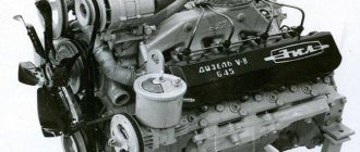
The correct approach to making non-standard decisions made the motors reliable, and the use of a number of technical techniques by the inventors made them recognizable. These characteristics include the operating order of KamAZ cylinders.
At first glance, the indicator is not significant. However, a detailed study of the issue brings clarity and understanding that the design of the installation is based on the order of operation of the KamAZ engine cylinders. Let's look at the characteristics in detail.
The operating order of Kamaz cylinders
/ Operating order of Kamaz cylinders
The main feature of the Kamaz 740 engine structure is the asymmetrical arrangement of the left row of pistons relative to the right one in such a way that the left piston group is extended 29.5 mm further. The fact is that there are two opposing connecting rods installed on the crankshaft journal, which determines the unique operating order of the Kamaz cylinders. The explosion sequence of the fuel mixture is the sequence 1→5→4→2→6→3→7→8.
Thanks to a shortened crankshaft with 8 pistons and 4 journals, the compression in the cylinders increased significantly, which in turn led to an increase in engine efficiency and power. The power in Kamaz 740 engines also increases due to the clearly tuned operation of the timing belt, including the valves.
What is the operating order of the Kamaz 740 cylinders?
According to the technical regulations of EU countries, the first cylinder in the Kamaz 740 engine is considered to be the one located in the right row at the front of the vehicle. This is usually called the master cylinder. The injectors have the same numbers as the cylinders on which they are installed. Therefore, the main injector corresponds to the master cylinder. Cylinder numbering starts from the right row, in which cylinders 1-4 are located. In the left row, cylinders 5-8 are respectively located. For both the right and left rows, the numbering starts from the front of the car.
| Knowledge of the operating order of Kamaz cylinders will be useful when debugging fuel injection after replacing the fuel pump, as well as when adjusting the timing belt, since the valves must open with a certain frequency and duration. Only in this case does smooth operation of the motor become possible. |
The special design of the Kamaz 740 engine makes it significantly smaller than Russian engines and more reliable than foreign ones. Kamaz 740 is ideal for working in the harsh conditions of the continental climate of our country, since it is quite easy to start in the cold season.
Specifications
As noted earlier, if such a pickup truck is put into production, it is more likely that it will be based on a platform from Mercedes-Benz. Moreover, the choice will fall on a front-wheel drive trolley, which will be borrowed from the compact GLB crossover. In this case, the Russian new product will receive a 1.33-liter supercharged engine that produces up to 150 hp. useful power. The type of gearbox still raises questions. Perhaps the manufacturer will leave the KamAZ-6520 2022 pickup truck with a continuously variable variator, which is used, in particular, on the Renault Arkana, equipped with the same turbo engine. The option with a 6-band automatic transmission is not excluded. The new pickup truck from KamAZ will not receive all-wheel drive.
Internal processes
The functioning of the KamAZ installation is associated with the processes occurring in the chamber. Actions occur in a certain strict sequence with periodic repetition in each cylinder. The sum of processes is a work cycle consisting of periods of gas distribution.
During one sequence of working processes, one ignition of fuel is performed in the cylinder. The delay period, from one flash to the next, affects the smooth running of the power unit. The smaller the gap, the less vibration when the motor operates. Smoothness also depends on how many cylinders there are in the KamAZ. In our version we are talking about eight cameras. This is a reasonable number, since a large number of cameras leads to a longer interval between flashes and harsh operation of the motor. At the same time, an insufficient number of cameras does not provide the necessary power.
Catalog of spare parts for KamAZ-6520 (Euro-4) (6520-3902009 KD):
Our catalog contains all spare parts used in KamAZ-6520 (Euro-4).
Select the node you need. To make it easier to find spare parts for KamAZ-6520 (Euro-4), you can use the quick filter. Quick Filter by nodes:
- Engine
Engine6520-1000261-41 Power unit, complete for installation on a vehicle
- 6520-1001000-60 Installation of power unit brackets
- 6520-1001005-60 Installation of the power unit
- 65115-1015265-10 Fuel tank
- 5320-1015384-10 Crane
- 6520-1080010-30 Lower hood of the engine compartment
- 4308-1009001 Installation of oil level indicator mounting parts
- 65201-1200004-34 Installation of the exhaust system
- 6520-1308005-90 Installation of a fan with a viscous coupling
- Transmission
Clutch
6520-1580004 Installation of soundproofing screen for gearbox
- 20.1600010-30 Clutch
- 5460-1600006-19 Installation of the pedal and clutch release drive
- 5460-1602008 Clutch pedal with bracket and master cylinder
- 6460-1602010 Clutch pedal
- 5320-1602510-10 Clutch master cylinder
- 5320-1602560 Clutch master cylinder reservoir
- 6520-1700005 Installing the gearbox on the engine
- 6520-2200001-75 Installation of cardan shafts
- 6520-2400015-10 Rear axle
- 6520-2500011-10 Middle bridge
- Frame, bumpers and engine mudguards
6520-2800010-58 Frame
- 6520-2900001-50 Installation of front suspension
- 6520-3000012 Front axle with brakes
- 65205-3101002 Installation of front wheels
- Steering
6520-3400002-19 Installation of the steering wheel
- 6520-3500006-01 Installation of pneumatic brake drive
- Electrical equipment
6520-3700011-56 Lighting equipment on a car
- 5308-3802001 Speedometer sealing
- 6520-4000012-30 ABS. Location by car
- Body
65201-5000007-10 Installation of cab suspension and cab lift limiter. Conventional assembly unit.
- 4308-5109001 Installation of carpets and floor thermal and noise insulation
- 6520-5205001 Installation of windshield wiper
- 6560-5300023-10 Installation of the instrument panel
- 65115-5603005 Installation of rear window glass
- 65115-6100005 Installation of glass and door fittings
- 54115-6800900-02 Connection diagram for seat pneumatic system
- 4308-7900010 Radio equipment. Location on the instrument panel
- 4308-8100005 Installation of cabin heating system
- 6520-8212008-01 Installation of factory side signs
- 43255-8400006 Installation of cockpit tail
Spare parts diagrams and components are presented on the website for reference purposes! We do not sell all spare parts for KamAZ-6520 (Euro-4) presented in this list, but many of them.
Kamaz engine
The engine consists of crank and gas distribution mechanisms, as well as cooling, lubrication, power and control systems, and starting. With the help of a crank mechanism, the reciprocating movement of the pistons in the cylinders is converted into rotational movement of the crankshaft.
Rice. 1.1. Engine KamAZ-740.10 (basic model): a - longitudinal section, b - cross section; 1 - generator, 2 - low-pressure fuel pump, 3 - manual fuel pump, 4 - high-pressure fuel pump, 5 - automatic fuel injection advance clutch, 6 - drive coupling half of the high-pressure fuel pump drive, 7 - connecting pipe of the intake air ducts, 8 — fine fuel filter, 9 — camshaft, 10 — flywheel, 11 — flywheel housing, 12 — drain plug; 13 — oil pan, 14 — crankshaft, 15 — oil pump, 16 — fluid coupling drive shaft, 17 — generator drive pulley; 18 — fan blades, 19 — full-flow oil filter, 20 — oil filler neck, oil level indicator in the engine crankcase, 22 — centrifugal oil filter, 23 — transmission gearbox, 24 — front eye bolt, 25 — compressor, 26 — power steering pump at, 27 — rear eye bolt, 28 — left drainage pipe, 29 — flare plug, 30 — left air inlet pipe, 31 — injector, 32 — injector mounting bracket 33 — exhaust manifold pipe, 34 — exhaust manifold
The gas distribution mechanism promptly opens and closes the valves, which allow air into the cylinders and exhaust gases out of the cylinders.
The cooling system maintains the required thermal conditions of the engine.
The lubrication system supplies oil to the rubbing parts of the engine to reduce friction and wear.
The power system cleans and supplies air and fuel to the cylinders, and with the help of a regulator, it automatically regulates the flow (supply) of fuel into the combustion chamber depending on the engine load.
The diesel starting system is necessary to turn the crankshaft during startup.
Here we will describe a set of components of the KamAZ-740.10, KamAZ-7403.10 and KamAZ-7409.10 engines, explain the operating diagram and operating principle of their mechanisms and systems. The KamAZ-740.10 engine (Fig. 1) is a four-stroke liquid-cooled diesel engine with a V-shaped arrangement of eight cylinders; is the base for all engine modifications of the brand. The KamA3 engine - 7403.10 (Fig. 2) has increased power due to the use of gas turbine supercharging, in which part of the energy of the exhaust gases is used to compress air and force it into the cylinders. Gas diesel engine 7409.10 (Fig. 3) can operate both on natural gas with its ignition by a pilot dose of diesel fuel, and on diesel fuel in diesel mode.
Rice. 3. General view of the K.AMAZ-7403.10 turbocharged engine: 1 - connecting pipe, 2 - high-pressure fuel pump model 334, 3, air ducts, 4.7 - turbochargers, 6 - pipe, 8 - exhaust manifold, model 271 5 - inlet 9 - nozzle
Rice. 4. General view of the KamAZ-7409.10 engine (gas diesel): 1 - connecting pipe. 2, 10 — intake air ducts, 3 — high-pressure fuel pump model 335, 4 — individual compressor air cleaner, 5 — low-pressure reducer. 6 - solenoid valve with filter, 7 - control drive with gas dispenser, 8 - gas dispenser. 9 - mixer, 11 - speed control drive
The main design data and parameters of the engines are given in the technical specifications (the values are given in parentheses when the engine is operating in diesel mode).
Technical characteristics of KamAZ engines
| Model | 740.10 | 7403.10 | 7409.10 |
| Number of cycles | 4 | ||
| Number of cylinders | 8 | ||
| Cylinder arrangement | V-shaped, camber angle 90° | ||
| Cylinder operating order | 1—5—4—2—6—3—7—8 | ||
| Crankshaft rotation direction | right | ||
| Cylinder diameter and piston stroke, mm | 120 X 120 | ||
| Working volume, l | 10,85 | ||
| Compression ratio | 17 | 16 | 17 |
| Rated power, kW | 154 | 191 | 154 |
| Maximum torque, Nm | 637 | 785 | 637 |
| Crankshaft rotation speed, rpm: | |||
| nominal | 2600 | 2600 | 2550 (2600) |
| at maximum torque | |||
| 1600…1800 | 1600… 1800 | 1300… 1800 |
Not available:
| № | Part code | Name | Part Information |
| 740-51-1000400-20 | Engine 740.51-320 with equipment | Quantity per 6520 1 Model 740.51 Group Engine Subgroup Engine assembly Serial part number 400 Additionally Not interchangeable with a part previously released under the same number | Not available |
| 740-20-3407001 | Installing the power steering pump | Quantity per 6520 1 Model 740.20 Group Steering control Subgroup Power steering pump Part number 001 | Not available |
| 7406-3509003-10 | Compressor installation | Quantity per 6520 1 Model 7406 Group Brakes Subgroup Air brake compressor Serial part number 003 Additionally Not interchangeable with a part previously released under the same number | Not available |
| 5662-3708-10 | Starter | Quantity per 6520 1 | Not available |
| 7406-3701011 | Generator | Quantity per 6520 1 Model 7406 Group Electrical equipment Subgroup Generator Part serial number 011 | Not available |
| 740-20-1307170 | Alternator and water pump drive belt | Quantity per 6520 1 Model 740.20 Group Cooling system Subgroup Water pump Part number 170 | Not available |
