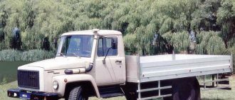
Scheme GAZ 3309 diesel
Scheme GAZ 3309 diesel four-stroke, turbocharged, liquid-cooled, with a displacement of 4.75 liters and a power of 147 hp. The diesel engine is equipped with a high-pressure fuel pump with a booster pump.
Scheme GAZ 3309 diesel D245
Scheme GAZ 3309 Diesel D-245 is a 4-stroke piston four-cylinder internal combustion engine with an in-line vertical cylinder arrangement, direct injection of diesel fuel and compression ignition.
The main elements of the GAZ 3309 diesel engine are: cylinder block, cylinder head, pistons, connecting rods, crankshaft and flywheel.
To ensure high technical and economic indicators of the diesel engine, turbocharging with intermediate cooling of the charge air is used in the intake system.
The use of a turbocharger with adjustable boost pressure in the supercharging device allows for improved throttle response on a diesel engine, provided by increased torque values at low crankshaft speeds.
brake system diagram gas 3309
Description of the book
Repair book for GAZ 3308
Operation of any GAZ 3308 vehicle is impossible without knowledge of its structure, maintenance and repair features. It doesn’t matter who will carry out the necessary work - every driver is simply obliged to know the basic maintenance and troubleshooting procedures.
The GAZ 3308 repair book contains all the necessary information that will help the owner understand the structure of the car, teach how to properly care for the car, timely maintenance and proper repairs.
The GAZ 3308 repair manual is divided into chapters: Vehicle design (describes general information and vehicle specifications); Operating instructions (preparation for departure, recommendations for traffic safety); Malfunctions along the way (tips to help you in case of an unexpected breakdown on the road); Maintenance (detailed recommendations for all maintenance procedures); Repair instructions (engine, transmission, chassis, steering, brake system, and also includes assembly and disassembly work necessary during the repair process of the GAZ 3308); Electrical equipment (detailed manual for diagnosing and troubleshooting, the main units are described separately and detailed electrical diagrams of the GAZ 3308 are given).
Any of the GAZ 3308 repair procedures is given according to the principle from simple to complex: from simple maintenance operations, adjustments, replacement of parts, to global repairs with assembly and disassembly work.
All materials in the book are based on specific experience gained in the process of complete disassembly and assembly of the GAZ 3308 by highly qualified auto mechanics.
The book “GAZ-3308, 33081. Maintenance, operation, repair, electrical circuits” is necessary so that diagnostics and repairs of the GAZ 3308 can be done professionally and quickly, even by the owner of the car who still has little practical experience.
You can download the GAZ 3308 repair manual for free in pdf format. You just need to download it to your phone or tablet and you can use it in any situation on the road.
GAZ 3309 gearbox diagram
GAZ 3309 gearbox diagram
GAZ 3309 gearbox diagram : 1 - front crankcase; 2 — adjusting shims; 3 - intermediate shaft; 4,5,44 — intermediate shaft gears; 8.31 - cuffs; 7 — input shaft cover; 8 - input shaft; 9 — roller bearing; 10 — bearing washer; 11 — synchronizer for fourth and fifth gears; 12 — removable crown of the input shaft; 13 — synchronizer blocking ring; 14.32 - plugs; 15,25,28 — gear forks; 16 — retainer balls; 17 — lever housing gasket; 18 — gear shift lever; 19 — lever cap; 20 — lever seal; 21 - lever cap gasket; 22 — lever housing; 23 — removable crown of gears of the second and third gears; 24 — fork mounting bolt; 26 — synchronizer for second and third gears; 27 - secondary shaft; 29 — rear housing; 30 — speedometer drive gear; Diagram of the GAZ 3309 gearbox. 33 - flange nut; 34 — secondary shaft flange; 35.40, 41.45, 46 - secondary shaft gears; 36 — hub of the clutch for engaging first gear and reverse gear; 37 — clutch; 38 — removable crown of gears of first gear and reverse gear; 39 — intermediate shaft bearing; 42 — needle bearing of the secondary shaft gears; 43 - drain plug
GAZ 3309 electrical diagram
Electrical diagram of GAZ 3309 - direct current, single-wire. The negative terminals of power supplies and consumers are connected to the housing. Rated voltage 24V.
Symbols for the elements of the electrical circuit of GAZ 3309 : AB - pre-heater; A10 - heater; B1 - oil pressure indicator sensor; B2 - sensor for emergency oil pressure drop alarm; B7 — coolant temperature indicator sensor; B8 - coolant overheat indicator sensor; B12 - fuel indicator sensor; B19 - air filter clogging warning sensor; B31 - emergency pressure sensor; B32 — emergency pressure sensor (II brake circuit); B61 — preheater overheating indicator sensor; B67 - brake fluid sensor; B97 — pressure sensor (I brake circuit); B96 - pressure sensor; B99 - emergency piston stroke sensor in the pneumatic booster (I brake circuit); B100 — emergency piston stroke sensor in the left pneumatic booster (II brake area); B101 — emergency piston stroke sensor in the pneumatic booster, right (II brake circuit); D25 — control unit for electric headlight corrector; E1 — left headlight; E2 — right headlight; E5 — front left lamp; E6 — front right lamp; E9 — left turn signal repeater; E10 — right turn signal repeater; E11 — front left contour lamp; E12 — front right contour lamp; E16 — cabin ceiling; E27 — rear left lamp; E28 — rear right lamp; E29 - reversing lamp; E31 - rear fog lamp; E33 — rear left contour lamp; E34 — rear right contour lamp; E35 - engine compartment light; E37 — front left side marker lamp; E38 — front right side marker lamp; E39 — rear left side marker lamp; E40 — rear right side marker lamp; E50U53 - glow plugs; E54 - glow plug for pre-heater; E73 - left signaling unit; E84 - right signaling unit; F26 - thermal fuse for pre-heater; F41 - fuse block; F42 - upper fuse box; F43 - lower fuse box; G1 - generator; G2G5 - rechargeable batteries; Н1 — left sound signal; H2 - right sound signal; H3 — air pressure drop buzzer; H7 - alarm indicator for emergency drop in oil pressure; H8 - coolant overheat indicator; H9 - pre-heater overheating indicator; H11 - air filter clogging indicator; H16 - turn signal indicator; H19 - critical fuel level indicator; H20 - high beam headlight indicator; H30 - parking brake activation indicator; H37 - pre-heater operation indicator; H39 - ABS fault indicator; H44 - backlight lamp for air pressure level indicator; H45 — backlight lamp for air pressure level indicator; H47 - fuel indicator illumination lamp.
Electrical diagram of GAZ 3309
Symbols for the elements of the electrical circuit of GAZ 3309 : AB - pre-heater; A10 - heater; B1 - oil pressure indicator sensor; B2 - sensor for emergency oil pressure drop alarm; B7 — coolant temperature indicator sensor; B8 - coolant overheat indicator sensor; B12 - fuel indicator sensor; B19 - air filter clogging warning sensor; B31 - emergency pressure sensor; B32 — emergency pressure sensor (II brake circuit); B61 — preheater overheating indicator sensor; B67 - brake fluid sensor; B97 — pressure sensor (I brake circuit); B96 - pressure sensor; B99 - emergency piston stroke sensor in the pneumatic booster (I brake circuit); B100 — emergency piston stroke sensor in the left pneumatic booster (II brake area); B101 — emergency piston stroke sensor in the pneumatic booster, right (II brake circuit); D25 — control unit for electric headlight corrector; E1 — left headlight; E2 — right headlight; E5 — front left lamp; E6 — front right lamp; E9 — left turn signal repeater; E10 — right turn signal repeater; E11 — front left contour lamp; E12 — front right contour lamp; E16 — cabin ceiling; E27 — rear left lamp; E28 — rear right lamp; E29 - reversing lamp; E31 - rear fog lamp; E33 — rear left contour lamp; E34 — rear right contour lamp; E35 - engine compartment light; E37 — front left side marker lamp; E38 — front right side marker lamp; E39 — rear left side marker lamp; E40 — rear right side marker lamp; E50U53 - glow plugs; E54 - glow plug for pre-heater; E73 - left signaling unit; E84 - right signaling unit; F26 - thermal fuse for pre-heater; F41 - fuse block; F42 - upper fuse box; F43 - lower fuse box; G1 - generator; G2G5 - rechargeable batteries; Н1 — left sound signal; H2 - right sound signal; H3 — air pressure drop buzzer; H7 - alarm indicator for emergency drop in oil pressure; H8 - coolant overheat indicator; H9 - pre-heater overheating indicator; H11 - air filter clogging indicator; H16 - turn signal indicator; H19 - critical fuel level indicator; H20 - high beam headlight indicator; H30 - parking brake activation indicator; H37 - pre-heater operation indicator; H39 - ABS fault indicator; H44 - backlight lamp for air pressure level indicator; H45 — backlight lamp for air pressure level indicator; H47 - fuel indicator illumination lamp.
GAZ 3309 electrical circuit diagram
Designation on the ABS circuit of the GAZ 3309 car : B87 - front left wheel speed sensor; B88 — front right wheel speed sensor; B89 - rotation speed sensor of the left wheel; B90 — rotation speed sensor of the right wheel; D7 - ABS control unit; E89 - ABS air dryer; F54 - ABS fuse block; K73 - ABS air dryer relay; S139 - ABS diagnostic switch; X41 - pin block; Ch55 — diagnostic block; Y56 — front ABS modulator; Y57 - rear left ABS modulator; Y58 - rear right ABS modulator.
How does an electromagnetic-thermal relay work?
These devices are no longer used in modern cars. However, in older models they are still widely used.
The design of the electromagnetic-thermal relay is quite simple; it uses a circuit for connecting turn signals through an electromagnetic-type relay. It is made in the form of a cylindrical core, and a thin copper wire is used as its winding. At the top of the core there are two groups of contacts, and metal anchors are installed on each side. The first group of contacts closes the circuit where there is a control light located on the instrument panel. With the help of other contacts, the circuit with the lamps in the direction indicators is closed. They are the ones who provide the flashing mode.
A thin nichrome string is attached to the anchor of the main group of contacts. It pulls the armature away from the contact, which is located on the core. Thus, the circuit will be open, which is its normal position. The core itself is installed on a special insulated platform, where the opposite end of the string is also fastened. During operation, an electric current passes through the string, since it, together with the resistor, is in the switch circuit. All elements of the device are housed in a cylindrical metal case.
The operating principle of an electromagnetic-thermal relay is very simple. When the turn signal is turned on, the circuit is completed. Under the influence of current, the nichrome string heats up and its length increases. The anchor, which was previously pulled back, is attracted by the core, straightens and closes the contacts for a short time. Because of this, the turn signal lamps begin to shine at full intensity. The current passes by the string, causing it to cool and shorten again. As a result, the armature is pulled away from the core, which leads to the opening of the contacts. The lamps stop shining, then the whole cycle resumes. The nichrome string heats up and cools down very quickly, ensuring that the lamps blink at an average frequency of 60-120 times per minute.
The blinking of the light located on the panel is also associated with the operation of the main group of contacts. Therefore it works synchronously with the warning lamps. Mini-audio signals in the form of characteristic clicks appear when the armature and contacts close and open, hitting each other.
A significant disadvantage of this device is the gradual stretching of the string, which disrupts the normal operation of the relay. Therefore, these devices are now being replaced by more modern electronic relay designs.
Wiring diagram GAZ 3309
Wiring diagram for GAZ 3309 : 1 - left side turn signal; 2 — left headlight; 3 — right headlight; 4 — right side indicator; 5 - starter; 6 — fuse box (in the engine compartment); 7 — headlight relay; 8 - central lighting switch; 9.10 — lampshades for lighting the cargo compartment of GAZ 3309; 11 — courtesy lamp for the front part of the GAZ 3309 cab; 12 — windshield washer motor; 13 — canopy lighting for the rear part of the cabin with two rows of seats GAZ 3309; 14 — switch for the rear part of the cabin lighting; 15 — lampshade of the GAZ 3309 platform; 16 — buzzer switch; 17 — driver signal buzzer; 18 — sound signals; 19 — sound signal relay; 20 — ignition switch; 21 — starter relay; 22 - generator; 23 - battery; 24 — battery switch; 25 — remote battery switch button; 26 — electric heater drive; 27 — electric pump for additional heater; 28 — heater electric fan resistor; 29 — the fan electric motor is heated; 30 — heating and ventilation control panel; 31 — upper fuse block; 32 — lower fuse block; 33 — engine compartment lamp; 34 — hazard light switch; 35 — radio receiver; 36 — resistor of the additional heater electric motor; 37 — additional heater electric motor; 38 — switch for interior lamps; 39 — interior lamp switch (left side); 40 — lamp of the running board; 41 — interior lamps (right side); 42 — interior lamp of GAZ 3309 (left side); 43 — cigarette lighter; Electrical wiring diagram GAZ 3309; 44 — switch for checking the serviceability of signaling devices; 45 — sensor for emergency drop in brake fluid level; 46 — right steering column switch; 47 — turn signal relay; 48 — switch for electric headlight correctors; 49 — parking brake warning switch; 50 — parking brake warning relay; 51 — lighting control of the instrument cluster; 52 - times for connecting the ABS system of GAZ 3309; 53 — instrument cluster; 54 — brake signal switch; 55 — switch for the glove compartment lamp; 56 — lampshade lighting of the glove box; 57 — fuel module; 58 — switch for the GAZ 3309 center differential lock indicator; 59 — windshield wiper control relay; 60 — block of the GAZ 3309 engine control system; 61 — coolant temperature indicator sensor; 62 — coolant overheat warning sensor; 63 — windshield wiper; 64 — oil pressure indicator sensor; 65 — emergency oil pressure indicator sensor; 66 — right steering column switch; 67 — speed sensor GAZ 3309; 68 — reverse light switch; 69 — rear light; 70 — license plate lights; 71 — rear light (left)
Blocks under the hood
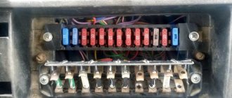
Fuse box
Spare fuses are located in the fuse box cover.
Option 1
A fuse block of four fuses for 60A, 30A, 60A and 30A is installed on the power steering reservoir mounting bracket.
p, blockquote 21,0,0,0,0 —>
The 60A extreme fuse protects the glow plug pin circuit. A 30A fuse protects the vehicle's light circuit. The second 60A fuse protects all vehicle circuits except the starter circuit. A 30A extreme fuse protects the engine control unit circuit.
p, blockquote 22,0,0,0,0 —>
Option 2
On the right side of the hood side panel there is a fuse block of four fuses for 30A, 40A, 90A and 125A.
p, blockquote 23,0,0,0,0 —>
A 30A fuse protects the engine control unit circuit. A 40A fuse protects the vehicle's light circuit. A 90A fuse protects the vehicle's common positive circuit. A 125A fuse protects the air heater circuit.
p, blockquote 24,0,0,0,0 —>
Relay block
It is mounted on a special reader and here the engine control relay and spark plugs can be located.
p, blockquote 25,0,0,0,0 —>
p, blockquote 26,0,0,0,0 —> p, blockquote 27,0,0,0,1 —>
That's all. And if you want to help supplement the material, then write in the comments.
GAZ 3309 steering diagram
The steering diagram of the GAZ-3309 is a steering mechanism with a 3-joint steering column with a splineless connection, which ensures a change in the length of the propeller shaft of the column when the cab oscillates.
GAZ 3309 steering diagram
Steering diagram : 1 - crankcase; 2 - screw with ball nut; 3 - shaft sector; 4 — filler plug; 5 — adjusting shims; 6 - nut; 7 - bolt; 8 - fork; 9 - cover; 10 - wedge; 11 - intermediate support; 12 — middle cardan shaft; 13 — upper casing; 14 — steering wheel; 15 - overlay; 16 - lower casing; 17 - column; 18 — steering lock; 19 — side cover; 20 — lock washer; 21 — adjusting nut; 22 - spacer; 23 , 28 - sealing rings; 24 - plug; 25 - cover; 26 — seal; 27 — bipod; 29 — protective ring; 30 — outer ring of the sector shaft bearing; 31 — retaining ring; 32 - cardan shaft.
GAZ 3309
Modifications and homemade products based on the car
After the modernization of the GAZ-66, modifications with specialized bodies became widespread in the national economy. The following machines stand out in particular:
- sewer truck ANM-53;
- fire installations ATs-20, 30;
- ambulance tow truck AS-66;
- auto-dressing AP-2;
- oil tanker MZ-66;
- isotherm van GAZ-2766.
Many craftsmen are able to remake equipment using the chassis of a military vehicle. For example, on domestic roads you can find an SUV converted into a Jeep.
Dump truck
A representative of the equipment is the GAZ-SAZ-3511 - an all-wheel drive dump truck based on the 6631 modification with a PTO, double rear axle tires and a diesel engine with a long service life of up to 150 thousand km. There is no centralized tire inflation mechanism. A dump body with a volume of 5 m³ unloads bulk construction and agricultural materials in 3 directions. By installing additional sides, the capacity is doubled. The lifting mechanism is hydraulic.
KUNG
The KUNG is a closed-type frame-metal template van body made of steel channels and angles. The structure is sheathed on the outside with aluminum sheets and sealed inside with plywood treated with varnish.
Internal components of KUNG:
- heating and ventilation system;
- filter and ventilation unit;
- lighting;
- household equipment;
- sleeping places.
An example of a model with a sealed van is modification 6611.
Firefighter
In total, there are 9 versions of fire engines on the 66th model chassis. The most common is the AC-30 tank truck based on 6601. The specialized equipment includes:
- water tank coated with epoxy enamel, capacity 1500 l;
- fire pump PN-40 with a manifold and foam mixer;
- sleeves with a diameter of 51 and 66 mm;
- trunk;
- ladder.
Fire-technical weapons are used to extinguish fires and carry out emergency rescue operations both in urban areas and in off-road conditions.
Drilling rig
The UGB-50 drilling rig based on the 66th truck is designed for horizontal drilling of hydrogeological wells for the purpose of studying soil, searching for mineral deposits, and water intake. Geological exploration is carried out by core sampling using the shock-rope method. The drilling depth of the auger reaches 100 m.
Manipulator
The body of the manipulator is a metal platform with high side sides and an opening rear one. A crane-manipulator is mounted at the front of the upper part of the chassis, which is used to move, lift and transport goods.
The best option for GAZ is Japanese equipment Tadano-Z290 with a minimum reach of a 3-section boom of 2.95 m, a radius of 8 m. The mechanism is capable of lifting a load weighing up to 4 tons.
GAZ 3309 steering wheel diagram
The GAZ-3309 car is equipped with a separate power steering (power steering). Below is a detailed diagram of the power steering GAZ 3309.
Power steering diagram GAZ 3309
Power steering diagram GAZ 3309: 1 - bipod; 2 — discharge hose; 3 — drain hose; 4 — spar; 5 — grease nipple; 6 — front axle beam; 7 - clamp; 8 — longitudinal steering rod; 9 , 14 - fingers; 10 , 11 — hoses of the power cylinder; 12 — transverse steering rod; 13 - cylinder seal; 15 — power cylinder; 16 — connecting bracket.
Installation diagram of the power steering pump GAZ 3309
Installation diagram of the power steering pump : 1 - power steering pump; 2 — discharge tube; 3 - suction tube; 4 - valve box.
Types and design features of vacuum pumps GAZ-3306
On GAZ-3306/33081/3309 vehicles, only one type and model of vacuum pump is currently used - a “wet” rotary (vane) pump model 33081-3548010-01.
The design of the pump is extremely simple. Its basis is a cylindrical body with a conical front part; on the wall of the body there is a pipe for connection to the vacuum circuit of the brake system. A cylindrical rotor with four radial grooves into which blades (vanes) are freely inserted is asymmetrically installed inside the housing. The rotor is mounted on a shaft that extends through the front of the housing and ends at a drive pulley. The roller rests on two bearings, the gap between the roller and the body is sealed with a cuff. At the rear, the pump is closed with a bolted cover, which contains fittings for connecting the inlet and outlet oil hoses (they are connected to the corresponding fittings on the engine and oil filter).
There are eyes on the pump body, with the help of which the unit is installed on the engine and its position is adjusted (for normal belt tension). The pump is driven by a V-belt drive from a fan pulley, which also rotates the generator and water pump. The drive of these units is realized by two parallel belts, however, a single pulley is installed on the pump, so when installing it, the outer belt is replaced with a longer one, it is thrown over the pump pulley and ensures its rotation.
Generator circuit GAZ 3309
Generator circuit 5101.3701 GAZ 3309 with diodes and voltage regulator YA120M1. Old style diode bridge BPV 56-65-02 with two wires. The GAZ 3309 generator consists of a housing, stator winding, rotor, diode bridge and built-in voltage regulator.
Generator circuit GAZ 3309
The GAZ 3309 generator circuit, thanks to a system with additional diodes, allows you to receive current from the output of additional diodes, and not from the generator output as before. Thanks to this scheme, battery discharge through the generator excitation winding is practically reduced to zero. The current in a similar circuit of the GAZ 3309 generator flows only inside the generator itself, without using external circuits and the ignition switch (except for the initial excitation).
Troubleshooting
If any device fails, using an electrical circuit it is easy to check whether it has failed or whether the electrical circuit has been interrupted somewhere.
Power supply circuit for a GZ-3307 car. To do this, you will need a test light with wires and clamps or a tester turned on in voltmeter mode (voltage detection). We connect one clamp of the light bulb (tester) to the input contact of the element being tested, the other to the “ground”, that is, the negative terminal of the battery or any part of the frame, body or engine (cleaned of paint).
Color scheme GAZ 3309
The GAZ 3309 color diagram allows you to quickly and clearly read the electrical wiring diagram of the GAZ 3309 car.
Color scheme GAZ 3309
- Side turn signal mounted on the right front fender.
- Front marker light (right).
- Right headlight.
- Connection strip.
- Left headlight.
- Low beam lamp installed in the headlight.
- High beam lamp.
- Side light bulb.
- Front marker light (left).
- Direction indicator lamp installed in the front position lamp.
- Side turn signal located on the left front fender.
- Coil.
- Spark pulse distributor.
- Candle.
- An additional resistor to eliminate radio interference in the spark plug tip.
- Starter.
- Battery.
- Starter control relay.
- Battery power switch.
- Indicator lamp for activated high beam headlights.
- Upper section of the interior fuse box.
- Klaxon.
- Gas valve solenoid. Installed only on trucks equipped with gas cylinder equipment.
- Electromagnetic element of the gasoline supply valve, used on vehicles with a combined fuel system (gas-gasoline).
- Fuel type switch.
- Ignition system switch.
- An auxiliary relay that turns on the starter.
- Central lighting mode switch.
- Generator.
- Control key for rear fog lamp operation.
- Plug connector.
- Control resistance.
- Additional fuse for autonomous heater. The unit is installed as a separate order.
- An electric motor that ensures the functioning of an independent engine heating system.
- Instrument cluster illumination lamp.
- Cabin lighting.
- Ammeter.
- Voltage regulator unit in the on-board network.
- Autonomous heater control panel.
- Fuel ignition switch in the heater boiler.
- Autonomous operating mode switch.
- An electromagnetic valve that regulates the supply of gasoline to the combustion chamber of an autonomous heater.
- Gas system pressure gauge.
- Coolant temperature sensor.
- Sensor for turning on a lamp warning of overheating of the power plant.
- A sensor that transmits information about the pressure in the lubrication system.
- A separate device that measures critically low pressure in oil lines.
- Ignition switch with built-in contact group.
- Bottom of the interior fuse box.
- A socket designed to connect additional equipment (portable lamp, etc.).
- Alarm control button.
- Starter heater spark plug.
- Second gas system pressure gauge.
- Gasoline level indicator in the fuel tank.
- A control device that displays engine temperature.
- Lubrication system pressure gauge.
- Electric motor to drive the windshield wiper blades.
- Control relay for the glass cleaning system.
- Washer pump drive motor.
- The steering column switch is responsible for selecting the operating modes of the headlights and direction indicators.
- An additional device is used to provide warning sounds.
- Key for turning on increased fan speed for the standard cabin heating system.
- A similar unit for lower frequency.
- Brake light limit switch.
- Toggle switch for determining the fuel level in different tanks.
- Steering column switch for windshield wiper operating modes.
- A separate indicator displaying the operation of turn signals on towed equipment.
- Indicator lamp for direction indicators on the tractor. When using a single vehicle, only this lamp is active.
- Indicator for turning on side lighting.
- Indicator of the state of the drive of the second circuit of the brake system.
- A similar lamp for the first circuit.
- Indicator lamp for activation of the parking brake and malfunctions in the main circuits.
- Signal unit housing.
- Limit switch for determining the position of the parking brake handle.
- Heater motor on the right side of the cab.
- A similar unit for the left side.
- Measuring fluid level sensor in the hydraulic brake drive.
- A sensor that measures the degree of vacuum in the first brake circuit.
- A similar device for the second circuit.
- Sensor for measuring the amount of fuel in the main tank.
- Switch plate.
- Limit switch in the crankcase box, used to connect the reverse light.
- A contact relay that provides operation of the hazard warning lights and direction indicators.
- Fuel level measurement sensor in the additional tank.
- Back light.
- Socket for connecting electrical equipment on the trailer.
- Fog light mounted on the rear of the truck.
- Reverse lamp.
- Brake warning lamp.
- Dimensional signal.
- Rear direction indicator.
Description
The electrical circuit of the GAZ-3307 is a drawing on which there are pictograms of the electrical elements of the car, connected to each other by switching lines indicating wires. The equipment is located approximately where it is when looking at the machine from above, although deviations (sometimes significant) are possible. On the left are usually the headlights and sidelights of the front of the car, to the right are the electrical equipment of the engine compartment, interior and rear lights.
Electrical circuits are available in black and white and color. The latter are easier to read; the colors of the lines are the same as those of the corresponding wires. Often electrical components are shown in the form of pictures (instrument panel, starter, headlights, etc.), they can be recognized without looking at the “legend” (the explanatory text under the diagram or on the side of it). An example of a color wiring diagram is shown below.
Black and white diagrams are usually more detailed and often provide additional information (for example, thin lines show current conductors inside devices). The color of the wires is indicated by a letter (H - black, Z - green, and so on). The numbers (2; 0.5 and others) in the breaks in the switching lines indicate the cross-sectional area of the wire in square millimeters. There are standard pictograms and conventional images of certain devices. Next to them (sometimes on a callout) is a number or letter with numbers. This is the designation of the element whose name is indicated in the “legend”.
ABS diagram GAZ 3309
The ABS scheme of the GAZ 3309 is an ABS anti-lock braking system that provides effective braking and a minimum braking distance, preventing blocking of wheels located in less favorable traction conditions on ice.
GAZ 3309
The GAZ 3309 ABS diagram consists of four ABS sensors in the wheel units of the car, three modulators on pneumatic amplifiers, an ABS control unit, an ABS diagnostic button, an ABS fault indicator and an ABS harness connecting the sensors and modulators of the control unit on the GAZ 3309 ABS diagram.
ABS diagram GAZ 3309
ABS diagram GAZ 3309: 1 compressor; 2 – air dryer with pneumatic regulator; 3 – regeneration air cylinder; 4 – double-circuit protective valve; 5 – air pressure drop sensor; 6 – air cylinder; 7 – condensate drain valve; 8 – two-section brake valve with lever; 9 – ABS rotor speed sensor; 10 – brake mechanism with ABS rotor on the hub; 11 – electric pressure gauge; 12 — buzzer; 13 – indicator of emergency piston movement and drop in brake fluid level; 14 – ABS signaling device; 15 – two-section tank; 16 – pneumatic booster with main cylinder; 17 filter; 18 – emergency piston stroke sensor; 19 – control valve; 20 – ABS modulator; 21 – ABS control unit; 22 – sensor for switching on the “STOP” signal; 23 – pressure gauge sensor; 24 – “STOP” signal lamp; 25 – brake fluid level drop sensor; 26 – silencer
DIY turn relay
Sometimes situations arise when the standard turn signal relay fails and it is not possible to purchase a new device. In such a situation, you can try to make a turn signal relay with your own hands to provide the car with the necessary signals. The simplest electronic devices that you can create yourself are simple and easy to use, operate smoothly and reliably. High accuracy is achieved through the use of PWM controllers used in all circuits.
The simplest replacement for an electromagnetic relay is designed for a maximum load power of 150 W. It is connected to the positive terminal. If the IRFZ44 field switch is replaced with the IRF3205 model, then 200 W can be connected. This simple circuit ensures high accuracy of operation. The blinking frequency does not depend on the power of the light bulbs, so LED, halogen and other lamps can be included in the circuit.
The frequency of flashing is directly related to the capacitance of the capacitor. As the capacity increases, the light bulb will blink more rarely, and, conversely, decreasing the capacity will lead to faster blinking. The low-power 1n4148 diode can be replaced by any similar element. When the circuit reaches a power of 80 W, a slight generation of heat is observed in the field-effect transistor area. This means it is ready to use.
There is another simple circuit of a turn relay with a coil - simple, reliable and inexpensive. It is capable of lighting both regular light bulbs and LED ones and is designed for 12 V. The contacts are connected according to the principle of a regular switch, that is, in series with the light bulb. The LED is installed in the circuit as an indicator during commissioning work. The device parameters are adjusted by changing the resistance of the resistor.
GAZ 3309 fuel system diagram
The diagram of the fuel system of GAZ-3309, GAZ-3308, GAZ-33081 Sadko consists of a fuel pump, injectors, low and high pressure fuel lines, an air cleaner, intake and exhaust manifolds, coarse and fine fuel filters, as well as a fuel tank.
GAZ 3309 fuel system diagram
GAZ 3309 fuel system diagram : 1 - fuel tank; 2 – fuel coarse filter; 3 — low pressure fuel pipes; 4 – high pressure fuel pump; 5 – fuel priming pump; 6 – high pressure fuel pipes; 7 — fine fuel filter (non-separable); 8 – air cleaner; 9 — fine fuel filter (with a replaceable filter element); 10 – glow plug; 11 – intake manifold; 12 – exhaust manifold; 13 – muffler; 14 – nozzle; 15 – fuel drain pipe into the tank; 16 — cylinder head; 17 – turbocharger; 18 – pneumatic corrector tube; 19 – charge air cooler.
Blocks under the hood
Fuse box
Spare fuses are located in the fuse box cover.
Option 1
A fuse block of four fuses for 60A, 30A, 60A and 30A is installed on the power steering reservoir mounting bracket.
p, blockquote 21,0,0,0,0 —>
The 60A extreme fuse protects the glow plug pin circuit. A 30A fuse protects the vehicle's light circuit. The second 60A fuse protects all vehicle circuits except the starter circuit. A 30A extreme fuse protects the engine control unit circuit.
p, blockquote 22,0,0,0,0 —>
Scheme of autonomous cabin heater GAZ 3309
The circuit diagram of an autonomous heater for a GAZ 3309 cab consists of an air intake, a heater radiator, two fans and a coolant. The autonomous heater maintains the specified temperature conditions in the GAZ 3309 cabin, as well as for blowing the windshield and door windows.
Scheme of autonomous cabin heater GAZ 3309
Diagram of the autonomous cabin heater GAZ 3309:
- 1 and 7 – nozzles for heated side windows
- 2 and 6 – windshield heating pipes
- 3 – air intake box
- 4 – air intake duct damper
- 5 – heater radiator
- 8 and 12 distributors
- 9 – radiator casing
- 10 damper
- 11 lever arm
- 13 cladding
- 14 – air intake damper control handle
- 15 – heater tap control handle