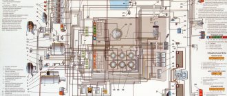
The diagrams are presented as information and reference material for servicing the electrical equipment of MAZ vehicles. The diagrams are general in nature and may differ from the connection on a real car depending on the specific configuration.
| Electrical diagrams for MAZ vehicles of the 4370 family: | Electrical circuit diagram for a MAZ-437030 car with a Deutz engine |
| Electrical circuit diagram for a MAZ-437043 car with an MMZ engine | |
| Electrical diagrams for MAZ vehicles of the 4371 family: | Electrical circuit diagram for a MAZ-4371P2 car with an MMZ E4 engine |
| Electrical diagrams for MAZ cars of the 5440 family: | Electrical diagrams for MAZ cars of the 5440 family (harnesses) |
| Electrical diagrams for MAZ cars of the 5440 family (diagram) | |
| Electrical diagrams for MAZ vehicles of the 6422 family: | Electrical circuit diagram for the MAZ-533605 car |
| Electrical circuit diagram for the MAZ-543205 car | |
| Electrical circuit diagram for the MAZ-551605 car | |
| Electrical circuit diagram for the MAZ-555102 car | |
| Electrical circuit diagram for the MAZ-630305 car | |
| Electrical circuit diagram for the MAZ-642205 car | |
| List of elements for circuit diagrams | |
| Electrical diagrams for MAZ vehicles of the 6430 family: | Electrical circuit diagram for the MAZ-643069 car |
| Electrical circuit diagram for cars MAZ-555035, MAZ-650136, MAZ-534035, MAZ-631236, MAZ-437137 with Deutz engines of Euro-4 environmental level | |
| Electrical circuit diagram for cars MAZ-544018, MAZ-643018, MAZ-650118 (Euro-3), MAZ-534019, MAZ-544019, MAZ-630119, MAZ-650119 (Euro-4) with Mercedes engines | |
| Electrical circuit diagram for MAZ-5440E9, 5340E9, 6310E9, 6430E9 cars with Mercedes engine (E-5) | |
| Electrical circuit diagram for a MAZ-6430 car with engines YaMZ and MAN (switching unit BKA3)(E-1,2,3) | |
| Electrical circuit diagram for the MAZ-6312B9 car | |
| Album of electrical circuits 631228-3700001 EZ | |
| Electrical circuit diagrams of ABS MAZ cars: | Electrical circuit diagram of ABS for a car of the MAZ-4370 family |
| Electrical circuit diagram of ABS for a car of the MAZ-4371 family | |
| Electrical circuit diagram of ABS for a car of the MAZ-6310 family | |
| Electrical circuit diagram of ABS for a car of the MAZ-6422 family | |
| Electrical circuit diagram of ABS for a car of the MAZ-6430 family | |
| Electrical circuit diagram ABS_ESP Knorr-Bremse (ABS | |
| Electrical circuit diagram ABS_ESP Wabco (ABS E4) | |
| Electrical circuit diagrams of ESUPP (air suspension) of MAZ cars: | Electrical circuit diagram of the ESUPP for a car of the MAZ-6310 family |
| Electrical circuit diagram of the ESUPP for a car of the MAZ-6430 family produced by Ekran | |
| Electrical circuit diagram of the ESUPP for the MAZ-6430 car manufactured by Wabco (ECAS with CAN) | |
| Electrical circuit diagrams of the ESU of the MAZ car engine: | Electrical circuit diagram of the ESU of the Cummins ISF 3.8 engine for a new model cab |
| Electrical circuit diagram of the ESU of the Cummins ISF 3.8 engine for the production cabin | |
| Electrical circuit diagram of the Daimler OM 501 engine ESU for the new model cabin (Sheet 1) | |
| Electrical circuit diagram of the Daimler OM 501 engine ESU for a new model cabin (Sheet 2) | |
| Electrical circuit diagram of the ESU of the Daimler OM 501 engine for the new model cabin (Sheet 3) | |
| Electrical circuit diagram of the ESU of the MAN D0836 engine for a new model cabin without cruise control | |
| Electrical circuit diagram of the ESU of the MAN D0836 engine for a new model cabin with cruise control | |
| Electrical circuit diagram of the ESU of the MMZ D-245.35E3 engine for the new model cabin | |
| Electrical circuit diagram of the ESU of the MMZ D-245.35E3 engine for the production cabin | |
| Electrical circuit diagram of the ESU of the MMZ D-245.35E4 engine for the new model cabin | |
| Electrical circuit diagram of the ESU of the YaMZ-530 engine for the cabin of a new model | |
| Electrical circuit diagram of the ESU of the YaMZ-650, YaMZ-651 engine for a new model cabin | |
| Electrical circuit diagram of the ESU of the YaMZ-6561, YaMZ-6581 engine for a new model cabin | |
| Electrical circuit diagram of the ESU of the YaMZ-6561, YaMZ-6581 engine for the production cabin | |
| Electrical circuit diagram of the ESU of the YaMZ-6565, YaMZ-6585 engine for the production cabin | |
| Electrical circuit diagram of the ESU of the YaMZ-653 internal combustion engine for a new model cabin | |
| New model cabin, SCR DinexRus | |
| Cabin of a new type, internal combustion engine Daimler OM 457, CPC4 sheet 1 | |
| New model cabin, Daimler OM 457 internal combustion engine, CPC4 sheet 2 | |
| New model cabin, Deutz internal combustion engine, Euro-3, after 2010 | |
| New model cabin, Deutz internal combustion engine, Euro-4, sheet 1 | |
| New model cabin, Deutz internal combustion engine, Euro-4, sheet 2 | |
| New model cabin, Deutz internal combustion engine, Euro-4, sheet 3 | |
| New model cabin, Weichai WP4 internal combustion engine, sheet 1 | |
| New model cabin, Weichai WP4 internal combustion engine, sheet 2 | |
| New model cabin, Weichai WP7 internal combustion engine, sheet 2 | |
| New model cabin, Weichai WP10H internal combustion engine, sheet 1 | |
| New model cabin, Weichai WP10H internal combustion engine, sheet 2 | |
| New model cabin, Weichai WP10H internal combustion engine, sheet 3 | |
| Cabin of a new type, internal combustion engine Weichai WP12, WP7, sheet 1 | |
| New model cabin, Weichai WP12 internal combustion engine, sheet 2 | |
| New model cabin, internal combustion engine YaMZ-653 | |
| New model cabin, internal combustion engine YaMZ-53423 | |
| New model cabin, internal combustion engine YaMZ-53603 | |
| New model cabin, gray interior, Daimler OM 457 internal combustion engine, robot box sheet 1 | |
| New model cabin, gray interior, Daimler OM 457 internal combustion engine, robot box sheet 2 | |
| New model cabin, gray interior, Daimler OM 501 internal combustion engine, sheet 1 | |
| New model cabin, gray interior, Daimler OM 501 internal combustion engine, sheet 2 | |
| New model cabin, gray interior, Daimler OM 501 internal combustion engine, sheet 3 | |
| Production cabin, Deutz internal combustion engine, Euro-3, until 2010 | |
| Production cabin, Deutz internal combustion engine, Euro-3, after 2010 | |
| Production cabin, Weichai WP7 internal combustion engine, sheet 1 | |
| Production cabin, Weichai WP7 internal combustion engine, sheet 2 | |
| Production cabin, internal combustion engine YaMZ-6567, YaMZ-6587 | |
| Auxiliary circuits and elements of electrical equipment of MAZ vehicles: | Electrical circuit diagram of the BKA-3 switching equipment unit |
| Electrical circuit diagram of the BKA-4M switching equipment unit | |
| Table of elements BKA4M (Agate) | |
| Table of elements BKA4M (MPO VT) | |
| Table of elements BKA4M (Pavezh) | |
| Electrical circuit diagram of the ShchP-8099 panel | |
| Instructions for the shield ShchP-8099 | |
| Instructions for shield ShchP-01 | |
| Instructions for the shield ShchP-8096 | |
| UBKA |
No information for the spazhyts here.
Operating manuals for MAZ vehicles
| Operating manual MAZ-281, 365 |
| Vehicle operation manual 642290 RE (Cars: 642205, 642208, 6422A5, 6422A8, 630303, 630305, 630308, 6303A3, 6303A5, 6303A8, 651705, 6517A5, 543203, 543205, 543208, 5432A3, 5432A5, 5432A8, 533603, 533605, 533608 , 5336A3, 5336A5, 5336A8, 551605, 551608, 5516A5, 5516A8) |
| Vehicle operation manual 555100 RE (Cars: 555102, 5551A2, 5551A3, 555142, 555145, 555147, 533702, 5337A2, 5337A3, 533742, 533745, 533747, 543302, 5433A2, 543403) |
| Vehicle operation manual 631705 RE (Cars: 631705, 631708, 642505, 642508, 531605) |
| Vehicle operation manual 643008 RE (Cars: 643009, 6430A9, 643008, 6430A8, 643005, 6430A5, 6430A4, 631208, 6312A8, 544009, 5440A9, 544008, 5440A8, 544005, 5440A5, 544004, 5440A4, 544003, 5440A3, 534005, 5340A5 , 544004, 5440A4, 544003, 5440A3) |
| Vehicle operation manual 437040 RE (Cars: 437040, 437041, 437043, 437141, 437143) |
| Vehicle operation manual 437030 RE (Cars: 437030, 437130) |
| Operating manual for vehicles 4371C0 RE (Cars: 4371C0) |
| Vehicle operation manual 650108 RE (Cars: 650105, 650108, 6501A5, 6501A8, 6501A9) |
| Vehicle operation manual 651608 RE (Cars: 651608, 6516A8, 6516A9, 6516B9,651669, 6516V8) |
| Vehicle operation manual 457041 RE (Cars: 457041, 457043) |
| Vehicle operation manual 438041 RE (Cars: 438041, 438043) |
| Operating manual for vehicles 4371P2 RE (Cars: 4371P2) |
| Operating manual for vehicles 4371W1 RE (Cars: 4371W1, 4371W2) |
| Operating manual for dump trailers 857100 RE (dump trailers: 856100, 856101, 856102, 857100, 857101) |
| Addition to the operating manual for the MAZ-856102-4014 dump trailer |
| Service book 643008-3902004 SK_rus |
| Vehicle Operation Manual 4371N2-3902002_part1 |
| Vehicle operation manual 4371N2-3902002_chast2 (MAZ 4371N2 CARS) |
| Vehicle operation manual 5440E9-3902002_РЭ part1 |
| Vehicle operation manual 5440E9-3902002_РЭ part2 (MAZ CARS 534019, 5340E9, 544018, 544019, 5440E9, 631018, 631019, 6310E9, 643018, 643019, 631218, 631219, 650118, 650119, 6501E9, 6513E8, 651618, 6516E8, 5340M4, 6312M4 , 5550M4) |
| Vehicle operation manual 5440С9-3902002_РЭ part1 |
| Vehicle operation manual 5440С9-3902002_РЭ part2 (MAZ VEHICLES 5340B2, 5340B3, 5340B5, 5340B7, 5340B9, 5440B3, 5440B5, 5440B7, 5440B9, 5550B2, 5550B3, 5550B5, 6312B3, 6312B5, 6312B7, 6312B9, 6430B7, 6430B9, 6501B5, 6501B7 , 6501B9, 6516B9, 5340H2, 5340H3, 5340H5, 5340H9, 6312H3, 6312H5, 6312H9, 6501H5, 6501H9, 6516H9, 5340C2, 5340С3, 5340C5, 5 440C5, 5440C9, 5550C3, 5550C5, 6312C3, 6312C5, 6430C9, 6501C5, 6501C9, 6516C9 ) |
| Operating manual for vehicles 5550N5-3902002_РЭ part1 |
| Operating manual for vehicles 5550N5-3902002_РЭ part2 (MAZ 5550N5 CARS) |
| Vehicle operation manual 534026-3902002_РЭ part1 |
| Vehicle operation manual 534026-3902002_RE part 2 (MAZ CARS 534025, 534026, 544028, 544029, 555025, 631226, 643028, 643029, 650126, 650128, 650129, 5550S5, 6312S6, 6501S6) |
| Operating manual for MAZ 281 minibus, MAZ 365 truck (Cars: MAZ 281, 365) |
| Operating manual for MAZ 365 truck |
| Operating manual for MAZ 5440M9 (541M95), MAZ-6512M7 (651M71), MAZ-6516M9 (751M96) |
| Operating manual MAZ 63022J |
| Addendum to the MAZ-65012J operating manual |
| Operating manual MAZ 65012K |
Operating manuals for MAZ buses
| List of operating manuals (OM) for MAZ buses: | Operating instructions for buses MAZ 103 and MAZ 107 (08.2017) |
| Operating instructions for buses MAZ 103 and MAZ 107 (01.2020) | |
| Pneumatic diagram of MAZ 103 and MAZ 107 | |
| Operating instructions for MAZ 103 and 203 buses with gas equipment (2018) | |
| Electrical circuit diagram for buses MAZ 103 and MAZ 107 (2020) | |
| Electrical circuit diagrams for the MAZ 103 bus with gas equipment (2018) | |
| Electrical circuit diagrams for the MAZ 203 bus with gas equipment (2018) | |
| Operating instructions for MAZ 105 buses | |
| Pneumatic circuit MAZ 105 | |
| Operating instructions for MAZ 152063 buses | |
| Manual for MAZ 171 buses | |
| Operating instructions for MAZ 203 buses (02.2019) | |
| Electrical circuit diagrams for the MAZ 203 bus (2018) | |
| Operating instructions for MAZ 206/226 buses (08.2017) | |
| Electrical circuit diagrams for the MAZ 206 bus (2018) | |
| Electrical circuits for MAZ 206-226 buses (08.2017) | |
| Addition to the manual for buses MAZ 206/226 and MAZ 203 for buses with CONTINENTAL instrument panel | |
| Operating instructions for MAZ 215 buses (08.2017) | |
| Operating instructions for MAZ 216 buses (08.2020) | |
| Manual for MAZ 231 buses (08.2017) | |
| Manual for MAZ 232 buses (08.2017) | |
| Operating instructions for MAZ 241 buses (08.2017) | |
| Operating instructions for MAZ 251 buses (08.2017) | |
| Electrical circuit diagram for the MAZ 251 bus (02.2019) | |
| Operating instructions for MAZ 256 buses | |
| Operating instructions for MAZ 257 buses | |
| Operating instructions for MAZ 271 buses | |
| Operating manual of minibus MAZ 281 | |
| Electrical circuit diagrams for MAZ 103 and MAZ 107 buses (2016) | |
| Electrical circuit diagrams for MAZ 203 buses (2016) | |
| Electrical circuit diagrams for MAZ 206/226 buses with an instrument panel (LCD display) (2016) | |
| Electrical circuit diagrams for MAZ 206/226 buses with an instrument panel (arrow indicators) (2016) | |
| 303ЕХХ-0000020 RE | |
| Additions to bus operating manuals: | Addendum to the OM for MAZ buses.pdf |
| 103003-0000020-20DRE.pdf | |
| 103003-0000020-30DRE.pdf | |
| 203065-0000020-10DRE.pdf | |
| 203065-0000020-30DRE.pdf | |
| 203T070-0000020-10DRE.pdf | |
| 206060-0000020-10DRE.pdf | |
| 206060-0000020-20DRE.pdf | |
| 215069-0000020-10DRE.pdf | |
| 215069-0000020-20DRE.pdf | |
| 215069-0000020-30DRE.pdf | |
| 216066-0000020-10DRE.pdf | |
| 231062-0000020-10DRE.pdf | |
| 231062-0000020-30DRE.pdf | |
| 232062-0000020-10DRE.pdf | |
| 232062-0000020-30DRE.pdf | |
| 251069-0000020-10DRE.pdf | |
| 251062-0000020-40DRE.pdf | |
| 257030-0000020-20DRE.pdf | |
| 281040-0000020-30 DRE.pdf | |
| Addition to the manual for MAZ buses (Replacement of dryer) | |
| Addition to the manual for MAZ buses (maintenance of the brake system) | |
| Addition to the MAZ-203 manual (cleaning the protection of pneumatic devices) |
Operating manual for MAZ trolleybuses
Information on seat belts:
for consumers of the Republic of Belarus: according to the Resolution of the State Committee for Standardization of the Republic of Belarus dated July 14, 2011 No. 46 “On introducing amendments and additions to the Resolution of the State Committee for Standardization of the Republic of Belarus dated December 16, 2008 No. 60”, it is mandatory to equip cars of categories with seat belts N2, N3, issued for circulation on the territory of the Republic of Belarus, introduced on January 1, 2012.
for consumers of the Russian Federation: according to “Changes No. 1” to the “Rules for carrying out work in the certification system of motor vehicles and trailers dated April 1, 1998 No. 19”, approved by Order of the Federal Agency for Technical Regulation and Metrology No. 3453 dated December 10, 2007, mandatory installation of seat belts on cars of categories N2, N3, put into circulation on the territory of the Russian Federation, was introduced from the date of entry into force of the specified “Changes No. 1”.
Cars manufactured before the entry into force of these regulations were equipped with seat belts at the request of the consumer.
Retrofitting cars with seat belts can be done at service stations. When equipping cars with seats manufactured by MAZ OJSC on a torsion bar suspension (mechanical), the driver and passenger workplace must be converted to seats manufactured by MAZ OJSC with air suspension. At the customer's request, the passenger seat can be equipped without suspension.
Before repairing the electrical equipment of a truck, it is extremely important to study the MAZ wiring diagram. As a rule, it describes the power supply system for all devices in vehicles that require power.
Making changes to the power distribution can cause serious damage.
Below we will note all the components that make up the MAZ Zubrenok 4370 wiring diagram.
We remind you that if you need to buy spare parts for MAZ electrical equipment, you can use our catalog.
Purpose of the MAZ block
Thanks to the modern BSK 4 MAZ (multilayer printed circuit board), the electrical equipment circuits of Belarusian trucks are protected from overvoltage.
The manufacturer of the part is JSC MPOVT.
The high quality of the block meets international standards.
Thanks to well-established production and the use of the latest technologies, the BSK 4 MAZ unit has the following characteristics:
- Voltage - 24 ±6 V;
- The operating mode of the part is nominal S 1;
- Complies with GOST 3940;
- Temperature range – from -55 to +60 degrees Celsius;
- There is a function of increased protection against the ingress of liquid, dust and other foreign bodies;
- Weight – 6.8 kg.
About the BSK-4 block diagram
On many forums, owners of dump trucks and MAZ trucks often ask to see a photo of the BSK 4 diagram.
However, this diagram is not included in vehicle operating manuals.
Usually it is necessary to repair the unit.
The process of troubleshooting and resoldering parts is extremely complex.
The fact is that even a professional is difficult to replace all the components with a guarantee of further work.
Therefore, if your BSK-4 unit is broken, we advise you to buy a new one. Repairing a spare part is extremely dangerous.
Fight for a lorry
Gas 51A was good for everyone and suited everyone. Its huge gas mileage and pre-war design with a lower-valve Dodge engine did not in the least bother the automotive companies where he worked, much less the manufacturers and management. The most inventive drivers installed carburetors from Gas-12 (Zim) on a low-power 70-horsepower engine, as a result of which the consumption increased even more and reached a cosmic 40 liters per hundred, but the power increased significantly. Some sources talk about an increase of 20 forces, but this is hard to believe.
Sooner or later, the 51st still required replacement, and the factory understood this very well. NAMI also understood, so they were actively looking for constructive solutions for building a car with similar characteristics. Let's say right away that all the titanic efforts of the most talented designers went to waste. Many years of work to create a practical truck for the national economy was shattered into pieces by a bureaucratic barrier that neither US nor the designers of the plant itself could overcome. In contrast to the excellent developments, which are worth a separate story, the country's farms have been receiving the same Gas 51 with minor changes for 50 years. Gas 5312 is a typical example of this.
A few words about the replacement
However, we will tell you an approximate algorithm for replacing a part using the BSK 4 scheme.
Typically, part failure occurs as follows:
- Pieces of multilayer boards and tracks burn out;
- There is a short circuit in the conductive harnesses or wiring;
- Block BSK 4 fails.
If you want to try to restore the part, do the following.
- Having previously studied the diagram of the BSK 4 MAZ block, remove the part. Then look closely at the damage.
If you find burnt tracks, carefully trim their channels so that they do not touch each other/
- If there is a small hole, seal it, for example, with epoxy.
Start soldering the elements from the back cover.
- With proper repair, all elements should come together.
We would like to emphasize once again that saving on BSK-4 is stupid, because by repairing it, you cannot guarantee the proper operation of the element.
If one of the new jumpers becomes disconnected, a short circuit will occur and therefore a fire.
All this can lead not only to the purchase of a new BSK-4 MAZ unit, but also to the replacement of more expensive parts.
You can make many mistakes during the renovation process.
For example, even after thoroughly studying the BSK 4 MAZ diagram, most repairmen forget to remove the cuttings of the tracks.
In the future, leakage will occur through the board material. And there may be smoke coming from under the car.
Work on studying the diagram of the BSK-4 block, then subsequent repairs will require about 5,000 - 8,000 rubles.
In fact, half the cost of a new unit.
Therefore, we recommend that you buy only a new BSK 4 for MAZ. This is the only way you can be sure that over time a short circuit will not occur in the truck’s electrical equipment.
To avoid failure of the BSK 4, we recommend monitoring the compliance of the fuse ratings and the condition of the electrical equipment of the vehicles.
Maz 5440 and Maz 6430 are the general designations for two series of truck tractors of the Minsk Automobile Plant produced from 1997 to the present with various modifications and changes (643008, 6430A8, 643005, 6430A5, 6430A4, 631208, 6312A8, 544009, 5440A9 , 544008, 5440A8, 544005, etc.) and generations (Euro 3 4 5 6). In this article you will find a description of the most popular fuse and relay blocks Maz 5440 and Maz 6430 with diagrams and their locations.
p, blockquote 1,0,0,0,0 —>
p, blockquote 2,0,0,0,0 —>
Disassembling the generator
We disassemble the device as follows:
Unscrew the pulley mounting nut and remove the pulley
You should pay attention to the key - it is better to immediately remove it and put it in a safe place so as not to lose it; Unscrew the two screws securing the brush assembly and dismantle the assembly; Unscrew the three screws of the rear plug; We unscrew the long tightening screws on the rear cover of the generator; they tighten both parts of the housing together. Remove the back cover and disconnect the wires on the cover near the diode bridge.
The fourth generation of the GAZ 3307 medium-tonnage truck was born in 1993 and completely replaced its predecessor, the GAZ 52/53, on the assembly line. As has been customary all these years, the car was largely unified with its platform, but it also had some differences that made it more modern.
Power supply and electric starting system
The vehicle's power supply system consists of two sources: batteries and an alternating current generator set. In addition, the system includes a number of intermediate relays, a battery mass switch and a key switch for instruments and starter.
The electric starting system includes batteries, a starter, a battery disconnect switch, a key switch for instruments and the starter, an electric torch device (EFD), a vapor-liquid heater (SHL), and intermediate relays.
Rechargeable batteries
MAZ vehicles are equipped with batteries of the 6ST-182EM or 6ST-132EM type. The nominal voltage of each battery is 12 V. In a vehicle, two batteries are connected in series, which increases the operating voltage to 24 V.
Generator set
The generating set GU G273A is an alternating current generator with a built-in rectifier unit and an integrated voltage regulator (IVR)
After 50 thousand km of vehicle mileage and subsequently at each maintenance-2, it is necessary to remove the control unit from the engine, disassemble it, and check the condition of the ball bearings and electric brushes. Damaged bearings and heavily worn brushes should be replaced.
Starter
On MAZ vehicles, a starter type ST-103A-01 is installed.
Battery disconnect switch
The VK 860B type switch is designed to connect batteries to the vehicle ground and disconnect them.
Electric flare device (EFD)
The electric torch heating device does not require separate maintenance work. Failures that appear in the electronic control unit are eliminated by replacing the faulty element.
Pre-heater electrical equipment
During operation, the electric spark plug, thermal electric heater and fuel electric valve may fail. These devices are non-separable and can be replaced when they fail.
The transistor switch is made of electronic elements, hermetically sealed, does not require maintenance and is also not repairable.
The electric motor of the pump unit is not maintained during operation. Since the electric motor operates for a short time, it ensures normal operation of the heater when the vehicle runs for several major repairs.
Verification Recommendations
Many novice car enthusiasts are interested in learning how to remove the ignition coil, because the procedure must be carried out with the device removed. It is worth knowing about the main types of problems that arise during the operation of this module.
Basic faults
It is quite easy to find the device in old cars, because it was installed within the driver’s field of vision. If you start your search with the central conductor of the ignition distributor, then there will be no problems. You can also quickly find individual coils, most often located above the candles.
Among the main signs of malfunction of this module, the following should be noted:
- There is no spark and the engine cannot start.
- The power plant throttles during operation, and this is especially noticeable at high humidity.
- During computer diagnostics, misfires were detected in some cylinders.
- There are drops in traction when you press the accelerator pedal.
- The power plant struggles and primarily at low air temperatures.
- The device is experiencing serious overheating.
- The conductors suitable for the device have changed color.
Often, vehicle owners are partly to blame for problems with this element. Wanting to save money, many decide to use non-standard spare parts. If we talk about the most common malfunctions, we can note:
- Reversing the battery polarity.
- Frequent coil overheating.
- Electrical wiring shorted.
- Mechanical damage to the device.
- Sudden temperature fluctuations.
Carrying out diagnostics
It is also necessary to familiarize yourself with the information on how to test the ignition coil with a multimeter, because this information will be useful to all owners of mechanisms equipped with gasoline power plants. This measuring device allows you to monitor voltage and resistance. The switch of the measuring device must be set to the “200 Ohm” position and, applying probes to the “+” and “K” contacts, measure the resistance value of the first winding of the coil.
Most often, difficulties arise when diagnosing dual coils, since the primary winding in them is connected to the connector. To check it, you can use a multimeter only if the user is familiar with the coil circuit. Diagnostics of the secondary winding is carried out between two high-voltage conductors.
Without a certain set of knowledge in the field of radio electronics, it will be quite difficult to determine the malfunction of individual coils, since it is necessary to assemble an electrical circuit. However, there is one way that always works. If the power plant is tripping, then you should start sequentially disconnecting the coil terminals while the engine is running.
If after this the engine starts to double, then there is no spark in this cylinder. To solve this problem, you can carry out computer diagnostics. But even if during the test the cylinder number without a spark is indicated, this does not allow us to speak unambiguously about the coil’s malfunction. Knowing how to check the resistance of the ignition coil with a multimeter, you can quickly determine the source of the problem and replace the failed element. Many car enthusiasts replace branded coils on foreign cars with devices from VAZ, since they are much cheaper.
Overview of the MAZ 5440 electrical circuit design
A separate part is allocated to indicate light signaling and lighting equipment: flashlights, spotlights, headlights, fog lights, lighting in the cabin.
Power supply is required for instruments located on the driver's panel, as well as an audible alarm that informs about problems with pressure in the brake system.
A significant part of MAZ electrical equipment is the mounting block, which contains fuses.
The device includes a multilayer printed circuit board, and if there is a short circuit in the MAZ electrical wiring and current-conducting harnesses, the unit fails. Sometimes the unit can be repaired, but more often it needs to be replaced.
When removing and installing the unit, it is important to carefully monitor compliance with the connection rules.
Current-consuming devices should be connected in accordance with the Euro MAZ electrical diagram.
Do not forget that electrical diagram drawings do not reflect the actual location of elements.
The graphic representation shows the connection of the components with each other.
The nodes can be connected in series or in parallel, the components are located in the circuit in a certain order established by the manufacturer.
However, before repairing the system, we advise you to carefully study the MAZ diagram, because if the elements are connected incorrectly, a significant breakdown of the system may occur.
Features of GAZ 3307
This model was considered a transitional model, so the automaker did not consider it as an object for serious modification. The following was inherited from its predecessor:
- Chassis;
- Power unit;
- Body, including its cargo modifications;
- Basic controls.
New cabin
A new element of the GAZ 3307 car was a modern cabin. She was different:
- Angular tail of the hood and wings;
- New lighting technology;
- Interior decoration;
- Adjustable seats with seat belts.
Important The most popular homemade products from gasoline and electric trimmer engines
In addition, thanks to the installation of a new cabin with increased functionality on the chassis, the electrical wiring of the GAZ 3307 was also modified. This was required by the appearance on the car:
- Efficient ventilation and heating systems;
- Power steering;
- New instrument panel.
Electrical equipment
As for the electrical equipment, in connection with the manufacturer’s experiments trying to select the optimal power unit, the engine compartment wiring of the GAZ 3307 also underwent modernization.
- Instead of the previously used DC generator, the car received an alternating current generator model G250-G2;
- To protect the electrical equipment, a voltage regulator model 222.3702 was integrated.
The ignition system has also undergone a slight modernization:
- Instead of the old B114-B ignition coil, a more powerful B116 was installed;
- The old distributor R133-B was replaced with a modernized 24.3706;
- An electronic ignition switch model TK102A appeared. Later, instead of it, the car was equipped with a universal switch 13.3734, as well as its modification - 13.3734-01;
- The circuit uses a resistor SE107, and on a number of models the universal 14.3729 was installed (see also the Gazelle wiring diagram).
Lighting and light signaling systems
The lighting system includes headlights, spotlights, fog lights, front and rear lights, reversing lights, cabin and bed lights, an engine compartment light, lamps and a set of switching equipment (switches, switches, relays, etc.) .
The light signaling system includes turn indicators, brake signals, a road train identification sign and equipment for turning them on.
Spare parts for electrical wiring MAZ 5440
On the website of the official dealer of the Minsk Automobile Plant you can select components for the electrical equipment of the MAZ 5440.
If you don’t know how to choose components, call the store manager. We will select the necessary spare parts, place an order and help organize delivery to any city in Russia.
technical specifications, electrical diagram, cabin, rear axle gearbox, photo, video
Since the 70s of the previous century, the Minsk Automobile Plant (MAZ) began to produce tractors, with the help of which a significant step was made in the development of trucks.
They have become indispensable assistants for transporting large and indivisible cargo, towing trailers and semi-trailers. In 1988, MAZ 54323, which replaced the legendary MAZ 5432 model, became its worthy replacement. It was used to transport cargo as part of road trains.
KamAZ 4308: technical characteristics and its description.
Read the article about KamAZ 65116 and its characteristics.
Review of MAZ 5551 here.
Specifications
This table presents the main technical characteristics of the truck.
Table 1 - Technical characteristics of MAZ 54323
| Engine model | YaMZ-238b |
| Engine power | 300 (hp) |
| Transmission | YaMZ-238a |
| Number of gears | 8 |
| Suspension | Spring |
| Tire size | 11.00R20 (300R508) |
| Fuel tank | 300 |
| Cabin | Double room with sleeper |
| Maximum speed of the road train | 100 km/h |
| Acceleration time of a road train up to 60 km/h | 60 s |
| Braking distance of a road train from 60 km/h | 36.7 m |
The maximum loaded vehicle weight is 16,000 kg, of which 6,000 kg is on the front axle, and 10,000 on the rear axle. For fifth wheel coupling - 8800 kg. The weight of the vehicle with standard equipment and various consumables is 7050 kg, of which the load is 4680 and 2370 kg on the front and rear axles, respectively. The main semi-trailer has a mass of 26,800 kg, and the mass of the maximum loaded road train is 35,600 kg.
Interior
The MAZ 54323 cabin is spacious, designed for driver and passenger. It is suspended and can be tilted down using a hydraulic cylinder. It has a couple of berths, which is convenient since the truck is often used for long distances.
The driver's seat is sprung and adjustable with parameters: height, length, backrest and cushion inclination.
Electrical circuit diagram
The MAZ 54323 has a 24-volt electrical system, which is standard in all models and modifications. The operation of all tractor systems depends on the warning lights, but, if necessary, is controlled using a noise relay.
MAZ 54323 has a large number of light bulbs, sensors, control devices and alarms for assessing the condition of vehicle components.
KamAZ dump truck 65115: technical specifications, price, reviews, video.
Technical characteristics of KamAZ dump truck 53229 here.
For information about the KamAZ 4310 model, read this article.
Gearbox
The MAZ 54323 rear axle gearbox is a mechanism that is responsible for the amount of torque of the car. The design of this component includes an oval banjo and a four-hole flange. To achieve maximum service life for some parts, as well as the gearbox, it is necessary to use optimal materials.
Conclusion
Drivers can hear different opinions about the car: the cab, gearbox, suspension, frame, wheels and gearbox.
But absolutely everyone considers its main advantage to be the engine. It is the most durable of all domestic ones. MAZ is a reliable, strong, inexpensive and durable car that is worthy of attention.
Symptoms of a problem
- Tail lights don't light up
- The stove doesn't work
- The low beam headlight does not light up
- High beam headlight does not light up
- Body lift does not work
- The check light came on
- No dimensions
- Immobilizer error
- Windshield wipers don't work
- Air pressure indicators do not work
- The injectors are pouring
- Incorrect speedometer reading
- No power on trailer
- Troubles the engine
- Oil pressure light is on
- Dimensions do not light up
- No charging
- Brake light won't go off
- Tachograph does not work
- The charging lamp is on
- Computer errors
- Fuse burns out
- Brake lights don't light up
- Check light comes on under load
- The halves are missing
- Floor level not working
- Turns gone
- Doesn't respond to gas
- Does not start
- The starter does not turn
- Not gaining momentum
- Emergency lights don't work
- Doesn't work
- Speeds do not turn on
- Lost traction
Below is a list of malfunctions of MAZ trucks that our technicians can fix:
Show list of faults
- electrical wiring
- refrigerator
- immobilizer
- on-board self-diagnostic systems
- dashboard
- light and emergency signaling
- EGR exhaust gas aftertreatment systems
- ABS brake system
- fuel system
- digital, multiplex data (information) transmission systems CAN (Kan) bus
- traffic control systems
- gearboxes (gearboxes), ZF, automatic transmission, cruise control
- charging and power systems
- electrical equipment
- windshield wiper, windshield washer
- electronic control units (ECU)
- heating and interior comfort systems
- engine management systems
- distribution block assembly
- additional equipment, tail lifts
- sound alarm
- air suspension control systems, floor level
- hydraulic system
- starting systems
- lighting
Starter repair
I decided to replace the brushes and bushings at once, and to do this, I repressed the copper-graphite bushings in the starter housing, and unwrapped them at a turner I knew. I sequentially rang the armature winding and the stator shunt winding - everything was normal.
After that, I installed the armature in the rear housing and assembled the bendix. Then, I installed the new brushes in place and closed the front starter cover.
Next, I disassembled the front cover of the solenoid relay, turned the contact washer over with the clean, unburnt side, and brought the contact bolts into one plane using a stone.
Then, I assembled the solenoid relay, installed it on the housing and checked the starter from the battery - turning on the Bendix worked easily and the starter turned at idle. I didn’t find any more faults and began to install the starter in place.
Mounting block MAZ - BSK-4
The electrical equipment system of modern MAZ-6430 vehicles uses a mounting block of fuses and relays (on-board system block) brand BSK-4 (TAIS.468322.003) produced by the Minsk plant OJSC “MPOVT”. The design of the mounting block uses a multilayer printed circuit board to attach electronic components, relays and fuses. In the event of short circuits in the vehicle's electrical wiring and current-carrying harnesses, the unit fails. An analogue of BSK-4 with the name BKA-4 can also be used.
Repair of the BSK-4 mounting block in case of defects in a multilayer printed circuit board is carried out by our specialists. If repair is not possible, replacement is required. To avoid failure of the BSK-4 mounting block, you must first monitor the compliance of the fuse ratings, as well as the condition of the electrical wiring of the truck.
Autoelectrics (electrics) and electronics of a MAZ vehicle have their own characteristics, disadvantages and advantages, and these features must be taken into account when operating a MAZ truck. A master specializing in the repair of MAZ auto electrics has extensive experience in repairing auto electrics (electrics) and knows the weak points in the electrics of MAZ cars. Skills and experience are very important in the work of a good truck electrician (electrician) on the road in order to minimize the financial losses of the customer due to downtime.
Broken shunt winding terminal
Again I dismantled the starter and disassembled it. The armature rang, but there were no breaks or short circuits in the windings to ground on the armature. The brushes had already rubbed into the commutator and the commutator itself was even and smooth.
After inspection, it became clear that the cause of the problem lies in the stator. It turned out that there was either a break in the winding or a short circuit of the winding to ground.
To be sure to ring the winding, it was necessary to disconnect it from the stator mass, and to do this, I unscrewed the 10-point bolt with which the second end of the winding was screwed.
Carefully bending the winding terminal away from ground, I tried to ring it. The winding was completely intact and the light of the probe lamp convincingly signaled this. There was also no electrical contact to the ground of the winding. Therefore, I had to screw the winding terminal into place.
I started to remove the terminal of the second winding and it turned out that it was loosely tightened. I completely unscrewed the bolt and removed the washer, and saw the tip of the terminal falling off the washer. I did not expect such a turn of events.
I tried to shake the winding and check the movements, but it sat rigidly on the pole. Then, I also rang this shunt winding, but found no breaks or short circuit to ground in the stator.
In a hurry, I wanted to simply solder the broken end of the terminal, but on reflection, I came to the conclusion that the reliability of such a solution would leave much to be desired.
I decided to simply install a washer with a larger outer diameter in order to press the remains of the terminal over a larger area. I found a suitable washer and, having stripped the end of the terminal, screwed it into place, using Grover's new washer.
The process did not take much time and installation of the starter in place also went quickly. Having finally tightened all the bolts and turned on the engine ignition, I started the engine. It started up at half speed and, barking as usual, blew smoke out of the chimney.
This repair turned out to be successful and I have not had to deal with a starter malfunction for a long time. And I have never had such a breakdown again.
However, thanks to this experience, I made it a rule to check the strength of the fastening of the shunt windings to the stator every time I repair the starter.
A modern starter for YaMZ 238 236 models is necessary to start the internal combustion engine. This function is performed by the primary rotation of the crankshaft at a certain frequency. In this article we will tell you about the main features of the device.
We remind you that in the YaMZ MAZ catalog you will find everything you need to quickly repair a truck.
Computer diagnostics MAZ
Timely computer diagnostics of a truck makes it possible to identify the cause of a failure in the operation of components and mechanisms and offer the most optimal way to eliminate it. High-quality diagnostic work allows you to objectively evaluate the information received.
Interchangeability of switching blocks:
- BSK-4
- UBKA
- BKA-4.3722
The BSK-4 block has the following properties:
The listed properties allow the BSK-4 unit to operate for a long time even at low temperatures and in the presence of harmful environmental factors.
Block BSK-4 is available at a price of RUB 33,450. View the catalog and price list
The direct supplier of switching blocks of relays and fuses UBKA (BSK_4) for the MAZ car, our company is their manufacturer: Belarusian Production Association OJSC "MPOVT"
