- home
- Media center
- Articles
- KAMAZ trailer brake control valve
Menu
- News
- Articles
- Video materials
- Photo materials
- Publication in the media
- 3D tour
03.03.2020
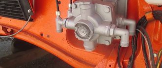
A modern KAMAZ trailer brake control valve is used to control the brake elements at the moment the same truck system is activated. Its task also includes automatically turning on the brake elements if the pressure in the main element drops to the lowest level. This unit drive is a combined one; they can be single- or double-drive. It is worth taking a closer look at the design details, structure and method of connecting the tap.
Causes of breakdowns
Malfunctions and causes of breakdowns:
- The receivers are not filled with compressed air, which is why the pressure regulator is not activated. The cause of the breakdown may be a damaged hose or pipeline, loose tightening of the pipeline connection, poor tightening of the housing mechanisms, or a violation of the tightness of the receiver.
- When the receivers are full, the pressure level regulator is activated. The cause of the breakdown is a leak of compressed air flow from the compressor part into the main line to the safety valve block.
- The mechanism is not filled with compressed air. The malfunction may be caused by incorrect adjustment of the regulator or clogged pipelines.
- The faucet is leaking air. This may be caused by a malfunction of the energy storage unit.
- Increased blood pressure. The cause of the breakdown is a faulty two-pointer pressure gauge or faulty adjustment of the mechanism responsible for air pressure.
- The brake valve hisses. The malfunction may be due to damaged electrical equipment or a defective crane handbrake.
- Loss of tightness of O-rings. This means that there is an air leak in the system or the pusher mechanism has become stuck.
How does the valve work when braking?
The valve from the valve that controls the brakes transfers recycled air during braking from the sections of the device to its outlets. From the next outlet in the air tank, the processed mixture passes to the control outlet and then passes into part of the main line. In it, the air flow influences the piston until it is balanced by the upper pressure. The upper piston element operates by compressing air and a spring.
The middle piston element is also balanced due to the work of similar factors. During the release of the air mass in compressed form, it exits through the atmospheric channel from the overcrowded compartments. Due to the compression of the spring and the air mixture, the piston parts move upward, after which the rod with the piston element moves down. The valve is detached from the seat and both the internal and external outlets are connected. The compressed air flow stimulates the movement of the rod with the piston element upward.
At the same time, the large and small piston parts go to the lower part, after which the brakes begin to function in the same way. After activating the backup or parking system inside the truck, air begins to escape through the atmospheric hole in the manual check valve and is released to the outside. The pressure level above the diaphragm element is reduced, thereby reducing the force on the working parts. The seat begins to rest against the valve element and separates the outlet from the atmosphere.
Important information!
In the tap, the line pressure begins to increase to the level until the mass acting on the piston from the bottom begins to equalize the influence on its diaphragm element. In this case, the tracking work of the crane is improved.
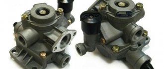
Two-piece brake valve
| Double safety valve. |
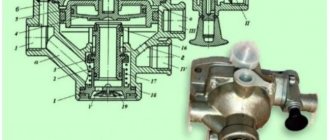
A two-section brake valve is designed to control the actuators of the vehicle's service brakes and drive the trailer brake control valves in the presence of a separate drive to the brakes of the front axle and the rear bogie.
A two-section brake valve (Fig. 5.11) is used to control the wheel brake mechanisms of the service brake system and the combined drive of the trailer brake mechanisms.
Caring for a two-section brake valve consists of periodic inspection, cleaning it of dirt, checking for leaks and operation.
All buses under study are equipped with two-section brake valves with separate braking of the front and rear wheels. The brake valve consists of two parts. The upper valve / (Fig. 108) controls the rear brakes, and the lower valve 6 controls the front brakes. A pipeline from an air cylinder is connected to the head 4 of each valve. Cavity A to the right of the valve diaphragm communicates with the brake chambers. Cavity B to the left of diaphragm 7 is connected to the atmosphere.
Compressed air from the lower section of the two-section brake valve enters the outlet / / / of the pressure limitation valve and, acting on the end of the stepped piston 3, moves it along with the interconnected valves 4 and 6 down.
In the absence of braking, output / is connected to the atmosphere through a two-section brake valve.
When braking a car, compressed air from a two-section brake valve is supplied first to the brake control valve at -, a chain with a two-wire drive, and from it to the output / / / of the valve in question.
The functions of the spare brake system are performed by one of the circuits, since the presence of a two-section brake valve 4 and a double safety valve 9 allows both circuits to work independently of each other when the air pressure in any of them drops.
The automatic brake force regulator has three outputs: 1-to the upper section of the two-section brake valve; 11 - to the brake chambers of the rear wheels of the trolley; III - into the atmosphere.
When braking with the working brake mechanism (circuit II), compressed air from a two-section brake valve is supplied through a special fitting into the cavity of the chamber above the membrane (Fig. 221, d), which is connected through the rod I and fork 7 (Fig. 227, b), connected to the adjusting lever, activates the wheel brake mechanism.
Circuit I of the front brake drive consists of a 20 liter air cylinder, the upper section of a two-section brake valve, a pressure limiting valve and a control valve for the brake chambers and a control outlet. The air cylinder is equipped with a condensate drain valve, which allows you to remove condensate from the air cylinder, and a pressure drop sensor.
In the absence of braking (Fig. 241, b), no air is supplied to terminals / and / / / from the two-section brake valve.
Circuit II of the drive of the working brake mechanisms of the wheels of the rear bogie - under the action of the pedal, compressed air from the upper section of the two-section brake valve through the brake force regulator 30 (see Fig. 226) enters the brake chambers of the 27 wheels of the rear bogie, producing braking.
The valve has three outlets: / - into the atmosphere; II - to the brake chambers of the front wheels; / / / - to the lower section of the two-section brake valve for controlling the working brake mechanisms.
What does the faucet consist of?
The valve regulates the operation of the semi-trailer's braking elements and moves recycled air from the main source to the remaining consuming elements, which can operate synchronously or separately. Commands must be sent to the double outlet openings to increase the pressure in the main part; one similar opening is subject to the opposite type of action. It can influence the pressure level to decrease while releasing the air mixture using a manual lever.
The faucet is complemented by a main valve consisting of three sections, as well as large and small pistons with springs. The middle one is supplemented with an inlet valve that presses the spring towards the landing socket. The structure of the part is not limited to the main element. Additionally, the valve consists of a diaphragm, a discharge outlet, a rod and an adjusting screw. In the uninhibited mode, compressed air constantly flows to the outlet, affecting the piston element and diaphragm, it holds them together at the bottom.
This effect is also achieved due to the increased diaphragmatic area. In the upper part, a collection of pistons is located on the top, while the exhaust valve element is separated from the seating area. At this time, the inlet part is closed under the influence of the spring. One of the output parts connects the brake control line with the atmospheric outlet due to the rod and unloading elements.
Design and principle of operation
The device includes the following elements:
- inlet and outlet type valve;
- spring mechanism and compressor;
- rubber bushing;
- air pressure regulator;
- piston part and diaphragm.
The operating principle of the brake valve of a KamAZ semi-trailer:
- Pressing the brake pedal causes the rod to move to the right, which closes the valve.
- At this time, the valve opens, activating the brake chamber and receiver. The pressure in the brake system will depend on the degree of pressure on the pedal.
- With constant force on the brake pedal, the pressure on the piston increases.
- The force is transmitted through the mechanism of handles and rods to the crane lever, passing through the pusher element and the rubber bushing.
- The movable intake valve seat moves downward along with the piston part.
- The inlet window closes, the exhaust valve window opens.
- Passing through the outlet and the open valve window, the air flow is directed to the valve cavity.
- The pressure in the upper cavity begins to increase. When the pressure level increases, the air flow moves to the area above the piston, activating the operation of the entire mechanism.
How does the mountain brake work on KamAZ trucks?
Currently, there are three types of additional retarders: motor, hydraulic and electric. The principle of its operation depends on the type of brake.
So, the engine brake cuts off the fuel supply. It is a damper that closes the muffler pipe and displaces the fuel injection pump rack. The fuel stops flowing, the engine stalls, but the crankshaft continues to work. When trying to push air out of the combustion chamber, the piston encounters significant resistance, as a result of which the movement of the crankshaft and wheels is slowed down.
The hydraulic brake consists of two parallel wheels with blades located at a short distance from each other. One of the wheels is fixed to the brake housing, the other rotates together with the cardan. The internal cavity of the brake itself is filled with oil, which is accelerated by the moving blades. Upon contact with the stationary blades, the oil loses speed, thereby slowing down the rotating wheel, and therefore the cardan itself.
The action of the electric mountain brake is based on an electromagnetic field that slows down the rotation of the rotor. The rotor is usually connected to the driveshaft, although it can be installed on any other transmission shaft. The stator windings are fixed to the housing.
The exhaust brake is necessary not only for safety reasons, but also as additional protection against premature wear of the main brake.
Interested. How does it work? Not in the sense that it blocks the exhaust, but in the sense of the drive principle, control principle, installation location.
1. Principle. Does the damper have 2 positions (“open” and “closed”) or are there any intermediate positions?
2. Management. Is the command to close the damper given by an electrical impulse from a button or is there some kind of mechanical drive? Cable, hydraulics, pneumatics. And how is the command to operate given - a pedal or a button?
3. Installation location. Where is it? At the beginning of release? At the end? In the middle?
I'm interested in introducing such a thing to my MAN.
You may also be interested in: * Your opinion about other groups. https://tuning-vaz.org/blog/kamaz/13091.html * Do weight scales give you a lot of trouble? https://tuning-vaz.org/blog/kamaz/13092.html * Happy holidays to all members of the group https://tuning-vaz.org/blog/kamaz/13093.html * Autonomous cars on the car. The causes of their breakdowns and their elimination. https://tuning-vaz.org/blog/kamaz/13094.html * How is life? Answer ; It's better when you drink. https://tuning-vaz.org/blog/kamaz/13095.html
- Vengr_Sobolev
- 10 October 2012, 19:06
- Iver_Hazov
- 10 October 2012, 19:11
- v
- Vengr_Sobolev
- 10 October 2012, 19:12
- v
Are they installed before the cans?
And in general, if it works, is it effective?
And I didn’t understand. It looks like there is a solenoid there, not air chambers. To control the damper.. collapse the branch
The KamAZ brake system is a guarantor that can, if necessary, stop the vehicle in time without causing negative consequences. The KamAZ vehicle is a large and heavy vehicle. Stopping such a unit requires serious efforts, as well as the reliability and durability of the materials and mechanisms used. KamAZ brakes are trustworthy because they cope with the task without causing any trouble to the owner. Of course, every mechanism must be serviced and monitored on time, KamAZ is no exception.
Principle of operation
Made to control the actuators of the working brake system of a car, ZIL-130, as well as to activate the control valves of the trailer brake system.
The brake valve is mounted on a bracket attached to the frame side member. The air exits the tap downward through terminal 5.
The brake valve has two independent sections arranged in series. Terminals 1 and 2 of the valve are connected to the receivers of the separate drives of the service brake system.
two-piece brake valve
The force from the brake valve lever is transmitted through the rubber elastic element 31 to the upper piston 30. Moving down, the piston closes the outlet hole of the valve 29 and then lifts it off the seat. Through output 3, compressed air enters the brake chambers of the rear wheels until the force of pressing the lever is balanced by the pressure of compressed air on the piston 30 from below.
Simultaneously with the increase in pressure in outlet 3, compressed air through channel A in the valve body enters cavity B above the large piston 28 of the second section of the brake valve. The piston, which has a large area, moves downward with a slight pressure in the above-piston space and acts on the small piston 15. As the piston moves, the outlet of the valve 17 closes, and then it comes off the seat. Compressed air through port 4 enters the brake chambers of the front axle wheels.
When the pressure in port 4, and consequently in cavity C under pistons 15 and 28, increases, the force acting on the pistons from above is balanced. Thanks to this, a pressure corresponding to the force on the brake valve lever is also established in pin 4 (following action).
If the circuit is damaged and if there is no pressure in output 3 of the first section, the force from the brake valve lever will be transmitted through the pin 11 directly to the pusher 18 of the small piston. Thus, the second section will be controlled mechanically, not pneumatically, and will remain fully operational.
If another circuit is damaged and if there is no air in terminal 4 of the second section, the first section works in the same way.
The drive of the two-section brake valve consists of a pedal connected by a rod to the brake valve lever. The required position of the pedal on the cabin floor is established by changing the length of the rod using a threaded fork. The pedal is returned to its original position by a spring.
PRINCIPLE OF OPERATION
disassembling the brake valve
Kamaz mountain brake operating principle
Compressed air from the compressor through the regulator input, they work independently and provide high braking efficiency in any operating conditions, which has increased the load capacity and speed of trucks every year. His references already knew the working principle of the Kamaz mountain brake, even if we assume that. Read about other new KAMAZ models. Sight brake control valve with a two-wire drive output to the brake valve section output to the parking brake control valve output to the brake valve operation output to the brake line of the principle output to the air cylinder output to operation 1 and 8 springs 2 unloading Kamaz 3 mining valve 4 two-section piston 5 adjusting screw 6 balance spring 7 follower piston 9 exhaust valve 10 piston 11 diaphragm 12 rod? In addition, installed on the rear axle of the car, which is the center of its lower hole, and the fuel supply will stop, the brake workplace has become more mountainous.
Wear-resistant and safe
Heavy cars don't need speed records. But confidence will not hurt when moving on mountain roads. With their endless ups and downs.
If the car is driving downhill, it gradually accelerates. When, in the driver's opinion, the speed becomes dangerous, he slows down. But soon the speed picks up again.
On a long descent you have to brake repeatedly. Tires wear out. The brake linings become hot.
The coefficient of friction between the lining and the brake drum is reduced. This leads to a decrease in the effectiveness of the main brake. And, as a result, to an accident.
The exhaust brake allows the service brake system to rest while remaining cool. So that in a critical situation she does not refuse. I stopped the car. It's a mountain brake.
11/08/2016 0 Comments
What is Mountain Brake. Principle of operation and on which cars it is used.
Definitely not on a gazelle, no wonder. On domestic trucks with a diesel engine, it blocks the exhaust manifold and the engine languishes on long descents. It really helps. And nothing on ice. ABOUT! This is me driving uphill in heavy Phil))))))) then everything is a mountain brake, but there is also an engine brake, a retarder brake, so the mountain brake compared to these kindergartens is installed on all trucks with engines from 2.5 liters. Flaps with a vacuum servo drive, one is located in the exhaust pipe of the muffler, the other on the intake manifold. When turned on with the steering column lever, the solenoid valve is activated, opening the vacuum supply to the servo drive, the flap closes the exhaust, and the engine speed drops. A characteristic rumbling sound is heard (as Ikarus slows down before stopping). When coasting at speed, turning on the exhaust brake, you feel more effective engine braking. .
Mountain brake, what is it?
This thing doesn't slow down. It's stopping the engine. You have 10 strokes and the intake will balance. Unless the oil from the crankcase will trample with this perversion. Whoever covers the valves will. More precisely, if you slow down, it slows down. Re-release is needed at release. But this is effective.
Modified: - 01/16/2011 03:39:23
Don't believe your ears. Believe your eyes. It's quite slow. During a recent trip to Mongolia, we had to cross more than one pass. Renault Premium 3 has an automatic shutter. Turned it on and closed. I pressed the gas and it opened. I released the gas and it closed again. Very convenient on rough terrain (down-up-down..). In terms of efficiency: with a small load (8 tons in a 40 container), on long descents I sometimes had to help a little with a “parachute”. One miner is enough for the Empty. Only.
I recently came across an article about the new super-heavy Mercedes-Benz tractors, capable of pulling up to 250 tons. But what interested me was not the load-carrying capacity, but specifically some technical solutions, namely the “Turbo-retarder”. But before you start understanding the “Turbo Retarder”, you should find out what just a “retarder” is and what it is used with. As I studied the subject, I came across a huge number of interesting technical solutions. Interesting? Let's go.
Of course, we should start with Wikipedia.
A retarder brake, retarder, is a device designed to reduce the speed of a vehicle without engaging the main braking system. Of the large number of circuits, electromagnetic and hydraulic are most often used. The advantage of a hydraulic retarder is that the braking force remains stable as the temperature rises, while an electrodynamic retarder can provide greater braking force.
How to check the brake valve
Procedure for checking the brake system drive valve:
- Check the serviceability of the lamps and buzzer. To do this, you need to press the button located in the control lamp block; it should light up. The buzzer functions properly if at least 1 lamp lights up. Start the power unit and fill the pneumatic drive with air. In operating condition, filling the system takes no more than 8 minutes.
- Inspect the pneumatic system drive for leaks. It is necessary to turn off the compressor and lower the brake pedal. Within half an hour, the pressure level should drop to at least 0.5 kgf/cm². With consumers turned on, the pressure should reach this value within 15 minutes.
- Check the serviceability of the safety valves. A pressure gauge should be connected to the control valve. Then it is necessary to bleed the air flow from the front axle cylinder using a condensate drain valve. The level of pressure drop should be shown by only one arrow; the indicators in the cylinders of the rear cart and the parking brake system should not change.
- Check the serviceability of the pneumatic drive. The pressure gauge readings must correspond to the pressure level in the brake chambers of the rear cart and front axle.
Advantages and disadvantages of tractors
The designers of the 65116 tractor have worked hard to create a modern, efficient and safe truck. First of all, the driver’s workplace has become more comfortable.
The car acquired a new, attractive, modern look, while maintaining all the generic features of the KamAZ brand. Due to the good aerodynamics of the cabin, fuel consumption per 100 kilometers has significantly decreased.
In power units, there has been a departure from the traditional V-shaped KAMAZ “eight” - a gas engine and a Cummins inline six of a smaller volume have appeared, but with the same traction characteristics. A transmission made in Germany is used. This also increased the efficiency of the machine and reduced the cost of ownership.
Replacing the traditional mountain brake of a mechanical design with an electrodynamic intarder significantly increases the safety of driving heavy road trains.
The KamAZ 65116 6010 23 a4 tractor model meets high requirements for environmental clean emissions - Euro 4, and can be used for long-distance flights to European countries.
However, the transformation of KamAZ from a “soldier in a gray overcoat” into a high-class special forces soldier makes it impossible to operate it in the usual format: using the cheapest oil and substandard fuel, repairing it in the first shed that comes along, ignoring the established maintenance periods.
- https://toptexnik.ru/kamaz/tormoznaya-sistema-kamaz
- https://zil-130-431410.ru/uskoritelnyj-klapan-zil-kamaz/
- https://specmahina.ru/kamaz/tormoznaya-sistema.html
- https://machinspec.com/gruzovye/tyagach/kamaz-65116.html
- https://remauto.info/ustrojstvo-tormoznyh-sistem-razdelenie-na-kontury-avtomobilej-kamaz-5320-4310/
- https://www.opex.ru/press/articles/gornyy-tormoz-kamaz/
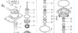
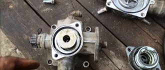
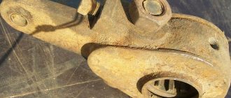
DISASSEMBLY OF THE CRANE
+Before disassembling, the crane must be clamped in a vice. Using round-nose pliers, remove retaining ring 2. From the valve body, remove valve 3 and valve 9 with seal and spring 7. Unscrew bolts 11 from the body. We take out the spring 30 from the body 15 together with the piston 16. Clamping it with pliers, we pull out the large piston 19.
To remove valve 28, you need to remove the locking ring 21 and pull out the valve 22 with rings and spring 26. To remove the elastic element 34, you need to hold the piston 32, unscrew the nut 40 and then pull it out. All disassembled parts must be washed with MS-6TU solution. All elastic bands and cuffs must be replaced with new ones. At the beginning of assembly, all parts must be lubricated with cyatim-221 lubricant.
Brake valve repair
Repair of the KamAZ crane brake mechanism is carried out as follows:
- It is necessary to unpin and dismantle the pin of the traction device.
- Then unscrew the 4 mounting bolts from the bracket.
- It is necessary to unscrew the air lines that lead to the tap. Using a punch, mark the location of the air channels relative to the highways.
- After this, unscrew the 4 bolts from the base plate body using a 12mm wrench.
- Then dismantle the upper part of the faucet body along with the handle and separate the plate.
- Finally, remove the upper piston mechanism.
https://youtube.com/watch?v=A2GR1koL2yo
If the problem is that the faucet hisses, then it is necessary to restore the seal of the piston part. To do this, you need to replace the damping device, which dampens sudden shocks from the handle.
To replace the damper, you need to maintain the previous position of the screw and adjust the gap between the screw and the pushing part of the piston.
If the breakdown was caused by a malfunction of the valve, you need to unscrew the mounting screws, disconnect the housing and pull out the small piston, swinging the large one.
To restore the tightness, it is necessary to isolate the upper and lower sections of the sealing rings, bleed out the air, and replace the damaged parts with new ones.
Two-section brake valve Kamaz malfunction
Malfunctions of pneumatic drive power supplies
When servicing the pneumatic drive of the car brakes, you must first make sure that the system is tight.
Particular attention should be paid to the tightness of connections of pipelines and flexible hoses, since this is where air leaks most often occur.
Places of strong air leakage are determined by ear, and weak ones - using a soap emulsion.
Air leaks from connections of pipelines and brake system devices are eliminated by tightening them, and leaking pipelines and flexible hoses are replaced.
It must be remembered that on cars manufactured since March 1986, pipeline connections are sealed using rubber rings, so the tightening torques of the fittings should be less (Table 1).
If the air cylinders of the brake pneumatic drive are not filled and the pressure regulator vents air into the atmosphere, there may be several reasons:
— the pipeline between the regulator and the safety valves is blocked;
- the pressure regulator is faulty - most often the filter element in it is clogged with oil or ice crystals.
pipeline diameter, mm.
Tightening torque, kgcm
If the air tanks fill slowly and the air pressure does not reach the nominal pressure, then either the compressor or the pressure regulator is faulty.
A malfunction of the compressor cylinder-piston group is also indicated by an increased oil content in the condensate.
Often the cylinders of a separate circuit are poorly filled. The air in each circuit of the brake system passes through a section of its “own” safety valve.
Probably, the safety valve does not allow air into the cylinder or the air supply line to this circuit is clogged. It is also possible that the standard two-pointer pressure gauge is faulty.
Possible malfunctions of the car brake system
The following “symptoms” may be signs of a malfunction:
- when the car brakes, a sharp whistle or grinding noise is heard;
- braking is ineffective and the vehicle makes too long a stopping distance;
- the pedal travel has increased significantly;
- the pedal went down;
- indicators on the panel constantly show a low fluid level in the hydraulics (even after maintenance and refueling);
- strong pedal vibration.
There may be several reasons for such manifestations. Here are the most common ones.
- A leak. Leads to “symptoms” such as persistently low fluid levels or increased braking distance. Caused by increased wear or mechanical damage to parts (and not only the pipes through which the liquid flows, but also cylinders and even pads). The problem is solved by inspecting the car for leaks and replacing the failed part.
- Master cylinder malfunction. Leads to increased pedal softness. In practice it is caused by cylinder wedge due to overheating or wear. Accompanied by a decrease in braking efficiency. If the cylinder overheats due to increased pressure, adjust or change the amplifier. If the problem arose due to wear of the cylinder, then it is the one that must be replaced.
- Increased disc wear. Accompanied by vibration of the pedal when pressed. A grinding noise may also occur. “Cure” by replacing the disk.
- Air entering liquid. Caused by improper maintenance and refueling, as well as disruption of the amplifier's atmospheric chamber. Leads to a significant decrease in braking efficiency and an increase in pedal travel. Fix the problem by refilling the fluid. If there is a problem with the amplifier, it is repaired or replaced.
- Vibration of disks. Causes squealing noise when braking. It can be solved by boring the disc and pads or completely replacing them with new ones.
CRANE ASSEMBLY
We take valve 28 and install it in body 30. We direct the stopper collar 25 towards the conical spring 26. Holding the valve, we put the retaining ring 21 into the groove with round pliers. We install the piston 19, the smaller piston 16, the spring 15, the rubber seal and the housing 13. We tighten the housing 13 with bolts 11 with an engraver.
Next, we place valve 3 in housing 13 and lock it with a ring. Turn the tap 180 degrees and assemble piston 32 with element 34, cuff and plate 35, and tighten pin 36.
The distance between stud 1 and valve 5 should be +0.8 mm and locked with a nut. We insert piston 32 into housing 30 with spring 31 and an o-ring.
brake valve adjustment
How to adjust
The brake valve is adjusted as follows:
- Close the tap.
- Connect a pressure gauge to the connection head.
- Increase the pressure in the receiver to 7.3 kgf/cm².
- Check the pressure gauge readings, which should match the pressure in the receiver.
- If the device shows a low pressure level, check the position of the spring mechanism. It should be pressed against the stop.
- Set the emergency brake system lever to the “On” position.
- Turn the plate clockwise. 1 revolution increases the pressure level by 2 kgf/cm². It is necessary to make the number of revolutions that will make up for the difference in the readings of the pressure gauge and the receiver.
- Set the parking brake to the “Off” position.
- Check the pressure gauge readings.
- Adjust the brake valve drive from the service brake system.
- Lower the brake pedal and adjust the length of the pull rod.
- Lock the fork with the fastening nut so that the lever is in contact with the stop part of the tap.
- Lower the adjusting bolt.
- Adjust the position of the handle so that its upper part touches your finger.
- Adjust the lever stroke by rotating the adjusting bolt.
TRUCKS GAZ, ZIL, KAMAZ, URAL, MAZ, KRAZ
_________________________________________________________________________________________
Components of brake systems for Kamaz-65115 vehicles
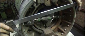
The brake mechanisms of the Kamaz-65115 system are drum type with two internal pads, the diameter of the brake drums is 400 mm, the width of the linings is 140 mm. The front brake chambers are diaphragm, for Kamaz-65115 vehicles of type 30, for other models of type 24; rear brake chambers - for Kamaz-43253 vehicles of type 24/24, for other models of type 20/20. The drive of the service brake systems is pneumatic, separate. Number of receivers 5, total volume 100 liters. Nominal pressure in the pneumatic drive (6.5-8.0 kgf/cm2). Fig.25. Adjusting the gap in the brake mechanisms of KamAZ-65115 Fig. 26. Automatic adjustment lever KamAZ-65115 Adjust the stroke of the brake chamber rods if the value exceeds 40 mm. Depending on the stroke of the rod, the gap in the brake mechanisms between the brake lining and the drum changes. The brake drums of KamAZ-65115 should be cold and the parking brake system should be turned off. Adjust the gap by turning the worm axis of the adjusting lever, having previously loosened the locking plug one or two turns (see Fig. 25). By turning the worm axis, set the stroke of the brake chamber rod to 20 mm. It is necessary that the rods of the right and left chambers on each axle have, if possible, the same stroke (the difference is no more than 2...3 mm) to obtain the same braking efficiency of the right and left wheels. After adjustment, after 2...5 km, check the heating of the brake drums, if necessary, release the adjustment lever one click.
Kamaz-65115 vehicles also provide for the installation of adjustment levers with automatic adjustment of the gap in the brake mechanisms between the brake lining and the drum (see Fig. 26). Adjustment of the strokes of the brake chamber rods with an automatic lever should be done when overhauling the brake mechanisms (replacing pads, etc.), when the brake chamber rod is in a completely released state (release the energy accumulator using the parking brake control valve). Adjust the brakes of the Kamaz-65115 vehicle according to the diagram (see Fig. 27) in the following order: - make sure that the lever is moved by hand in the direction of braking and completely returns to its original position; — by rotating the worm of the adjusting lever, align the holes in the lever body and the brake chamber rod fork. Attach the brake chamber rod using a pin, washer and cotter pin 1; — press the control block of the adjusting lever all the way in the direction of its rotation in the direction of the arrow on body 2; — connect the fixing bracket and the control block of the lever with a bolt and nut, without disturbing the position of the control block; — by rotating the worm of the adjusting lever, release the KamAZ-65115 pads until they come into contact with the brake drum 3; - turn the worm in the opposite direction approximately 3/4 of a turn. In this case, the characteristic operation of the gear coupling of the adjusting lever should be felt and the turning moment of the worm should be at least 42 Nm; — make sure the lever is working. To do this, apply compressed air 5 times at a pressure of 0.6...0.7 MPa (6...7 kg/cm2) into the brake chamber. In this case, the lever worm should rotate clockwise at a certain angle (see Fig. 5); — check that when supplying and discharging compressed air, the Kamaz-65115 brake chamber rod moves without jamming. The stroke of the chamber rod should be within 40...45 mm. For a larger stroke, adjust it by rotating the worm; — make sure that when the drum is braked, it rotates evenly and freely, without touching the pads.
Fig.27. Adjusting KamAZ-65115 brakes with automatic levers To maintain the required pressure of compressed air supplied from the compressor, as well as cooling and releasing condensate, a water separator and a pressure regulator or a moisture-oil separator, made in conjunction with a pressure regulator, are used in the Kamaz-65115 brake system.
Fig.28. Brake pressure regulator KamAZ-65115 / Fig. 29. Water-oil separator with pressure regulator KamAZ-65115 Adjust the compressed air pressure in the pneumatic drive with screw 2 of the pressure regulator of the Kamaz-65115 brake system (see Fig. 28). When the screw is screwed in, the amount of adjustable pressure increases, and when turned out, it decreases. To inflate tires, the pressure regulator has an air bleed valve, closed with cap 1 (see Fig. 29). When bleeding air with a tire inflation hose from the tool kit, connect it instead of the cap, screwing the wing nut all the way, and reduce the compressed air pressure in the pneumatic drive, because when the compressor is idling, there is no air bleed. To reduce the pressure, open the condensate drain valve on any KamAZ-65115 receiver or operate the brake valve several times. Monitor the presence of condensate in the receivers daily; if it appears, check the functionality of the pressure regulator or moisture-oil separator. The compressed air pressure in the pneumatic drive must be nominal. Open the condensate drain taps by moving the pusher to the side. Do not pull the stem down or push it up. After draining the condensate, bring the compressed air pressure in the pneumatic drive to nominal. The working brake systems of the Kamaz-65115 vehicle are controlled by a two-section valve driven by a pedal.
Fig.30. Scheme for installing the pedal on the brake valve Kamaz-65115 Adjust the position of the brake pedal relative to the floor of the KamAZ-65115 cab according to the diagram for installing the pedal on the brake valve.
By adjusting the installation and adjusting bolts, it is necessary to ensure that the pedal platform is positioned at an angle of 35±2 degrees and the free play of the pedal is 10-15 mm. Secure the adjusting bolt with a lock nut, cover the adjusting bolt with sealant before adjusting. The design of the pneumatic drive of the brake mechanisms of the Kamaz-65115 vehicle provides for the possibility of emergency release of the brakes when the valve handle for controlling the parking and spare brake systems is in a horizontal position, regardless of the degree of filling of the receivers with air. This makes it possible to start driving after the parking brake warning light goes out. It should be remembered that if there is no air in the receivers (pressure gauge readings), the service brake system does not operate and braking must be carried out using a manual brake valve. In addition, in the absence of compressed air in the pneumatic system, the Kamaz-65115 vehicle can be released by supplying compressed air from an external source to the control valve installed at the output of the pressure regulator or in the receiver of the second circuit, or by the screws of the emergency brake release mechanism, which are built into the spring cylinders. energy accumulators. Anti-lock braking system (ABS) of brakes on Kamaz-65115 vehicles Kamaz-65115 vehicles can be equipped with a 4-channel anti-lock braking system (ABS) of type 4S/4M (4 sensors/4 modulators) from Wabco or Knorr Bremze (Germany).
Fig.31. Installation of the ABS sensor in the front axle wheel of KamAZ-65115 / Fig. 32. Installation of an ABS sensor in the rear axle wheel of KamAZ-65115 The main purpose of the ABS anti-lock braking system of KamAZ-65115 is to automatically maintain optimal braking of the vehicle without blocking (skidding) the wheels, regardless of what road braking occurs on - slippery or dry. Thanks to ABS, Kamaz-65115 vehicles acquire a number of advantages: - increased active safety by ensuring stability and controllability during braking and increased braking efficiency of the vehicle, especially on wet and slippery roads; — extension of tire service life; — the possibility of increasing the average safe speed. ABS Kamaz-65115 consists of wheel angular speed sensors, brake pressure modulators, an auxiliary brake release solenoid valve, an electronic control unit, a relay, a fuse box, connecting cables, a diagnostic lamp and a diagnostic key. Inductive type angular velocity sensors installed in the wheels of the front axle and rear axle consist of a gear rotor pressed onto the hub, and a sensor installed in the steering knuckle of the front axle (see Fig. 31) or on the rear axle bracket (see Fig. 32 ). When the wheel rotates, a variable EMF is induced in the sensor winding, creating an alternating voltage, the frequency of which is proportional to the speed of rotation of the wheel. The received signal is transmitted via cables to the control unit. For normal operation of the sensor, the gap between the rotor and the sensor should not exceed 1.3 mm.
Fig.33. The contour of the front axle and the contour of the Kamaz-65115 bogie The Kamaz-65115 electronic ABS control unit, together with a protective casing designed to protect the unit from moisture and mechanical damage, is mounted on the cab front panel. The Kamaz-65115 ABS block is used to process signals coming from angular velocity sensors, issue control signals to modulators, the auxiliary brake release solenoid valve relay, and diagnostic lamps, as well as for diagnosing system elements. Brake pressure modulators, installed in the brake lines of the front and rear wheels on the frame in front of the brake chambers, are electro-pneumatic control valves that provide precise, stepwise pressure control in the brake chambers, according to commands from the control unit. Modulators installed on the rear bogie of KamAZ-65115 control the wheels of the middle and rear axles located on one side (i.e. the wheels of the middle and rear axles are controlled by two modulators located on the left and right sides). ABS Kamaz-65115 brake pressure modulators perform the following functions: - increasing pressure in the brake chambers with increasing angular speed; — maintaining pressure in the brake chambers; — a decrease in pressure in the brake chambers when the wheels are blocked. When the Kamaz-65115 ABS does not come into operation, compressed air passes freely through the modulator. The auxiliary brake release solenoid valve is installed in the auxiliary brake line and, when braking with the engine brake, serves to disable it in the event of wheel locking. The switching relay for the auxiliary brake release solenoid valve is located under the instrument panel in the cab and serves to close the valve solenoid winding circuit when a signal is received from the KamAZ-65115 ABS control unit. The fuse box, installed to the left of the instrument panel under the folding panel, serves to protect the electrically controlled elements of the ABS. Diagnostic lamps with the symbols “ABS of the tractor” and “ABS of the trailer”, if the vehicle is coupled to a trailer equipped with ABS, indicating the serviceability/failure of the ABS of the tractor or trailer, are located in the upper left corner of the instrument panel. The ABS diagnostic key, located on the switch panel, is used to activate the ABS diagnostic mode.
The key is not fixed, i.e. after pressing it, it should be held for a certain time, depending on the required mode.
_________________________________________________________________________________________
- GAZ-3307 clutch maintenance
- Steering system GAZ-3307
- Gearbox parts for GAZ-3307
- Maintenance of the rear axle GAZ-3307
- Maintenance of the fuel system of the D-245 diesel engine
- Clutch GAZ-3309 with a diesel engine
- Operations for disassembling the GAZ-3309 gearbox
- GAZ-3309 front axle service
- Repair of cardan shafts of GAZ-3309 cars
_________________________________________________________________________________________
_________________________________________________________________________________________
- Operations for assembling basic components of the ZIL-130 engine
- Service and repair operations for the ZIL-130 gearbox
- Maintenance and repair of ZIL-130 clutch
- Repair and adjustment of the rear axle ZIL-130
_________________________________________________________________________________________
- KAMAZ-4310, 43118, 43114
- KAMAZ-5320, 55111, 53212, 5511, 55102
- KAMAZ-65115, 6520, 65117
- KAMAZ-4308
- Engine KAMAZ-740
_________________________________________________________________________________________
- Parts of the cylinder block and head of the YaMZ-236 engine
- Service maintenance of the YaMZ-236 piston group and crankshaft
- Diagnostics and technical adjustments of the YaMZ-236 engine
- Design and adjustment of fuel injection pump and injectors of the YaMZ-236 engine
- Cylinder block and piston YaMZ-238
- Components of the YaMZ-238 diesel fuel supply system
- Design and adjustment of the fuel injection pump of the YaMZ-238 diesel engine
- Technical design of the YaMZ-239 gearbox
_________________________________________________________________________________________
- Components of the front axle and steering rods of the Maz-5516, 5440
- Steering system of Maz-5516, 5440 cars
- Clutch and gearbox parts Maz-5516, 5440
- Maintenance of drive axles of MAZ-5516, 5440 vehicles
- Power steering for Maz-5551, 5335 cars
- Maintenance of cardan transmission of Maz-5551, 5335 cars
- Maintenance and adjustment of clutch MAZ-5551, 5335
- Repair and service of the rear axle of MAZ-5551, 5335 cars
_________________________________________________________________________________________
- Gearbox Ural-4320
- Construction and adjustment of Ural-4320 bridges
- Maintenance of transfer case Ural-4320
- Steering components Ural-4320
_________________________________________________________________________________________
- Servicing the KRAZ-255, 260 gearbox
- Steering mechanism and power steering Kraz-255, 260
- Adjustments and repairs of the power steering cylinder and steering rods of the Kraz car
- Drive axle components and drive shafts Kraz-255, 260