Any mechanism must have impact organs, as well as controls. The car clutch is no exception in this regard. Designed for short-term separation of the transmission and engine, it is an integral part of any vehicle and serves to ensure the ability to control the machine.
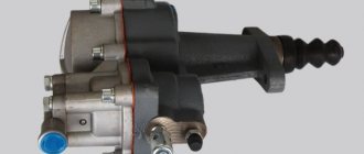
To transfer the impact from the driver to this mechanism, a hydraulic drive is usually used in passenger cars; One of the critical parts of such a device is the clutch master cylinder.
About the hydraulic drive device
To better understand what will be discussed, it is necessary to at least schematically imagine the design of such a drive. Let’s leave its purpose, structure, and role in the vehicle aside; in this case, the hydraulic drive itself is important.
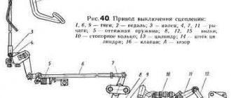
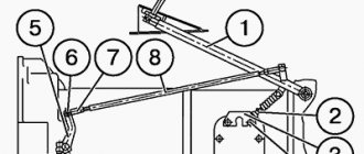
Its implementation, as an example, as one of the possible options, can be seen in the figure below. This is enough to understand the structure and operation of the clutch drive, as well as to understand its role and significance in the vehicle.
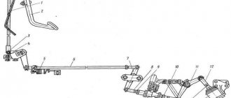
Of the drive parts in the figure, it is necessary to note the following components:
- reservoir for filling brake fluid (1), which is used as a filler for the hydraulic drive;
- clutch master cylinder (2);
- hydraulic pipes (3,4,5) and hose (7);
- clutch slave cylinder (8);
- pedal (6) and return spring (9).
What are the types of clutch drives and their operating principle?
The clutch drive on a car is designed to briefly disconnect the engine crankshaft from the gearbox, as well as to combine them, which are necessary for changing gears, as well as so that the car can move off and start moving.
Today, the following types of clutch drives are used in cars:
- mechanical clutch drive;
- hydraulic clutch drive;
- electrohydraulic drive.
The last of the above-mentioned clutch drives, unlike the first two, is used extremely rarely in cars and is used in robotic gearboxes. Therefore, we will not dwell on it more specifically, and let’s look at the first two.
Mechanical clutch drive
This drive is usually used in small passenger cars. It differs from other clutch drives in its low cost and simplicity of design, which consists of:
- clutch pedals;
- clutch cable;
- lever transmission;
- the mechanism responsible for regulating the free play of the clutch pedal.
How does a hydraulic drive work?
Without touching on the design of individual components of this mechanism, we can return to this a little later; it is enough to familiarize ourselves with its operation in a simplified manner. We will assume that the required amount of brake fluid is filled into the drive, it is in good working order and fully operational.
When you press the pedal (6), the force is transmitted through the rod to the clutch master cylinder (2). He perceives this force, and then transmits it through a system of tubes and hoses to the clutch slave cylinder. The latter, through the clutch fork and release bearing, disconnects the transmission from the engine.
Friction clutch - clutch
After engaging the friction clutch, joint acceleration of the driving and driven systems begins until normal flashes appear in the diesel cylinders, capable of starting the engine. After starting the engine, the MCX automatically disconnects the leading (from the starting motor to the MCX) and the driven (from the MCX to the working body) systems.
When the friction clutch operates in an oil bath, oil is constantly supplied under pressure to the rubbing surfaces.
Tractors use friction clutches, which use friction forces to transmit torque. Each clutch consists of a driving and driven part, a pressure device and a control mechanism. The driving part of the clutch is connected to the engine crankshaft and rotates with it, and the driven part is connected to the power transmission shaft. The control mechanism acts on the pressure device, which brings together and with a certain force presses the driven part of the coupling to the driving part. The resulting frictional forces transmit torque. When the torque increases sharply when the engine is overloaded, the driving and driven parts of the clutch slip relative to each other, thereby eliminating the transmission of increased torque and preventing possible breakdowns of transmission parts.
Tractors mainly use friction clutches.
Although the principle of operation of friction clutches remains the same, their design is very diverse. Clutches are classified according to a number of characteristics.
In non-planetary gearboxes, friction clutches have rotating hydraulic boosters that engage the clutch.
| Transmission mechanism. |
The transmission mechanism consists of a friction clutch, a freewheel and a release mechanism.
| Mixing drum diagram. |
The transmission includes: single-disc friction clutch; a gearbox that provides three rotation speeds in one direction and three in the opposite direction; helical-bevel gearbox installed at an angle of 18 to the horizontal; cardan shafts and chain drive. A V-belt pulley is mounted on the main shaft of the gearbox to drive a centrifugal water pump.
Wear of the driven and driving elements of the friction clutch occurs during the off-on period and possible slipping of the clutch in the fully engaged state. Due to the difference in mechanical properties, the wear rates of the driving elements (usually metal) and driven elements (combined with friction plastic or composite linings) differ significantly (by several orders of magnitude). This is explained by the fact that micro-roughness of the surface of the metal driving element of the clutch causes plastic deformations when sliding in the surface layers of the lining, and elastic deformations arise in them. According to the theory of fatigue wear, the intensity of wear significantly depends on the stress state in the zones of actual contact with the roughness of interacting bodies and during plastic deformations is several orders of magnitude higher than during elastic deformations.
| Kinematic diagram of the OMS cleaning machine. |
The working body is driven into rotation through a friction clutch, which allows the working body to be turned off at the moment of passing through the couplings and linings. It rotates under overloads in the event that the cutters meet an obstacle (seam), to some extent softening the blows, as a result of which the cutters and gear are protected from damage.
Disc brakes are used in presses with friction clutches. In these brakes, the pressing force on the discs is carried out by springs.
In all drives, the pump is started by the friction clutch of the drive motor.
How does the hydraulic drive work?
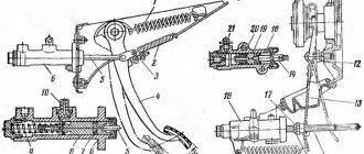
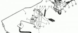
The design of the clutch master cylinder can be structurally designed in different ways, but in general the principle of operation is the same in all variants. As an example, the figure below shows a sectional view of the clutch master cylinder.
Among the main details are
- (2) - a pusher connecting the mechanism to the pedal;
- (3) master cylinder;
- (4) piston;
- plugs and return spring.
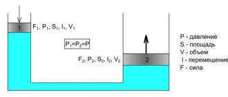
The figure shows that the clutch cylinder is divided into two parts by a partition. The upper half serves to fill the hydraulic drive with fluid entering the cylinder from the tank (5) and store its required working reserve. If everything is configured and adjusted correctly, then its level should be three quarters of the working volume.
The lower part serves as a working area. In the initial state, the piston (4) is pressed against the dividing wall by a spring, a gap A is formed between the pusher and the piston, and through it the liquid fills the working area.
When you press the pedal, the pusher, moving, closes gap A, the flow from the upper part to the lower part stops, the piston begins to move, transmitting force from the driver’s foot through a system of tubes and hoses to the working cylinder.
Due to the difference in the diameters of the piston and the outlet hole, its value increases, this becomes sufficient for the clutch to operate. This drive design makes it possible to lightly press the pedal to provide the required force to operate the entire mechanism.
When the pedal is released, the piston, under the influence of the spring and the pressure existing in the system, returns to its original position, and the pusher moves there, thereby restoring free penetration of liquid between the two parts of the cylinder.
Stages of work execution
Replacing the clutch on a GAZelle with your own hands begins with dismantling work.
The car should already be on a pit or lift at this time. The seal at the gear lever is lifted and the cap located at its base is unscrewed. After this, the lever can be pulled out with some force. Literally everything should be disconnected from it; the brake wires and the speedometer cable are disconnected from the box. The work in the cabin is completed, you can go down under the car. All work on replacing the clutch on a GAZelle should be carried out carefully so as not to damage nearby components.
Stage 1
The slave cylinder is connected to the starter - first of all you will need to disconnect them. The released cylinder rises up along with the pusher; there is no need to remove the hose from it. If the clutch fork on a GAZelle is being replaced, then the main part of the work can be considered completed, since it has become possible to remove it by unscrewing just one bolt. After this, the lower part of the crankcase is removed, the bracket used to connect the muffler pipes will become visible - it will need to be removed.
Stage 2
Now you need to remove the box. This can be done by unscrewing its fasteners. It is removed along with the coupling itself. The seals located between the clutch housings and the gearbox are dismantled. Next, you can try to find special marks for alignment on the motor flywheel and the pressure housing. They may not be there, then you should apply them yourself. The casing and flywheel are unscrewed, and it is necessary to gradually turn the crankshaft by hand. This is the stage of replacing clutch discs on a GAZelle - they can be removed through the hatch.
Stage 3
It is now possible to replace the GAZelle clutch master cylinder; if this is not necessary, you can simply remove it by disconnecting the hose from it and draining the entire compound. True, you will need to disconnect the pusher from the pedal - this is done simply. Installation of the other unit, of course, is carried out in the reverse order. New grease is added to the input shaft ball bearing in advance. When installing the casing, do not forget that the marks - original or applied yourself - must be aligned.
At this point, the main stage of work on independently replacing the clutch on a GAZelle can be considered completed. But in addition to replacement, adjustment of the GAZelle clutch is also required. A special tool is used to align the disc and crankshaft. It is inserted into the driven disk, which has a special hole, making sure that the tool used also fits into the bearing hole on the flywheel. How this is done in practice can be seen in the video:
Typical faults
Despite its simplicity, the master cylinder can also be a source of serious trouble. The most common causes of the defect may be:
- lack of working fluid;
- air entering the hydraulic drive system.
In the first case, you just need to check the liquid level in the tank; if it is insufficient, you need to add it to the set value. To avoid this, it is necessary to periodically monitor the position of the fluid in the tank during routine maintenance, as well as maintenance.
The reasons for air entering the master and slave cylinders, leading to clutch failure, may be cracks in the hoses, wear of parts, or leakage of the system at the junction of its various sections.
In order to restore the operability of the system, it is necessary to eliminate such sources of leakage and air entry into the line, the main and working cylinders, and also pump the entire system to remove air that has already entered from it. This procedure can be performed completely independently, without resorting to the help of a car repair shop. Due to the design features that the master cylinder has in different cars, it is difficult to describe this procedure correctly, although it can be briefly noted that it is carried out by pressing the clutch pedal. In this case, an additional hose is put on a special fitting or valve, through which the working fluid flows into a separate container with brake fluid.
Its level in the tank, to which the main cylinder is connected, should not fall below the set level, otherwise air may again enter. Along with the liquid, air leaves the system. When its bubbles stop releasing, we can assume that the system has been pumped and air has been removed from it. After this, everything is returned to its original state, the necessary adjustment of components and mechanisms is carried out (gaps and free movement are set).
The master cylinder is designed to transmit force from the pedal and convert its value to a value that should be sufficient to move the clutch fork. In this case, the clutch mechanism will operate and the connection between the engine and the wheels of the car will be broken.
Nuances of clutch operation
Often, drivers tend to associate unevenness and jerking when driving a car with clutch malfunctions. This logic is wrong in most cases.
For example, when a car shifts gears from first to second, the speed drops sharply. It is not the clutch itself that is at fault here, but the clutch pedal position sensor. It is located behind the clutch pedal itself. Sensor malfunctions can be eliminated through simple repairs, after which the clutch will again operate smoothly and without jerking.
Another situation: when changing gears, the car jerks a little, and when moving away it may stall. What could be the reason? Most often, the clutch delay valve is to blame. This valve provides a certain speed at which the flywheel can engage, regardless of how quickly the clutch pedal is "thrown" in. For novice drivers, this function is necessary, because... The clutch delay valve prevents excessive wear on the clutch disc surface.
Prices and stores for automobile discs and clutch linings in Moscow.
To find out how to buy a car clutch disc and lining in Moscow at an affordable price, use our service. You will find cheap products and the best deals with descriptions, photos, reviews and addresses. Prices and stores of inexpensive linings can be found in our online product catalog in Moscow, as well as find out where automobile discs and clutch linings are sold wholesale in Moscow. If you are a representative of a company or store, add your products for free.
- In stock
- Wholesale
- 04.08.19
RuMotors guarantees the high quality of the products offered. The company works under direct contracts with manufacturing plants and supplies the market with products that have all the necessary certificates, service coupons and technical data sheets.
- In stock
- Wholesale / Retail
- 09.07.19
Quantity per assembly unit: 1 We offer a large assortment of spare parts in stock! For consultation, you can always contact a company specialist.
From other regions
- In stock
- Wholesale / Retail
- 17.07.19
Our company supplies engines, diesel power plants and spare parts. We provide a full range of services in this area. Supply of original spare parts produced by YaMZ, TMZ, YAZDA, MAZ, URAL
- In stock
- Wholesale / Retail
- 24.06.19
Here you will find a complete set of car parts at amazingly low prices. Individual approach to each client.
- In stock
- Wholesale / Retail
- 17.07.19
Our company supplies engines, diesel power plants and spare parts. We provide a full range of services in this area. Supply of original spare parts produced by YaMZ, TMZ, YAZDA, MAZ, URAL
- In stock
- 21.07.19
The brake lining of the hoist is installed on the brake drum, which is structurally combined with the cooling fan of the hoisting motor. This pad (ferrodo) is used for the best braking
- In stock
- Wholesale / Retail
- 05.08.19
Spare parts for special equipment, municipal and road machines, brush disks, steel rollers, tupsa, spare parts for rollers DU-98, DU-47, loader TO-28, TO-18, Mitsuber, grader DZ-98, DZ-122, DZ- 143, for T130, T170, K700, MTZ spare parts and others.
- In stock
- Wholesale / Retail
- 05.08.19
Friction linings for forging and pressing equipment, sector linings and solid discs
- In stock
- Wholesale
- 05.08.19
- In stock
- Wholesale
- 05.08.19
1080-02-208-01 (300x100x10), 4022-1601138 (225x150x3.5), Det.406- 1601 138 (240x160x3.5), 51-1601138 (254x150x3.5), D-211-ND-129 (252x12 0x3 ,5), D-211-ND-129 (230x120x3.5), TV-5-60 (140x80x5.0), 14405 (445x200x5.5), KS-01-04-002 (200x140x4.0)
- In stock
- Wholesale / Retail
- 30.07.19
Dout.=430mm;din.=240mm;hthick.=4.3mm TIIR 184.1601138 We have the ability to supply spare parts in volumes and at prices that would satisfy the needs of any enterprise, especially a private buyer.
- In stock
- Wholesale / Retail
- 25.07.19
We sell UAZ spare parts of various configurations. We offer a wide range of products at an affordable price. More in the company catalogue. High quality guarantees.
- In stock
- Wholesale / Retail
- 30.07.19
The asbestos technical company sells asbestos products: asbestos fabrics, asbestos cardboard, asbestos cords and packings.
- In stock
- Wholesale / Retail
- 30.07.19
Friction linings 01m-2141A for skidding tractor TT-4 (TT-4M) in Barnaul from
- In stock
- Wholesale / Retail
- 04.08.19
Spare parts for trucks and trailers. About 1000 items of equipment and spare parts for repairing your car.
- In stock
- Wholesale / Retail
- 29.07.19
AlfaPromSnab offers various payment terms. A wide range of quality products in Russia. We offer customers a convenient scheme of direct deliveries.
- In stock
- Wholesale / Retail
- 13.06.19
Our company is an official dealer of agricultural machinery and its components. We present a wide range of high quality products, as well as leasing services.
- In stock
- Wholesale / Retail
- 04.08.19
- In stock
- Wholesale
- 04.07.19
AsbestSurgut LLC specializes in the comprehensive supply of asbestos products, fluoroplastic and gland packings. Thanks to concluded agreements with manufacturing plants, it has the opportunity to sell ATI at a low cost.
Features of ceramic clutch
The life of the clutch and the efficiency of its operation at the load limit also depend on the properties of the material that ensures the engagement of the discs. The standard composition of clutch disc linings on most vehicles includes a compressed mixture of glass and metal fibers, resin and rubber. Since the principle of operation of the clutch is based on friction, the friction linings of the driven disc are designed to operate at high temperatures, reaching up to 300-400 degrees Celsius.
Clutch disc with ceramic friction linings
In high-performance sports cars, clutch loads are much higher than normal. Some transmissions may use ceramic or cermet clutches. The material of such overlays includes ceramics and Kevlar. Metal-ceramic friction material is less susceptible to wear and can withstand heating up to 600 degrees without loss of performance.
Manufacturers use various clutch designs that are optimal for a particular vehicle, based on its purpose and cost. The dry single-plate clutch remains a fairly effective and inexpensive design to manufacture. This scheme is widely used on passenger cars of the budget and middle classes, as well as SUVs and trucks.
Source
Replacing the clutch on a VAZ 210921099 without removing the gearbox
Replacing the VAZ 2109/21099 clutch without removing the gearbox is quite difficult. You will not find instructions or recommendations on this topic in the car's owner's manual. These recommendations are based on the experience of car enthusiasts who share their experience of replacing the clutch.
The main problem when replacing a clutch is that not every motorist has an overpass, a pit, and especially a lift, and it is necessary to make sure that the massive gearbox does not fall to the ground. But lifting it is problematic, since it is impossible to crawl under the car with it. All steps for removing the gearbox are almost the same as the instructions above, with the exception of some nuances:
- Purchase two bolts from the upper arm of the classic front suspension from the store. Their threads are exactly the same as those on the bolts that secure the box and the engine block together.
- Screw them in from above, only after that, with a small crowbar or screwdriver, we begin to disconnect the nodes. After moving away, the rear part of the box will rest on the transverse rod, and a gap of about 15 centimeters will form between the clutch housing and the flywheel.
- The release bearing is removed through the resulting gap and the bolts on the basket are unscrewed.
But the installation is slightly different from the process shown in the instructions:
- Place the new release valve in its place. Then a disk is installed on the flywheel and a basket on top of it.
- Just tighten the bolts a couple of turns, but do not overtighten!
- Carefully begin to slide the input shaft onto the splines in the disc.
- Then we move the box back and tighten the bolts on the basket. The basket fastening bolts are tightened only after the box is installed in its place.
- After this, you can install the gearbox and tighten the bolts on it.
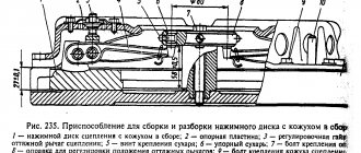
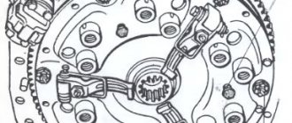
Removing clutch discs from a Gazelle car
We remove the clutch housing (see article - “Removing the clutch housing”).
We use a core to mark the relative position of the casing and flywheel.
1. While holding the flywheel from turning with a screwdriver or a mounting spatula, a wrench or a 12-point socket, unscrew 6 bolts.
2. Remove the drive disk assembly (basket) and the driven disk.
After disassembling, the clutch parts should be washed in kerosene and inspected. Cracks, burrs and deep grooves are not allowed on the surface of the drive discs. If present, replace the flywheel and basket assembly. We replace the driven disk with linings worn to the rivets, warped, cracked, oiled and burnt. The protrusion of the ends of the diaphragm spring petals is controlled using a spacer.
| rice. 3 |
When moving the ends of the petals 8.5 mm down, the pressure plate offset must be at least 1.3 mm, otherwise we replace the drive disk (basket) assembly.
Any cracks or breaks are not allowed on the crankcase. During assembly, we coat the rubbing surfaces of the fork, coupling, pushers and shaft splines with CV joint-4 lubricant.
Install the disks in the following sequence
1. Insert the centering mandrel into the engine flywheel bearing.
2. We put the driven disk on it.
3. On one side the disc hub protrudes less than on the other. This side should be facing the flywheel.
4. Place the basket on the flywheel and secure it with 6 bolts (the holes match only in one position). After tightening the bolts, remove the mandrel.
Dismantling the clutch of a car with an engine model ZMZ-402
We carry out the work in an inspection ditch.
We remove the gearbox.
Dry and wet clutch types
In addition, the clutch can be wet or dry. In the dry type of clutch, the discs operate under dry friction conditions. A wet clutch involves operating the discs in liquid. The most common type in modern vehicles is the dry single-plate clutch.
The wet type of clutch (operating in an oil bath) is now used mainly on motorcycles with a transverse engine. Since motorcycle power units have a common oil sump for both the engine and the gearbox. The clutch parts in them are combined with the motor transmission and engine starting system, and they are lubricated with common engine oil. On cars, oil-bath clutches have almost become obsolete.
Clutch mechanisms in the “young years” of world mechanical engineering
The invention of the clutch mechanism is attributed to Karl Benz. It is impossible to reliably establish whether this is true or not: several companies were simultaneously engaged in the production and improvement of the first cars in the 19th century, and all of them followed their development, as they say, “neck and neck.” The oldest type of clutch, widespread on most cars of the late 19th and early 20th centuries, was the conical type clutch. Its friction surfaces had a conical shape. This clutch transmitted more torque, with the same dimensions, compared to the current single-disc clutch, and was extremely simple in design and maintenance.
The comfortable Mercedes Benz HP-50 is a car with a conical friction clutch.
However, the heavy conical disk of this type of clutch had high inertia, and when changing gears after depressing the pedal, it still continued to rotate at idle, which made engaging the gear a difficult operation. To brake the clutch disc, a special unit was used - a clutch brake, but its use was only half of the solution to the problem, as was the replacement of one cone with two less massive ones. As a result, already in the 1920s, such a heavy and cumbersome (and who requires significant muscular effort to use) design such as a conical clutch was completely abandoned. There was also a reverse cone clutch that worked to release.
However, the very principle of this mechanism has found a new embodiment in the design of modern gearboxes with synchronizers. Transmission synchronizers are essentially small conical clutches that operate by rubbing bronze (or other high-friction metal) against steel.